EP1340909A2 - Zündenstufe - Google Patents
Zündenstufe Download PDFInfo
- Publication number
- EP1340909A2 EP1340909A2 EP03002052A EP03002052A EP1340909A2 EP 1340909 A2 EP1340909 A2 EP 1340909A2 EP 03002052 A EP03002052 A EP 03002052A EP 03002052 A EP03002052 A EP 03002052A EP 1340909 A2 EP1340909 A2 EP 1340909A2
- Authority
- EP
- European Patent Office
- Prior art keywords
- output stage
- ignition
- control unit
- ignition output
- coupling
- Prior art date
- Legal status (The legal status is an assumption and is not a legal conclusion. Google has not performed a legal analysis and makes no representation as to the accuracy of the status listed.)
- Granted
Links
Images

Classifications
-
- F—MECHANICAL ENGINEERING; LIGHTING; HEATING; WEAPONS; BLASTING
- F02—COMBUSTION ENGINES; HOT-GAS OR COMBUSTION-PRODUCT ENGINE PLANTS
- F02P—IGNITION, OTHER THAN COMPRESSION IGNITION, FOR INTERNAL-COMBUSTION ENGINES; TESTING OF IGNITION TIMING IN COMPRESSION-IGNITION ENGINES
- F02P3/00—Other installations
- F02P3/02—Other installations having inductive energy storage, e.g. arrangements of induction coils
- F02P3/04—Layout of circuits
- F02P3/055—Layout of circuits with protective means to prevent damage to the circuit, e.g. semiconductor devices or the ignition coil
- F02P3/0552—Opening or closing the primary coil circuit with semiconductor devices
Definitions
- the present invention relates to an ignition output stage, which is characterized by an engine control unit can be controlled reliably and safely.
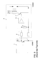
- FIG. 3 shows an example of a control of an ignition module with an ignition output stage represented by an engine control unit according to the prior art.
- coupling means do not necessarily have to be galvanically decoupled between the Bring control unit and the ignition output stage, but for floating coupling between the control unit and the ignition output stage can also be, for example Differential amplifier can be used, which is connected to the control unit connected input resistance falling voltage and recorded in the corresponding Control voltage for the igniter of the ignition output stage.
- FIG. 1 and FIG. 2 show those components which are the same as those in FIG. 3 Components shown correspond to the same reference numerals, so that on a repeated description of these components is omitted and instead the the above description can be referred to Figure 3.
- the following is therefore predominant to the differences according to the invention between those shown in FIG. 1 and FIG. 2 Embodiments and the known ignition output stage shown in Figure 3.
- the ignition module 3 with the ignition output stage is not directly via the wiring harness 2 connected to the engine control unit 1, but the coupling between the Ignition output stage and the wiring harness 2 or the engine control unit 1 takes place via Coupling means 4, which are designed such that they provide a potential-free coupling between the engine control unit 1 and the ignition output stage or the ignition module 3 enable.
- this floating coupling takes place through the use an optocoupler, which is connected on the input side via the cable harness 2 to the Engine control unit 1 or the ground connection VGND1 (body ground) of the Engine control unit 1 is connected.
- an input resistor used in combination with a differential amplifier.
- the Input resistance is with the engine control unit 1 or the corresponding one Earth connection VGND1 (body earth) connected.
- the differential amplifier is with its two input terminals to the two ends of this input resistor connected and thus detects the voltage drop across this input resistance, that is, the control voltage of the engine control unit 1 for the ignition output stage.
- the differential amplifier is shown on the one hand with the Resistor 5 and the control circuit 6 with Standstillabsc Francisco functionality and on the other hand with the igniter 7 and Earth connection VGND2 (engine earth) of the ignition module 3 connected.
- the design of the coupling means 4 for accomplishing a potential-free Coupling between the engine control unit 1 and the ignition module 3 or the one therein contained ignition output stage is of course not on the in Figure 1 and Figure 2 illustrated specific embodiments limited, but it can fundamentally all circuit means or components familiar to the person skilled in the art are used, which is a potential-free coupling between the ignition module 3 or the ignition output stage and enable the engine control unit 1, so that there are potential shifts on the ignition module 3 or a mass offset between the engine control unit 1 and the ignition module 3 is not adversely affect the reliability of the ignition system.
Landscapes
- Engineering & Computer Science (AREA)
- Chemical & Material Sciences (AREA)
- Combustion & Propulsion (AREA)
- Mechanical Engineering (AREA)
- General Engineering & Computer Science (AREA)
- Ignition Installations For Internal Combustion Engines (AREA)
- Combustion Methods Of Internal-Combustion Engines (AREA)
Abstract
Description
- 1
- Motorsteuergerät
- 2
- Kabelbaum
- 3
- Zündmodul
- 4
- potenzialfreie Kopplungsmittel
- 5
- Widerstand
- 6
- Ansteuer- bzw. Regelschaltung
- 7
- Zünder
- 8
- Übertrager
- Vcc1, Vcc2
- Versorgungsspannungsanschluss
- VGND1, VGND2
- Masseanschluss
Claims (7)
- Zündendstufe, mit einem Zünder (7) zur Erzeugung einer Zündspannung für einen Verbrennungsmotor, und mit Kopplungsmitteln (4) zur Kopplung der Zündendstufe mit einem Steuergerät (1) zur Steuerung des Zünders (7),
dadurch gekennzeichnet, dass die Kopplungsmittel (4) derart ausgestaltet sind, dass sie eine potenzialfreie Kopplung zwischen dem Steuergerät (1) und der Zündendstufe (3) ermöglichen. - Zündendstufe nach Anspruch 1,
dadurch gekennzeichnet, dass die Kopplungsmittel (4) ein Kopplungselement zur potenzialfreien Kopplung zwischen dem Steuergerät (1) und der Zündendstufe (3) umfassen, welches ausgangsseitig mit der Zündendstufe (3) gekoppelt und eingangsseitig mit dem Steuergerät (1) zu verbinden ist. - Zündendstufe nach Anspruch 2,
dadurch gekennzeichnet, dass das Kopplungselement ausgangsseitig mit dem Zünder (7) und einem Masseanschluss (VGND2) der Zündendstufe (3) gekoppelt ist. - Zündendstufe nach Anspruch 3,
dadurch gekennzeichnet, dass der Zünder (7) mit einem Übertrager (8) zur Bereitstellung der Zündspannung für den Verbrennungsmotor verbunden ist, wobei eine Primärwicklung des Übertragers (8) mit dem Zünder (7) zwischen einen Versorgungsspannungsanschluss (Vcc2) und den Masseanschluss (VGND2) geschaltet ist, wobei eine die Zündspannung für den Verbrennungsmotor bereitstellende Sekundärwicklung des Übertragers (8) und das Kopplungselement ebenfalls an den Masseanschluss (VGND2) angeschlossen sind. - Zündendstufe nach einem der vorhergehenden Ansprüche,
dadurch gekennzeichnet, dass die Kopplungsmittel (4) zur potenzialfreien Kopplung zwischen dem Steuergerät (1) und der Zündendstufe (3) einen Optokoppler umfassen, welcher ausgangsseitig mit der Zündendstufe (3) gekoppelt und eingangsseitig an das Steuergerät (1) anzuschließen ist. - Zündendstufe nach einem der Ansprüche 1 - 4,
dadurch gekennzeichnet, dass die Kopplungsmittel (4) zur potenzialfreien Kopplung zwischen dem Steuergerät (1) und der Zündendstufe (3) einen Differenzverstärker umfassen, welcher ausgangsseitig mit der Zündendstufe (3) gekoppelt und eingangsseitig an das Steuergerät (1) anzuschließen ist. - Zündendstufe nach Anspruch 6,
dadurch gekennzeichnet, dass der Differenzverstärker die an einem mit dem Steuergerät (1) zu verbindenden Widerstand abfallende Spannung eingangsseitig erfasst.
Applications Claiming Priority (2)
| Application Number | Priority Date | Filing Date | Title |
|---|---|---|---|
| DE10208697 | 2002-02-28 | ||
| DE10208697A DE10208697A1 (de) | 2002-02-28 | 2002-02-28 | Zündendstufe |
Publications (3)
| Publication Number | Publication Date |
|---|---|
| EP1340909A2 true EP1340909A2 (de) | 2003-09-03 |
| EP1340909A3 EP1340909A3 (de) | 2005-09-14 |
| EP1340909B1 EP1340909B1 (de) | 2008-05-28 |
Family
ID=27675114
Family Applications (1)
| Application Number | Title | Priority Date | Filing Date |
|---|---|---|---|
| EP03002052A Expired - Lifetime EP1340909B1 (de) | 2002-02-28 | 2003-01-29 | Zündendstufe |
Country Status (3)
| Country | Link |
|---|---|
| EP (1) | EP1340909B1 (de) |
| AT (1) | ATE397160T1 (de) |
| DE (2) | DE10208697A1 (de) |
Family Cites Families (9)
| Publication number | Priority date | Publication date | Assignee | Title |
|---|---|---|---|---|
| GB1257794A (de) * | 1968-06-28 | 1971-12-22 | ||
| FR2378187A1 (fr) * | 1977-01-21 | 1978-08-18 | Renault | Circuit electronique de prelevement et de mise en forme d'un signal rupteur |
| DE3008066A1 (de) * | 1980-03-03 | 1981-09-17 | Robert Bosch Gmbh, 7000 Stuttgart | Schaltungsanordnung zur zuendung von brennkraftmaschinen |
| US4446841A (en) * | 1982-01-20 | 1984-05-08 | The Bendix Corporation | Photoelectric isolation circuit for an internal combustion engine ignition system |
| DE3900498A1 (de) * | 1989-01-10 | 1990-07-19 | Hermann Mueller | Elektronische zuendanlage ohne zuendverteiler fuer kfz |
| DE4009033A1 (de) * | 1990-03-21 | 1991-09-26 | Bosch Gmbh Robert | Vorrichtung zur unterdrueckung einzelner zuendvorgaenge in einer zuendanlage |
| JPH0454278A (ja) * | 1990-06-22 | 1992-02-21 | Mitsubishi Electric Corp | 内燃機関用点火装置 |
| SE505874C2 (sv) * | 1996-01-23 | 1997-10-20 | Mecel Ab | Mätkrets för detektering av jonisering i förbränningsrummet i en förbränningsmotor |
| US5910737A (en) * | 1997-06-30 | 1999-06-08 | Delco Electronics Corporation | Input buffer circuit with differential input thresholds operable with high common mode input voltages |
-
2002
- 2002-02-28 DE DE10208697A patent/DE10208697A1/de not_active Ceased
-
2003
- 2003-01-29 EP EP03002052A patent/EP1340909B1/de not_active Expired - Lifetime
- 2003-01-29 DE DE50309903T patent/DE50309903D1/de not_active Expired - Lifetime
- 2003-01-29 AT AT03002052T patent/ATE397160T1/de not_active IP Right Cessation
Also Published As
| Publication number | Publication date |
|---|---|
| EP1340909B1 (de) | 2008-05-28 |
| DE10208697A1 (de) | 2003-09-11 |
| ATE397160T1 (de) | 2008-06-15 |
| DE50309903D1 (de) | 2008-07-10 |
| EP1340909A3 (de) | 2005-09-14 |
Similar Documents
| Publication | Publication Date | Title |
|---|---|---|
| DE69517894T2 (de) | Zündgerät für eine innere Brennkraftmaschine | |
| EP1526986B1 (de) | Airbagsteuergerät für ein fahrzeug | |
| DE10235788B4 (de) | Elektrisches Verbindungssystem für ein Kraftfahrzeug | |
| DE19805926A1 (de) | Vorrichtung und Verfahren zum gesteuerten Parallelbetrieb von Gleichspannungswandlern | |
| DE102019007956A1 (de) | Elektronisches Spannungsversorgungssystem | |
| EP0783994B1 (de) | Steuerungssystem für einen Generator eines Kraftfahrzeuges | |
| EP0314681B1 (de) | Endstufe in brückenschaltung | |
| EP1720737B1 (de) | Vorrichtung zur bestromung wenigstens einer zündendstufe mittels eines zündstroms aus einer energiereserve | |
| EP4057475A1 (de) | Energieversorgung eines elektrogeräts mittels eines akkupacks und laden eines akkupacks anhand eines adapters | |
| WO2016001289A1 (de) | Aktuator mit positionssensor | |
| DE102010026768A1 (de) | Kraftfahrzeugsicherheitssystem für eine elektrische Kraftfahrzeugantriebsvorrichtung | |
| EP1340909B1 (de) | Zündendstufe | |
| DE10232941B4 (de) | KFZ-Bordnetz mit einer Sensor-Schutzschaltung | |
| DE102013214953A1 (de) | Anordnung zum Anschluss einer Komponente an ein Master- Steuergerät eines Kraftfahrzeugs | |
| DE102020112985A1 (de) | IO-Link-Adapter | |
| DE102017203147A1 (de) | Vorrichtung und Verfahren zum Betreiben eines Kraftfahrzeugs, Kraftfahrzeug | |
| DE102018217574A1 (de) | Fahrzeugbordnetz mit erstem Bordnetzzweig, zweiten Bordnetzzweig und Gleichspannungswandler | |
| DE102008050289A1 (de) | Parallelschaltgetriebe | |
| DE102013002080A1 (de) | Elektrische Konvertierungseinrichtung für ein Elektro- oder Hybridfahrzeug | |
| DE102018212767A1 (de) | Kraftfahrzeugbordnetz mit einer Isolationsüberwachung zur Versorgung einer Umfeldsensorik | |
| WO2002097943A2 (de) | Verpolschutz für energiequellen | |
| EP2106008B1 (de) | Sensorsteuergerät für ein Fahrzeug und Verfahren zum Betrieb eines solchen Sensorsteuergeräts | |
| EP1392970A1 (de) | Zündvorrichtung, steuergerät und zündanlage für eine brennkraftmaschine | |
| DE10254225B4 (de) | Zündvorrichtung für einen Verbrennungsmotor | |
| DE102009039579B4 (de) | Kraftfahrzeug mit einer Gleichspannungswandler-Anordnung |
Legal Events
| Date | Code | Title | Description |
|---|---|---|---|
| PUAI | Public reference made under article 153(3) epc to a published international application that has entered the european phase |
Free format text: ORIGINAL CODE: 0009012 |
|
| AK | Designated contracting states |
Kind code of ref document: A2 Designated state(s): AT BE BG CH CY CZ DE DK EE ES FI FR GB GR HU IE IT LI LU MC NL PT SE SI SK TR |
|
| AX | Request for extension of the european patent |
Extension state: AL LT LV MK RO |
|
| PUAL | Search report despatched |
Free format text: ORIGINAL CODE: 0009013 |
|
| AK | Designated contracting states |
Kind code of ref document: A3 Designated state(s): AT BE BG CH CY CZ DE DK EE ES FI FR GB GR HU IE IT LI LU MC NL PT SE SI SK TR |
|
| AX | Request for extension of the european patent |
Extension state: AL LT LV MK RO |
|
| 17P | Request for examination filed |
Effective date: 20060314 |
|
| AKX | Designation fees paid |
Designated state(s): AT BE BG CH CY CZ DE DK EE ES FI FR GB GR HU IE IT LI LU MC NL PT SE SI SK TR |
|
| 17Q | First examination report despatched |
Effective date: 20060620 |
|
| GRAP | Despatch of communication of intention to grant a patent |
Free format text: ORIGINAL CODE: EPIDOSNIGR1 |
|
| GRAS | Grant fee paid |
Free format text: ORIGINAL CODE: EPIDOSNIGR3 |
|
| GRAA | (expected) grant |
Free format text: ORIGINAL CODE: 0009210 |
|
| AK | Designated contracting states |
Kind code of ref document: B1 Designated state(s): AT BE BG CH CY CZ DE DK EE ES FI FR GB GR HU IE IT LI LU MC NL PT SE SI SK TR |
|
| REG | Reference to a national code |
Ref country code: GB Ref legal event code: FG4D Free format text: NOT ENGLISH |
|
| REG | Reference to a national code |
Ref country code: CH Ref legal event code: EP |
|
| REF | Corresponds to: |
Ref document number: 50309903 Country of ref document: DE Date of ref document: 20080710 Kind code of ref document: P |
|
| REG | Reference to a national code |
Ref country code: IE Ref legal event code: FG4D Free format text: LANGUAGE OF EP DOCUMENT: GERMAN |
|
| PG25 | Lapsed in a contracting state [announced via postgrant information from national office to epo] |
Ref country code: SI Free format text: LAPSE BECAUSE OF FAILURE TO SUBMIT A TRANSLATION OF THE DESCRIPTION OR TO PAY THE FEE WITHIN THE PRESCRIBED TIME-LIMIT Effective date: 20080528 |
|
| PG25 | Lapsed in a contracting state [announced via postgrant information from national office to epo] |
Ref country code: FI Free format text: LAPSE BECAUSE OF FAILURE TO SUBMIT A TRANSLATION OF THE DESCRIPTION OR TO PAY THE FEE WITHIN THE PRESCRIBED TIME-LIMIT Effective date: 20080528 Ref country code: ES Free format text: LAPSE BECAUSE OF FAILURE TO SUBMIT A TRANSLATION OF THE DESCRIPTION OR TO PAY THE FEE WITHIN THE PRESCRIBED TIME-LIMIT Effective date: 20080908 |
|
| PG25 | Lapsed in a contracting state [announced via postgrant information from national office to epo] |
Ref country code: NL Free format text: LAPSE BECAUSE OF FAILURE TO SUBMIT A TRANSLATION OF THE DESCRIPTION OR TO PAY THE FEE WITHIN THE PRESCRIBED TIME-LIMIT Effective date: 20080528 |
|
| NLV1 | Nl: lapsed or annulled due to failure to fulfill the requirements of art. 29p and 29m of the patents act | ||
| REG | Reference to a national code |
Ref country code: IE Ref legal event code: FD4D |
|
| PG25 | Lapsed in a contracting state [announced via postgrant information from national office to epo] |
Ref country code: IE Free format text: LAPSE BECAUSE OF FAILURE TO SUBMIT A TRANSLATION OF THE DESCRIPTION OR TO PAY THE FEE WITHIN THE PRESCRIBED TIME-LIMIT Effective date: 20080528 Ref country code: SE Free format text: LAPSE BECAUSE OF FAILURE TO SUBMIT A TRANSLATION OF THE DESCRIPTION OR TO PAY THE FEE WITHIN THE PRESCRIBED TIME-LIMIT Effective date: 20080828 Ref country code: PT Free format text: LAPSE BECAUSE OF FAILURE TO SUBMIT A TRANSLATION OF THE DESCRIPTION OR TO PAY THE FEE WITHIN THE PRESCRIBED TIME-LIMIT Effective date: 20081028 Ref country code: DK Free format text: LAPSE BECAUSE OF FAILURE TO SUBMIT A TRANSLATION OF THE DESCRIPTION OR TO PAY THE FEE WITHIN THE PRESCRIBED TIME-LIMIT Effective date: 20080528 |
|
| PG25 | Lapsed in a contracting state [announced via postgrant information from national office to epo] |
Ref country code: SK Free format text: LAPSE BECAUSE OF FAILURE TO SUBMIT A TRANSLATION OF THE DESCRIPTION OR TO PAY THE FEE WITHIN THE PRESCRIBED TIME-LIMIT Effective date: 20080528 |
|
| PLBE | No opposition filed within time limit |
Free format text: ORIGINAL CODE: 0009261 |
|
| STAA | Information on the status of an ep patent application or granted ep patent |
Free format text: STATUS: NO OPPOSITION FILED WITHIN TIME LIMIT |
|
| PG25 | Lapsed in a contracting state [announced via postgrant information from national office to epo] |
Ref country code: BG Free format text: LAPSE BECAUSE OF FAILURE TO SUBMIT A TRANSLATION OF THE DESCRIPTION OR TO PAY THE FEE WITHIN THE PRESCRIBED TIME-LIMIT Effective date: 20080828 Ref country code: EE Free format text: LAPSE BECAUSE OF FAILURE TO SUBMIT A TRANSLATION OF THE DESCRIPTION OR TO PAY THE FEE WITHIN THE PRESCRIBED TIME-LIMIT Effective date: 20080528 |
|
| 26N | No opposition filed |
Effective date: 20090303 |
|
| PG25 | Lapsed in a contracting state [announced via postgrant information from national office to epo] |
Ref country code: MC Free format text: LAPSE BECAUSE OF NON-PAYMENT OF DUE FEES Effective date: 20090131 Ref country code: IT Free format text: LAPSE BECAUSE OF FAILURE TO SUBMIT A TRANSLATION OF THE DESCRIPTION OR TO PAY THE FEE WITHIN THE PRESCRIBED TIME-LIMIT Effective date: 20080528 |
|
| REG | Reference to a national code |
Ref country code: CH Ref legal event code: PL |
|
| PG25 | Lapsed in a contracting state [announced via postgrant information from national office to epo] |
Ref country code: LI Free format text: LAPSE BECAUSE OF NON-PAYMENT OF DUE FEES Effective date: 20090131 Ref country code: CH Free format text: LAPSE BECAUSE OF NON-PAYMENT OF DUE FEES Effective date: 20090131 |
|
| PG25 | Lapsed in a contracting state [announced via postgrant information from national office to epo] |
Ref country code: BE Free format text: LAPSE BECAUSE OF NON-PAYMENT OF DUE FEES Effective date: 20090131 |
|
| PG25 | Lapsed in a contracting state [announced via postgrant information from national office to epo] |
Ref country code: AT Free format text: LAPSE BECAUSE OF NON-PAYMENT OF DUE FEES Effective date: 20090129 |
|
| PG25 | Lapsed in a contracting state [announced via postgrant information from national office to epo] |
Ref country code: GR Free format text: LAPSE BECAUSE OF FAILURE TO SUBMIT A TRANSLATION OF THE DESCRIPTION OR TO PAY THE FEE WITHIN THE PRESCRIBED TIME-LIMIT Effective date: 20080829 |
|
| PG25 | Lapsed in a contracting state [announced via postgrant information from national office to epo] |
Ref country code: LU Free format text: LAPSE BECAUSE OF NON-PAYMENT OF DUE FEES Effective date: 20090129 |
|
| PG25 | Lapsed in a contracting state [announced via postgrant information from national office to epo] |
Ref country code: HU Free format text: LAPSE BECAUSE OF FAILURE TO SUBMIT A TRANSLATION OF THE DESCRIPTION OR TO PAY THE FEE WITHIN THE PRESCRIBED TIME-LIMIT Effective date: 20081129 |
|
| PG25 | Lapsed in a contracting state [announced via postgrant information from national office to epo] |
Ref country code: TR Free format text: LAPSE BECAUSE OF FAILURE TO SUBMIT A TRANSLATION OF THE DESCRIPTION OR TO PAY THE FEE WITHIN THE PRESCRIBED TIME-LIMIT Effective date: 20080528 |
|
| PG25 | Lapsed in a contracting state [announced via postgrant information from national office to epo] |
Ref country code: CY Free format text: LAPSE BECAUSE OF FAILURE TO SUBMIT A TRANSLATION OF THE DESCRIPTION OR TO PAY THE FEE WITHIN THE PRESCRIBED TIME-LIMIT Effective date: 20080528 |
|
| REG | Reference to a national code |
Ref country code: FR Ref legal event code: PLFP Year of fee payment: 14 |
|
| REG | Reference to a national code |
Ref country code: FR Ref legal event code: PLFP Year of fee payment: 15 |
|
| REG | Reference to a national code |
Ref country code: FR Ref legal event code: PLFP Year of fee payment: 16 |
|
| PGFP | Annual fee paid to national office [announced via postgrant information from national office to epo] |
Ref country code: DE Payment date: 20190131 Year of fee payment: 17 Ref country code: CZ Payment date: 20190125 Year of fee payment: 17 Ref country code: GB Payment date: 20190130 Year of fee payment: 17 Ref country code: FR Payment date: 20190130 Year of fee payment: 17 |
|
| REG | Reference to a national code |
Ref country code: DE Ref legal event code: R082 Ref document number: 50309903 Country of ref document: DE |
|
| REG | Reference to a national code |
Ref country code: DE Ref legal event code: R119 Ref document number: 50309903 Country of ref document: DE |
|
| GBPC | Gb: european patent ceased through non-payment of renewal fee |
Effective date: 20200129 |
|
| PG25 | Lapsed in a contracting state [announced via postgrant information from national office to epo] |
Ref country code: FR Free format text: LAPSE BECAUSE OF NON-PAYMENT OF DUE FEES Effective date: 20200131 Ref country code: DE Free format text: LAPSE BECAUSE OF NON-PAYMENT OF DUE FEES Effective date: 20200801 Ref country code: GB Free format text: LAPSE BECAUSE OF NON-PAYMENT OF DUE FEES Effective date: 20200129 Ref country code: CZ Free format text: LAPSE BECAUSE OF NON-PAYMENT OF DUE FEES Effective date: 20200129 |