EP1339991B1 - Schlauchfassung für betätigungszüge - Google Patents
Schlauchfassung für betätigungszüge Download PDFInfo
- Publication number
- EP1339991B1 EP1339991B1 EP01996691A EP01996691A EP1339991B1 EP 1339991 B1 EP1339991 B1 EP 1339991B1 EP 01996691 A EP01996691 A EP 01996691A EP 01996691 A EP01996691 A EP 01996691A EP 1339991 B1 EP1339991 B1 EP 1339991B1
- Authority
- EP
- European Patent Office
- Prior art keywords
- hose
- hose mount
- mount according
- damping
- fastening element
- Prior art date
- Legal status (The legal status is an assumption and is not a legal conclusion. Google has not performed a legal analysis and makes no representation as to the accuracy of the status listed.)
- Expired - Lifetime
Links
- 238000013016 damping Methods 0.000 claims description 46
- 230000005540 biological transmission Effects 0.000 description 2
- 230000000903 blocking effect Effects 0.000 description 2
- 238000004519 manufacturing process Methods 0.000 description 2
- 230000000694 effects Effects 0.000 description 1
- 238000003780 insertion Methods 0.000 description 1
- 230000037431 insertion Effects 0.000 description 1
- 238000009434 installation Methods 0.000 description 1
- 238000007789 sealing Methods 0.000 description 1
Images


Classifications
-
- F—MECHANICAL ENGINEERING; LIGHTING; HEATING; WEAPONS; BLASTING
- F16—ENGINEERING ELEMENTS AND UNITS; GENERAL MEASURES FOR PRODUCING AND MAINTAINING EFFECTIVE FUNCTIONING OF MACHINES OR INSTALLATIONS; THERMAL INSULATION IN GENERAL
- F16C—SHAFTS; FLEXIBLE SHAFTS; ELEMENTS OR CRANKSHAFT MECHANISMS; ROTARY BODIES OTHER THAN GEARING ELEMENTS; BEARINGS
- F16C1/00—Flexible shafts; Mechanical means for transmitting movement in a flexible sheathing
- F16C1/26—Construction of guiding-sheathings or guiding-tubes
- F16C1/262—End fittings; Attachment thereof to the sheathing or tube
Definitions
- the invention relates to a hose socket for Operating cables according to the preamble of claim 1 ..
- Such hose sockets come, for example, with switching and Selector cables as a transmission element between gear lever and Gearbox of a motor vehicle for use.
- the hose sockets have one on the outer hose of the actuating cable pressed fastening element and a connection socket, which are interconnectable.
- the connection version is in turn connectable with an articulated tube.
- the articulated tube serves to compensate for angular movements between the transmission side and Connection element and is in a through the Fastening element and the connection socket formed recess with a funnel-shaped extension, which makes it flexible in the Hose socket is stored.
- the invention is based on the object Hose socket for actuation cables of the type mentioned at the beginning indicate what a noise level in the occurring Avoids operating cases.
- this is the Fastening element associated damping element between the outer hose of the actuating cable and the fastener and / or the damping element facing the cable sheath end piece between the connection element and the cable sheath end piece arranged.
- a noise development through the hose socket is further minimized because the damping elements Noise between the fastener and the Actuating cable or between the cable sheath end piece and the Suppress the actuation cable.
- the holding elements are the holding elements as parallel to the longitudinal axis of the Pins designed to extend the hose socket.
- the holding elements and the recesses are advantageously around arranged the longitudinal axis of the hose socket. This is ensures that the damping elements move freely perpendicular to the longitudinal axis of the hose socket over the entire radial area of the longitudinal axis in the area of the damping elements is minimized.
- the freedom of movement is further reduced by the Holding elements and the recesses non-positively and / or positively are interconnectable.
- the advantageous measure also aims in the same direction, that the damping elements are supported on the collar. For is practically all occurring operating cases ensures that the damping elements lie against the collar and the movements occurring within the hose socket intercept by their elasticity. A noise development can therefore it does not arise in the first place.
- the damping elements each have two at a radial distance mutually arranged coaxial ring parts on the Crosspieces are connected to each other.
- connection element for example one Articulated tube with which the hose socket is reached and thus a incorrect or improper connection of the connection element with the hose socket cannot occur.
- the Damping elements for the fastener and that Rope cover end piece are formed as identical parts, so that no different damping elements are produced have to.
- the hose socket 1 of an actuating cable is closed recognize which, for example, by pressing on the outer Hose (26) of the actuating cable can be applied.
- a fastening element 2 can be pushed onto the hose socket 1.
- the fastening element 2 is a cable sleeve end piece 3 connectable, for example. Via a snap connection by locking tabs 4 in engage corresponding window 5 of the fastener 2.
- the cable sheath end piece 3 can be pushed onto an articulated tube 6, which at its end facing the fastening element 1 Has funnel-shaped expansion 7.
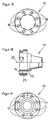
- the damping element 12 is in Figures 8 and 9, the Damping element 13 shown in Figures 10 and 11.
Landscapes
- Engineering & Computer Science (AREA)
- General Engineering & Computer Science (AREA)
- Health & Medical Sciences (AREA)
- Oral & Maxillofacial Surgery (AREA)
- Mechanical Engineering (AREA)
- Flexible Shafts (AREA)
Description
- Figur 1
- eine mögliche Ausführungsform einer erfindungsgemäßen Schlauchfassung, teilweise im Längsschnitt,
- Figur 2
- die Darstellung der Schlauchfassung gemäß Figur 1 in der Schnittebene A-A,
- Figur 3
- eine Schnittdarstellung eines Befestigungselements der Schlauchfassung gemäß Figur 1,
- Figur 4
- eine Draufsicht auf das Befestigungselement gemäß Figur 3,
- Figur 5
- einen Längsschnitt eines Seilhüllenendstückes der Schlauchfassung gemäß Figur 1,
- Figur 6
- eine Draufsicht auf das Seilhüllenendstück gemäß Figur 5,
- Figur 7
- eine Ansicht des Befestigungselementes gemäß Figur 1,
- Figur 8
- ein in dem Gehäusedeckel gehaltenes Dämpfungselement,
- Figur 9
- das Dämpfungselement gemäß Figur 8 in einer Draufsicht,
- Figur 10
- ein dem Seilhüllenendstück zugeordnetes Dämpfungselement in einer Querschnittsdarstellung und
- Figur 11
- das Dämpfungselement gemäß Figur 10 in einer Draufsicht.
- 1 -
- Schlauchfassung
- 2 -
- Befestigungselement
- 3 -
- Seilhüllenendstück
- 4 -
- Rastnase
- 5 -
- Fenster
- 6 -
- Gelenkrohr
- 7 -
- Aufweitung
- 9 -
- Aussparung
- 10 -
- Flansch
- 11 -
- Tülle
- 12 -
- Dämpfungselement
- 13 -
- Dämpfungselement
- 14 -
- Stift, Haltelement
- 15 -
- Stift
- 16 -
- Ausnehmung
- 17 -
- Ausnehmung
- 18 -
- Verbindungssteg
- 19 -
- Verbindungssteg
- 20 -
- Ringteil
- 21 -
- Ringteil
- 22 -
- Ringteil
- 23 -
- Ringteil
- 24 -
- radialer Bund
- 25 -
- Längsachse
- 26 -
- Schlauch
Claims (14)
- Schlauchfassung (1) für Betätigungszüge mit einem Seilhüllenendstück (3) und mit einem damit verbindbaren Befestigungselement (2), wobei das Befestigungselement (2) mit einem äußeren Schlauch (26) des Betätigungszuges verbindbar ist und innerhalb der Schlauchfassung (1) sowohl dem Befestigungselement (2) als auch dem Seilhüllenendstück (3) jeweils ein Dämpfungselement (12, 13) zugeordnet ist, dadurch gekennzeichnet, dass an dem Befestigungselement (2) und an dem Seilhüllenendstück (3) mehrere Halteelemente (14, 15) angeordnet sind, die in zugeordnete Ausnehmungen (16, 17) der Dämpfungselemente (12, 13) eingreifen.
- Schlauchfassung nach Anspruch 1, dadurch gekennzeichnet, dass das Dämpfungselement (12) zwischen dem äußeren Schlauch (26) des Betätigungszuges und dem Befestigungselement (2) und/oder das Dämpfungselement (13) zwischen einem Anschlusselement (6) und dem Seilhüllenendstück (3) angeordnet ist.
- Schlauchfassung nach Anspruch 1 oder 2, dadurch gekennzeichnet, dass die Dämpfungselemente (12, 13) als Gummidichtungen ausgebildet sind.
- Schlauchfassung nach einem der vorhergehenden Ansprüche, dadurch gekennzeichnet, dass die Haltelemente (14, 15) als sich parallel zur Längsachse (25) der Schlauchfassung (1) erstreckende Stifte (14, 15) ausgebildet sind.
- Schlauchfassung nach einem der vorhergehenden Ansprüche, dadurch gekennzeichnet, dass die Halteelemente (14, 15) und die Ausnehmungen (16, 17) um die Längsachse (25) der Schlauchfassung (1) angeordnet sind.
- Schlauchfassung einem der vorhergehenden Ansprüche, dadurch gekennzeichnet, dass die Halteelemente (14, 15) und die Ausnehmungen (16, 17) kraft- und/oder formschlüssig miteinander verbindbar sind.
- Schlauchfassung nach einem der vorhergehenden Ansprüche, dadurch gekennzeichnet, dass sie einen umlaufenden Bund (24) zur Erzeugung eines Abstandes zwischen den Dämpfungselementen (12, 13) aufweist.
- Schlauchfassung nach einem der vorhergehenden Ansprüche, dadurch gekennzeichnet, dass sich an dem Bund (24) die Dämpfungselemente (12, 13) abstützen.
- Schlauchfassung nach einem der vorhergehenden Ansprüche, dadurch gekennzeichnet, dass die Dämpfungselemente (12, 13) jeweils zwei in radialem Abstand zueinander angeordnete koaxiale Ringteile (20, 21 bzw. 22, 23) aufweisen, die über Verbindungsstege (18, 19) miteinander verbunden sind.
- Schlauchfassung nach einem der vorhergehenden Ansprüche, dadurch gekennzeichnet, dass das Seilhüllenendstück (3) und das Befestigungselement (2) lösbar miteinander verbindbar sind.
- Schlauchfassung nach einem der vorhergehenden Ansprüche, dadurch gekennzeichnet, dass das Seilhüllenendstück (3) und das Befestigungselement (2) mittels einer Rastverbindung kraft- und/oder formschlüssig miteinander verbindbar sind.
- Schlauchfassung nach einer der vorhergehenden Ansprüche, dadurch gekennzeichnet, dass eine Aussparung (9) für eine trichterförmige Aufweitung (7) des Anschlußelementes (6) vorgesehen ist.
- Schlauchfassung nach Anspruch 12, dadurch gekennzeichnet, dass die Aufweitung (7) einen von einer geräuschdämmenden Tülle (11) umgebenen äußeren Rand bzw. Flansch (10) aufweist.
- Schlauchfassung nach einer der vorhergehenden Ansprüche, dadurch gekennzeichnet, dass die Dämpfungselemente (12, 13) als Gleichteile ausgebildet sind.
Applications Claiming Priority (3)
| Application Number | Priority Date | Filing Date | Title |
|---|---|---|---|
| DE10065836 | 2000-11-20 | ||
| DE10065836 | 2000-11-20 | ||
| PCT/EP2001/013342 WO2002040878A1 (de) | 2000-11-20 | 2001-11-19 | Schlauchfassung für betätigungszüge |
Publications (2)
| Publication Number | Publication Date |
|---|---|
| EP1339991A1 EP1339991A1 (de) | 2003-09-03 |
| EP1339991B1 true EP1339991B1 (de) | 2004-09-22 |
Family
ID=7669499
Family Applications (1)
| Application Number | Title | Priority Date | Filing Date |
|---|---|---|---|
| EP01996691A Expired - Lifetime EP1339991B1 (de) | 2000-11-20 | 2001-11-19 | Schlauchfassung für betätigungszüge |
Country Status (3)
| Country | Link |
|---|---|
| EP (1) | EP1339991B1 (de) |
| DE (1) | DE50103805D1 (de) |
| WO (1) | WO2002040878A1 (de) |
Families Citing this family (1)
| Publication number | Priority date | Publication date | Assignee | Title |
|---|---|---|---|---|
| DE102005020813B4 (de) * | 2005-05-04 | 2011-06-30 | Küster Automotive Control Systems GmbH, 35630 | Vorrichtung zum Befestigen eines Betätigungszuges an einem Halter oder dergleichen |
Family Cites Families (4)
| Publication number | Priority date | Publication date | Assignee | Title |
|---|---|---|---|---|
| EP0627570A1 (de) * | 1993-05-05 | 1994-12-07 | VOFA-WERK XAVIER VORBRÜGGEN GmbH & Co. KG | Anschlussteil für einen Betätigungszug |
| US5448926A (en) * | 1993-11-03 | 1995-09-12 | Teleflex Incorporated | Remote control assembly with vibration dampener |
| IT1285236B1 (it) * | 1996-02-13 | 1998-06-03 | Sila Telecomandi S P A | Gruppo di ritegno di un corpo allungato, particolarmente della guaina di un cavo flessibile rispetto ad una staffa di sopporto |
| IT1304991B1 (it) * | 1998-09-15 | 2001-04-05 | Sila Holding Ind S R L | Cavo di comando flessibile, particolarmente per cambi di autoveicoli. |
-
2001
- 2001-11-19 EP EP01996691A patent/EP1339991B1/de not_active Expired - Lifetime
- 2001-11-19 WO PCT/EP2001/013342 patent/WO2002040878A1/de not_active Ceased
- 2001-11-19 DE DE50103805T patent/DE50103805D1/de not_active Expired - Lifetime
Also Published As
| Publication number | Publication date |
|---|---|
| WO2002040878A1 (de) | 2002-05-23 |
| DE50103805D1 (de) | 2004-10-28 |
| EP1339991A1 (de) | 2003-09-03 |
Similar Documents
| Publication | Publication Date | Title |
|---|---|---|
| EP1250733B1 (de) | Elektrischer steckverbinder | |
| EP0925631B1 (de) | Adaptersystem | |
| DE69315844T2 (de) | Drehbare temperatureinstellvorrichtung | |
| DE19810665C1 (de) | Bowdenzug zur Übertragung von Zugkräften | |
| EP0186840B1 (de) | Lagergehäuse für Kraftfahrzeug-Gangschalthebel mit Rückwärtsgangsperre | |
| DE102005018899A1 (de) | Rastelement | |
| DE9400555U1 (de) | Anschlußteil für einen Betätigungszug | |
| DE3626403A1 (de) | Anschlussarmatur | |
| DE29614558U1 (de) | Betätigungszug für die Betätigung von Einrichtungen insbesondere in Fahrzeugen | |
| WO2000003459A1 (de) | Elektrischer steckverbinder | |
| DE19528953A1 (de) | Befestigungselement für einen Betätigungszug | |
| DE102008000404A1 (de) | Transportsicherung für einen Drehmomentwandler | |
| DE102020214739A1 (de) | Fensterheber mit einer Vorrichtung zum Seillängenausgleich | |
| WO2002040878A1 (de) | Schlauchfassung für betätigungszüge | |
| DE19855051B4 (de) | Drehschalter mit begrenzter Drehung, insbesondere für Kraftfahrzeuge | |
| DE102014204897A1 (de) | Rastvorrichtung sowie Getriebeanordnung mit der Rastvorrichtung | |
| EP2400170A2 (de) | Betätigungseinrichtung | |
| DE102014206713A1 (de) | Übertragungseinrichtung von Wähl- und Schaltbewegungen und damit versehene Schalteinrichtung | |
| DE10161539A1 (de) | Aufnahme mit einer Achse zur Drehbedienung eines Schaltgeräts o. dgl. | |
| WO2001013000A1 (de) | Führungskörper für mechanisch-flexible fernbetätigungen | |
| DE19901950A1 (de) | Bowdenzugeinheit, insbesondere zur Übertragung der Schaltbewegung von einem Schaltbetätigungshebel zu einem Stufenwechselgetriebe in Kraftfahrzeugen | |
| WO2025016889A1 (de) | Umlenkeinrichtung für ein zugseil eines seilfensterhebers | |
| DE29613746U1 (de) | Schlauchfassung zur lösbaren Befestigung eines Außenschlauches eines Betätigungszuges | |
| EP2096329B1 (de) | Synchonisiereinrichtung für Schaltgetriebe | |
| DE19903850A1 (de) | Rastvorrichtung für die Lagefixierung der Dreh- oder Längsbewegung einer Welle |
Legal Events
| Date | Code | Title | Description |
|---|---|---|---|
| PUAI | Public reference made under article 153(3) epc to a published international application that has entered the european phase |
Free format text: ORIGINAL CODE: 0009012 |
|
| 17P | Request for examination filed |
Effective date: 20020704 |
|
| AK | Designated contracting states |
Kind code of ref document: A1 Designated state(s): AT BE CH CY DE DK ES FI FR GB GR IE IT LI LU MC NL PT SE TR |
|
| GRAP | Despatch of communication of intention to grant a patent |
Free format text: ORIGINAL CODE: EPIDOSNIGR1 |
|
| GRAS | Grant fee paid |
Free format text: ORIGINAL CODE: EPIDOSNIGR3 |
|
| GRAA | (expected) grant |
Free format text: ORIGINAL CODE: 0009210 |
|
| AK | Designated contracting states |
Kind code of ref document: B1 Designated state(s): DE ES FR GB IT |
|
| PG25 | Lapsed in a contracting state [announced via postgrant information from national office to epo] |
Ref country code: IT Free format text: LAPSE BECAUSE OF FAILURE TO SUBMIT A TRANSLATION OF THE DESCRIPTION OR TO PAY THE FEE WITHIN THE PRESCRIBED TIME-LIMIT;WARNING: LAPSES OF ITALIAN PATENTS WITH EFFECTIVE DATE BEFORE 2007 MAY HAVE OCCURRED AT ANY TIME BEFORE 2007. THE CORRECT EFFECTIVE DATE MAY BE DIFFERENT FROM THE ONE RECORDED. Effective date: 20040922 Ref country code: GB Free format text: LAPSE BECAUSE OF FAILURE TO SUBMIT A TRANSLATION OF THE DESCRIPTION OR TO PAY THE FEE WITHIN THE PRESCRIBED TIME-LIMIT Effective date: 20040922 Ref country code: FR Free format text: LAPSE BECAUSE OF FAILURE TO SUBMIT A TRANSLATION OF THE DESCRIPTION OR TO PAY THE FEE WITHIN THE PRESCRIBED TIME-LIMIT Effective date: 20040922 |
|
| REG | Reference to a national code |
Ref country code: GB Ref legal event code: FG4D Free format text: NOT ENGLISH |
|
| REG | Reference to a national code |
Ref country code: IE Ref legal event code: FG4D Free format text: GERMAN |
|
| REF | Corresponds to: |
Ref document number: 50103805 Country of ref document: DE Date of ref document: 20041028 Kind code of ref document: P |
|
| PG25 | Lapsed in a contracting state [announced via postgrant information from national office to epo] |
Ref country code: ES Free format text: LAPSE BECAUSE OF FAILURE TO SUBMIT A TRANSLATION OF THE DESCRIPTION OR TO PAY THE FEE WITHIN THE PRESCRIBED TIME-LIMIT Effective date: 20050102 |
|
| GBV | Gb: ep patent (uk) treated as always having been void in accordance with gb section 77(7)/1977 [no translation filed] |
Effective date: 20040922 |
|
| REG | Reference to a national code |
Ref country code: IE Ref legal event code: FD4D |
|
| PLBE | No opposition filed within time limit |
Free format text: ORIGINAL CODE: 0009261 |
|
| STAA | Information on the status of an ep patent application or granted ep patent |
Free format text: STATUS: NO OPPOSITION FILED WITHIN TIME LIMIT |
|
| 26N | No opposition filed |
Effective date: 20050623 |
|
| EN | Fr: translation not filed | ||
| PGFP | Annual fee paid to national office [announced via postgrant information from national office to epo] |
Ref country code: DE Payment date: 20201130 Year of fee payment: 20 |
|
| REG | Reference to a national code |
Ref country code: DE Ref legal event code: R071 Ref document number: 50103805 Country of ref document: DE |