EP1339326B1 - Appareil d'echantillonnage et d'elimination de tissus - Google Patents
Appareil d'echantillonnage et d'elimination de tissus Download PDFInfo
- Publication number
- EP1339326B1 EP1339326B1 EP01990207A EP01990207A EP1339326B1 EP 1339326 B1 EP1339326 B1 EP 1339326B1 EP 01990207 A EP01990207 A EP 01990207A EP 01990207 A EP01990207 A EP 01990207A EP 1339326 B1 EP1339326 B1 EP 1339326B1
- Authority
- EP
- European Patent Office
- Prior art keywords
- tissue
- cutter
- housing
- needle
- gear
- Prior art date
- Legal status (The legal status is an assumption and is not a legal conclusion. Google has not performed a legal analysis and makes no representation as to the accuracy of the status listed.)
- Expired - Lifetime
Links
Images


Classifications
-
- A—HUMAN NECESSITIES
- A61—MEDICAL OR VETERINARY SCIENCE; HYGIENE
- A61B—DIAGNOSIS; SURGERY; IDENTIFICATION
- A61B10/00—Other methods or instruments for diagnosis, e.g. instruments for taking a cell sample, for biopsy, for vaccination diagnosis; Sex determination; Ovulation-period determination; Throat striking implements
- A61B10/02—Instruments for taking cell samples or for biopsy
- A61B10/0233—Pointed or sharp biopsy instruments
- A61B10/0266—Pointed or sharp biopsy instruments means for severing sample
- A61B10/0275—Pointed or sharp biopsy instruments means for severing sample with sample notch, e.g. on the side of inner stylet
-
- A—HUMAN NECESSITIES
- A61—MEDICAL OR VETERINARY SCIENCE; HYGIENE
- A61B—DIAGNOSIS; SURGERY; IDENTIFICATION
- A61B10/00—Other methods or instruments for diagnosis, e.g. instruments for taking a cell sample, for biopsy, for vaccination diagnosis; Sex determination; Ovulation-period determination; Throat striking implements
- A61B10/02—Instruments for taking cell samples or for biopsy
- A61B10/0233—Pointed or sharp biopsy instruments
- A61B10/0283—Pointed or sharp biopsy instruments with vacuum aspiration, e.g. caused by retractable plunger or by connected syringe
-
- A—HUMAN NECESSITIES
- A61—MEDICAL OR VETERINARY SCIENCE; HYGIENE
- A61B—DIAGNOSIS; SURGERY; IDENTIFICATION
- A61B10/00—Other methods or instruments for diagnosis, e.g. instruments for taking a cell sample, for biopsy, for vaccination diagnosis; Sex determination; Ovulation-period determination; Throat striking implements
- A61B10/02—Instruments for taking cell samples or for biopsy
- A61B2010/0208—Biopsy devices with actuators, e.g. with triggered spring mechanisms
-
- A—HUMAN NECESSITIES
- A61—MEDICAL OR VETERINARY SCIENCE; HYGIENE
- A61B—DIAGNOSIS; SURGERY; IDENTIFICATION
- A61B10/00—Other methods or instruments for diagnosis, e.g. instruments for taking a cell sample, for biopsy, for vaccination diagnosis; Sex determination; Ovulation-period determination; Throat striking implements
- A61B10/02—Instruments for taking cell samples or for biopsy
- A61B2010/0225—Instruments for taking cell samples or for biopsy for taking multiple samples
Definitions
- the present invention relates to tissue sample removal and, more particularly, breast tissue biopsy apparatus.
- tissue and biopsy removal apparatus and methods include various types of needle coring and moveable cutter devices. Certain of such devices lack effective cutting ability, the ability to retrieve multiple samples, or versatility in terms of use with a variety of accessories and in a variety of procedures. For example, certain tissue removal devices are limited in terms of their need to be used only with certain types of tables or imaging equipment. Some tables or imaging equipment are expensive or cumbersome. Some tables or imaging equipment are adapted to fit or be used with one or a limited number of models and manufacture of biopsy or tissue retrieval devices. US 6,086,544 discloses an automated surgical biopsy device.
- the biopsy device comprises an elongated piercer having a piercer lumen extending therethrough, and a cutter rotatably and axially positionable relative to the piercer.
- the piercer has a port for receiving and transferring the tissue sample into the piercer lumen.
- the biopsy device further comprises a rotation motor for rotating the cutter and a translation motor for translating the cutter in the axial direction.
- the preamble of claim 1 is based on this document.
- the present invention is, in one embodiment, directed to a tissue removal device having a housing that may be handheld or mounted to a carriage used with a conventional biopsy table and imaging system.
- the tissue removal device has a non-rotatable needle including a vacuum-assisted tissue sample basket and a rotating needle that can be advance or retracted linearly.
- a single, re-usable drive cable having a drive gear mounted at its end is attached to a remote drive motor. The single drive cable rotates selectively to actuate cutter rotation, advancement and withdrawal, as well as selective needle displacement to retrieve a severed sample and to re-position the needle.
- the needle In operation the needle is positioned in a tissue target site so that a vacuum-pressurized basket near the distal end of the needle draws tissue in.
- the cutter is rotated and advanced past the basket to sever a tissue sample held in the basket.
- the cutter is then held in position while the needle is retracted in order to locate the tissue basket for tissue removal.
- the sequence can be repeated as needed until a desired number of tissue samples are removed.
- the rotational location of subsequent samples can be controlled by rotating the entire device relative to the patient.
- the entire device is designed to be detached from the drive cable and discarded.
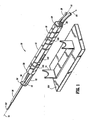
- the device (10) includes a housing (12) shaped in any one of a variety of configurations that is easily hand held or mounted for rotation to another structure such as the cradle (14) shown in Fig. 1 .
- the housing (12) is preferably generally elongated so as to define a longitudinal axis (16) therethrough.
- the material of the housing (12) may be any one of a variety of materials, including metals or plastics, suitable for use with medical devices and of sufficient strength and stiffness to perform as described herein. Since in the preferred embodiment the entire housing (12) and its inner components are intended to be disposed after use with a single patient, it is desirable that the housing (12) comprise an inexpensive material.
- the housing (12) of the preferred embodiment is provided with rotational position indicia (18) for locating the housing (12) in selective rotational positions relative to the patient or to the cradle (14), as will be described below.
- a drive cable port (22) and a vacuum port (24) are positioned on the distal end face (25).
- the drive cable port (22) receives a drive cable end (26) of a drive cable (80) and the vacuum port (24) receives a vacuum conduit (28), the function of each being described below.
- the distal end (30) of the housing (12) includes an extension arm (32) and a distal support (34) forming a tissue specimen retrieval zone (36) proximally adjacent to the distal support (34).
- a radiolucent tube (38) is mounted to the distal end (30) of the housing (12) in a manner permitting adjustable extension distally from the housing (12), as will be described below.
- a sampling needle (40) and a rotational cutter (42) Extending from the distal end (30) of the housing (12), and passing through the distal support (34) are a sampling needle (40) and a rotational cutter (42).
- the cutter (42) is mounted within the housing (12) in a manner permitting it to move rotationally and axially relative to the housing (12).
- the needle (40) is mounted within the housing (12) in a manner permitting it to move axially relative to the housing (12), but which prevents relative rotation of the needle (40) relative to the housing (12).
- the housing (12) comprises a first half (41) and a second half (44), each being adapted to interfit with the other to form a single, enclosed housing (12).
- the cutter (42) comprises an elongated, hollow tube having a distal end (46) with a sharpened edge for cutting tissue, a proximal end (48), and a tissue sample retrieval window (50) located near the proximal end (48).
- the cutter (42) is preferably made of a metal or similar rigid material that may be sharpened at the distal end (46) edge for cutting tissue.
- a first cutter gear (52) is connected to the proximal end (48) of the cutter (42) in a fixed relationship to transmit rotational motion to the cutter (42).
- the first cutter gear (52) may be connected to the cutter (42) by various suitable means including, as shown, a distal extension (54) that can be welded, press-fit or otherwise attached to the cutter (42).
- the first cutter gear (52) and the internal gear (56) are sized so that the first cutter gear (52) is positioned inside the internal gear (56).
- the number and ratio of gear teeth may vary according to desired output.
- the first cutter gear (52) is adapted to translate longitudinally inside of the internal gear (56) in order to facilitate advancement or retraction of the cutter (42) in the longitudinal direction relative to the housing (12).
- the internal gear (56) is mounted in the housing (12) in such a manner that the distal end (58) of the internal gear (56) abuts a first stop plate (60) fixed internally in the housing (12).
- the proximal end (62) of the internal gear (56) abuts the distal end face (64) of the gear case distal end (66) which is mounted inside the housing (12) in a non-moving manner which will be described below.
- the second cutter gear (68) is fixedly mounted directly to the distal end (70) of a cutter drive shaft (72).
- Fixedly mounted to the proximal end (74) of the cutter drive shaft (72) is a third cutter gear (76).
- the third cutter gear (76) when driven, transmits rotational motion through the cutter shaft (72) to the second cutter gear (68) and, thus, the internal gear (62), the first cutter gear (52) and, finally, the cutter (42).
- Rotational motion is imparted on the third cutter gear (76) by the master drive gear (78) which is driven by the drive cable (80) and housed in the cable housing (82) having a cable housing end (84).
- the drive cable (80) is rotationally driven by a conventional motor (86) or other drive means located remotely.
- the drive cable (80) is moved axially relative to the housing (12) by conventional means such as a solenoid or other type of linear actuator (88).
- the linear actuator (88) may, for example, include a push-pull piston (90) adapted to engage a disc or collar (92) that is crimped or otherwise fastened to the cable (80).
- the third cutter gear (76) can be selectively engaged or disengaged in order to selectively drive or not drive the cutter (42).
- a cutter advance gear (94) is provided and positioned within the housing (12) in such a manner so that it is simultaneously engaged by the master drive gear (78) when the master drive gear (78) engages the third cutter gear (76).
- the cutter advance gear (94) cooperates with additional components, as described below, which convert the rotational motion of the master drive gear (78) into linear motion in order to extend or retract the cutter (42) in a linear fashion.
- the cutter advance gear (94) is connected to a cutter advance shaft (96) by a spring clutch (98) which transmits rotational motion from the gear (92) to the shaft (96) in order to linearly advance or retract a lead nut (99) along a threaded section (100) of the shaft (96).
- the lead nut (99) has an extension arm (102) that extends distally through the gear case distal end (66) so that the distal end (104) of the extension arm (102) abuts the proximal face (106) of the first cutter gear (52).
- the lead nut (99) translates distally, thereby pushing the first cutter gear (52) and hence the cutter (42) so that they move distally relative to the internal gear (56) and the housing (12).
- the spring clutch (98) is selected so that it will allow relative slippage between the cutter advance shaft (96) and the cutter advance gear (92) if a predetermined axial resistance force is applied to the cutter (42).
- the cutter (42) will slow or stop moving in the axial direction, while continuing to rotate, until the resistance is diminished or overcome.
- An extension flag (108) of the spring clutch (98) and a retaining clip (110) enable it to be connected to the cutter advance gear (92).
- reversing the direction of rotation of the master drive gear (78) will, in turn, control the rotational and linear movement direction of the cutter (42) in accordance with the operation of the device as will be described below.
- a spring (112) biased on its distal end (114) by a second stop plate (116) and on its proximal end (118) by the distal face (120) of the first cutter gear (52) will push the first cutter gear (52) and the cutter (42) back in the proximal direction.
- the rate of movement in this manner will be dictated by the retreat of the lead nut (99) since it abuts the proximal end (106) of the first cutter gear (52).
- Advancement or retraction of the needle (40) in accordance with operation as described below, is activated by positioning the master drive gear (78) in engagement with the needle drive gear (122). As described above, the master drive gear (78) is moved axially relative to the housing (12) and, thus, can be selectively engaged with the needle drive gear (122). As shown in Fig. 3 , the needle drive gear (122) is offset from the third cutter gear (76) and the cutter advance gear (94) so that it can be engaged only when the two latter gears are not engaged, and vice-versa. When the master drive gear (78) engages the needle drive gear (122), rotational motion from the master drive gear (78) is transmitted through the needle drive gear (122) to the needle leadscrew (124) to which the needle drive gear (122) is fixed.
- the leadscrew (124) is threaded so that, when rotated, it causes a toggle nut (126) having internal threads (128) and positioned thereon to translate linearly along the leadscrew (124). Depending on the direction of rotation of the master drive gear (78), the toggle nut (126) will advance distally or retreat proximally along the leadscrew (124).
- the toggle nut (126) has two flags (130, 132) that extend generally radially and that are offset from each other axially as shown.
- the first flag (130) of the toggle nut (126) is positioned relative to the needle (40) in order to selectively engage the distal end face (134) of the needle flange (136).
- the needle flange (136) is fixedly attached to the proximal end (138) of the needle (40).
- the first flag (130) selectively engages or disengages the needle flange (136) by being rotated into or out or axial alignment with a portion of the needle flange (136).
- the first flag (130) When positioned for engagement with the flange (136), the first flag (130) will pull the flange (136) and needle (40) in a retracted, proximal direction as the toggle nut (126) moves proximally along the leadscrew (124) as described above.
- the second flag (132) of the toggle nut (126) is positioned relative to the needle (40) in order to selectively engage the proximal end face (134) of the needle flange (136).
- the needle flange (136) is fixedly attached to the proximal end (140) of the needle (40).
- the second flag (132) selectively engages or disengages the needle flange (136) by being rotated into or out or axial alignment with a portion of the needle flange (136).
- the second flag (132) When positioned for engagement with the flange (136), the second flag (132) will push the flange (136) and needle (40) in an extended, distal direction as the toggle nut (126) moves distally along the leadscrew (124) as described above.
- the flags (130, 132) are offset angularly so that the first flag (130), being located distally of the second flag (132), may be positioned for alignment with the flange (136) while the second flag (132) is positioned out of alignment with the flange (136). This facilitates the optional firing mode of the needle (40) that will be described below, by keeping the second flag (132) out of the way of the flange (136) during firing.
- the needle (40) and the attached flange (136) are telescopically received over the distal end (142) of the vacuum tube (144) for relative axial movement with respect thereto.
- the vacuum tube (144) remains fixed with respect to the housing (12) when the needle (40) is moved axially as described above.
- the proximal end (146) of the vacuum tube (144) is attached to a vacuum conduit (28) that is attached to a remote vacuum pressure source (150) of a conventional type.
- the needle (40) has a sharpened needle tip (152) adapted to penetrate or cut into tissue. Adjacent to the tip (152) is a tissue sample basket (154).
- the sample basket (154) is provided with holes (156) for applying suction to a tissue sample received in the basket (154). The suction is provided by through the vacuum tube (144).
- the internal components described above are housed within the housing (12) and a proximal end cap (158) forms the proximal end (20) cap of the housing.
- a toggle nut stop (160) is used to limit proximal movement of the toggle nut (126) and, thus, the needle (40). Distal movement of the toggle nut (126) and the needle (40) are limited by the proximal face (162) of the gear case distal end (163).
- the gear case proximal end (164) comprises a plate having series of holes (168, 170, 172, 174).
- the gear case (66) is positioned in the housing (12) toward the proximal.
- An first, central hole (168) receives the vacuum tube (144) and needle (40).
- the needle (40) extends through a central hole (176) in the distal end (162) of the gear case (66) and through a central hole (178) of the distal support (34).
- a radiolucent slide (180) having a central hole (182) aligned with the distal support central hole(178) is provided and receives the needle (40) therethrough.
- the slide (180) is fixed to the radiolucent tube (38) and enables it to be adjusted relative to the housing (12) in the axial direction in accordance with operation as described below.
- the four remaining holes rotationally support, respectively, the needle drive gear (122), the master drive gear (78), the third cutter gear (76), and the cutter advance gear (94).
- the tissue sampling device (10) is used to retrieve one or more tissue samples from a patient.
- tissue sampling device (10) is used to retrieve one or more tissue samples from a patient.
- tissue sampling device (10) In a biopsy retrieval operation, for example, it may be desired to take more than one tissue sample from a patient to locate one or more lesions.
- tissue retrieval procedure such as a breast biopsy procedure
- a patient is positioned on or next to a commercially available biopsy table or other positioning and imaging apparatus.
- imaging technology such as ultrasound
- a physician locates a desired target area for tissue sample retrieval.
- the device (10) may either be held in hand by a physician or it may be mounted to a cradle (14) which is mounted to a moveable carriage (184) as shown in Fig. 1 .
- the carriage (184) is part of an imaging table or other commercially known positioning device.
- the device (10) has bearing grooves (186) designed to cooperate with the cradle (14) to hold the device (10) within the cradle (14) in a manner permitting rotational movement with little friction.
- the initial step to obtaining a tissue sample requires introducing the needle tip (152) into and through the skin of the patient.
- the needle tip (152) may be advanced into and through the skin in one of two ways.
- a first way is to merely push the device forward by hand, using only manual force. The physician may monitor position during such introduction of the needle tip (152) using ultrasound imaging.
- Another way to advance the needle tip (152) into and through the skin is to advance a mechanical carriage (184) which holds the device (10) and thus the needle (152) relative therewith.
- imaging means or predetermined coordinates associated with carriage position the needle tip (152) can be advance to a target zone.
- the needle tip (152) After introduction of the needle tip (152) into and through the skin, the needle tip (152) is advanced further by either of the means described in the preceding paragraph until the needle tip (152) is adjacent to the tissue sample target zone (190) as shown in Fig. 4A .
- the needle tip (152) is advanced by either means so that the tissue sample receiving basket (154) is positioned within the target zone (190) as shown in Fig. 4B .
- the needle tip (152) may be advanced into the target zone (190) by the optional firing mode.
- the tip (152) is advanced relative to the housing (12) by a predetermined distance in a rapid fire manner so as to ensure cutting and penetration into a tissue region, rather than pushing the tissue out of the way of the needle tip (152).
- a modular firing mechanism (192) having a spring-loaded firing hammer (194) is positioned with the hammer (194) in the firing port (196, Fig.1 ) of the housing (12).
- the hammer (194) lines up proximally to the needle flange (136) so that when the firing mechanism (192) is fired by pulling its trigger (198), the hammer (194) pushes the flange (136) and needle tip (152) rapidly in the distal direction.
- the flags (130, 132) are positioned so that the first flag (130) is positioned for alignment with the flange (136) while the second flag (132) is positioned out of alignment with the flange (136), as described above. This keeps the second flag (132) out of the way of the flange (136) during firing.
- the device (10) is preferably shipped in its original, unused state so that the flags (130, 132) are in the alignment described immediately above.
- the position of the flags (130, 132) is controlled by rotating the leadscrew (124) in one direction or the other, as the toggle nut (126) engages the leadscrew (124) with enough friction to cause it to rotate with the leadscrew (124) for a limited rotational distance until it makes contact on either side and then the leadscrew (124) rotates relative to the toggle nut (126) to cause it to advance linearly along the leadscrew (124).
- Rotation of the leadscrew (124) may be caused by activating an electronic switch (200), which may be mounted on the housing (12) or remotely, to selectively activate a bi-directional, remote rotational motor (86).
- the motor (86) rotates the drive cable (80).
- the drive cable (80) is moved axially relative to the housing (12) by conventional means such as a solenoid or other type of linear actuator (88), which can be activated by an electronic switch (204) located on the housing (12) or remotely.
- the cutter (42) is moved back away from the needle tip (154) by mechanical components described above in order to expose the basket (154) to the tissue to be sampled as shown in Fig. 4C .
- the step of moving the cutter (42) may be initiated by activating an electronic switch (206) located on the housing (12) or located remotely.
- an electronic switch (206) located on the housing (12) or located remotely.
- suction may be applied through the holes (156) via the vacuum tube (144) and vacuum source (150) as described above.
- the vacuum pressure may be initiated by an electronic switch (208) located on the housing (12) or remotely.
- the cutter (42) Shortly after vacuum pressure is activated, and tissue is drawn into the basket (154), the cutter (42) may be rotated and advanced linearly by mechanical means as described above until it reaches the position shown in Fig. 4D .
- the sequence of activating the vacuum and moving the cutter (42) may be initiated by a single electronic switch (210) located on the housing (12) or remotely.
- tissue sample will have been cut and captured in the basket (154).
- the cutter (42) now in a distally extended position, is stopped to hold the sample site and the needle (40) is retracted so that the basket (154) is positioned in the tissue specimen retrieval zone (36) as shown in Fig. 4E for removal of the tissue sample (212).
- the tissue sample (212) may be grasped or removed from the basket (154) by forceps or other known means.
- the needle (40) is advanced by activating an electronic switch (214) which is located on the housing (12) or remotely which, in turn, activates the mechanical components as described above for linear advancement of the needle (40) using the leadscrew (124) and toggle nut (126).
- the needle tip (152) is advanced distally of the cutter (42) as shown in Fig. 4B .
- the device (10) can then be adjusted linearly or rotationally relative to the patient and the tissue target zone (190).
- the next sequence of retrieving a tissue sample may be initiated by moving the cutter (42) back away from the needle tip (152) in order to expose the basket (154).
- the vacuum, cutting and tissue sequences as described above are repeated to obtain another sample.
- the above described procedure can be repeated as many times as needed to obtain a desired number of samples.
- the master drive gear (78) and drive cable (80) are detached from the device (10) so that the remainder of components of the device (10) can be discarded.
- the vacuum conduit (148) is removed from the vacuum source (150) and discarded along with the device (10).
- the drive cable (80) can be attached to a new device of the same type as the device (10) described herein and another vacuum conduit (148) can be attached between the device (10) and the vacuum source (150) for subsequent use with another patient.
- the slide (180) fixed to the radiolucent tube (38) can be extended distally with respect to the housing (12) to a predetermined distance so as to partially block the sample basket (154) when the needle (40) is in an extended position. Because the tube (38) and slide (180) are radiolucent, neither will interfere with the ability to view the surrounding site during a procedure.
Claims (4)
- Dispositif d'élimination de tissus (10) pour éliminer sélectivement une ou plusieurs portions de tissus d'un patient médical, ledit dispositif comprenant :un boîtier (2) ;un élément de perforation (40) pour perforer les tissus dudit patient ;une section réceptrice de tissus (154) dudit élément de perforation pour recevoir une portion desdits tissus ;un élément de coupe (42) pour sectionner sélectivement ladite portion de tissus tandis qu'elle est maintenue dans ladite section de réception ; et caractérisé par :un seul câble d'entraînement (80) fixé en service, à une extrémité, audit boîtier et, à une autre extrémité, à des moyens d'entraînement éloignés (86) pour déplacer ledit élément de coupe de manière à l'amener à sectionner ladite portion de tissus et pour déplacer sélectivement ledit élément de perforation par rapport audit boîtier.
- Dispositif selon la revendication 1, comprenant par tailleurs :une roue dentée d'entraînement principale (78) fixée audit câble d'entraînement unique, ladite roue dentée d'entraînement principale étant à même de s'engager sélectivement et opérationnellement sur une roue dentée d'entraînement (76, 122) associée à chacun dudit élément de perforation et dudit élément de coupe pour transmettre un mouvement desdits moyens d'entraînement éloignés audit élément de perforation et audit dispositif de coupe.
- Dispositif selon la revendication 3, dans lequel :lesdits moyens d'entraînement éloignés comprennent un seul moteur rotatif (86) qui est à même de tourner dans deux sens.
- Dispositif d'élimination de tissus selon la revendication 1, 2 ou 3, comprenant :une portion jetable comprenant :le boîtier ;l'élément de perforation ;la section réceptrice de tissus dudit élément de perforation ; etl'élément de coupe ; etune portion réutilisable comprenant :le câble d'entraînement unique fixé en service, à une extrémité, audit boîtier et, à une autre extrémité, auxdits moyens d'entraînement éloignés.
Applications Claiming Priority (3)
| Application Number | Priority Date | Filing Date | Title |
|---|---|---|---|
| US25314700P | 2000-11-27 | 2000-11-27 | |
| US253147P | 2000-11-27 | ||
| PCT/US2001/048629 WO2002041787A2 (fr) | 2000-11-27 | 2001-11-12 | Appareil et procede d'echantillonnage et d'elimination de tissus |
Publications (2)
| Publication Number | Publication Date |
|---|---|
| EP1339326A2 EP1339326A2 (fr) | 2003-09-03 |
| EP1339326B1 true EP1339326B1 (fr) | 2013-03-06 |
Family
ID=22959061
Family Applications (1)
| Application Number | Title | Priority Date | Filing Date |
|---|---|---|---|
| EP01990207A Expired - Lifetime EP1339326B1 (fr) | 2000-11-27 | 2001-11-12 | Appareil d'echantillonnage et d'elimination de tissus |
Country Status (6)
| Country | Link |
|---|---|
| US (2) | US6860860B2 (fr) |
| EP (1) | EP1339326B1 (fr) |
| JP (1) | JP3996057B2 (fr) |
| AU (2) | AU2907002A (fr) |
| CA (1) | CA2429040C (fr) |
| WO (1) | WO2002041787A2 (fr) |
Families Citing this family (152)
| Publication number | Priority date | Publication date | Assignee | Title |
|---|---|---|---|---|
| ITCE990004A1 (it) | 1999-10-25 | 2000-01-25 | Mario Immacolato Paternuosto | Valve per pinza da biopsia in endoscopia digestiva |
| US6814743B2 (en) | 2001-12-26 | 2004-11-09 | Origin Medsystems, Inc. | Temporary seal and method for facilitating anastomosis |
| JP4342319B2 (ja) | 2002-03-19 | 2009-10-14 | バード ダブリン アイティーシー リミティッド | 生検装置、並びに生検装置に使用可能な生検針モジュール |
| CA2479339C (fr) | 2002-03-19 | 2013-03-12 | Bard Dublin Itc Limited | Dispositif pour biopsie sous vide |
| US9451968B2 (en) | 2002-05-31 | 2016-09-27 | Vidacare LLC | Powered drivers, intraosseous devices and methods to access bone marrow |
| US11337728B2 (en) | 2002-05-31 | 2022-05-24 | Teleflex Life Sciences Limited | Powered drivers, intraosseous devices and methods to access bone marrow |
| US20070049945A1 (en) * | 2002-05-31 | 2007-03-01 | Miller Larry J | Apparatus and methods to install, support and/or monitor performance of intraosseous devices |
| US8641715B2 (en) | 2002-05-31 | 2014-02-04 | Vidacare Corporation | Manual intraosseous device |
| US11298202B2 (en) | 2002-05-31 | 2022-04-12 | Teleflex Life Sciences Limited | Biopsy devices and related methods |
| US9072543B2 (en) | 2002-05-31 | 2015-07-07 | Vidacare LLC | Vascular access kits and methods |
| WO2008033872A2 (fr) * | 2006-09-12 | 2008-03-20 | Vidacare Corporation | Dispositifs pour biopsie et procédé associé |
| US20030225344A1 (en) | 2002-05-31 | 2003-12-04 | Vidacare Corporation | Apparatus and method to access the bone marrow for oncology and stem cell applications |
| US9314228B2 (en) * | 2002-05-31 | 2016-04-19 | Vidacare LLC | Apparatus and method for accessing the bone marrow |
| US8142365B2 (en) * | 2002-05-31 | 2012-03-27 | Vidacare Corporation | Apparatus and method for accessing the bone marrow of the sternum |
| US10973545B2 (en) | 2002-05-31 | 2021-04-13 | Teleflex Life Sciences Limited | Powered drivers, intraosseous devices and methods to access bone marrow |
| US8690791B2 (en) | 2002-05-31 | 2014-04-08 | Vidacare Corporation | Apparatus and method to access the bone marrow |
| US8668698B2 (en) * | 2002-05-31 | 2014-03-11 | Vidacare Corporation | Assembly for coupling powered driver with intraosseous device |
| US7951089B2 (en) * | 2002-05-31 | 2011-05-31 | Vidacare Corporation | Apparatus and methods to harvest bone and bone marrow |
| US7811260B2 (en) | 2002-05-31 | 2010-10-12 | Vidacare Corporation | Apparatus and method to inject fluids into bone marrow and other target sites |
| US10973532B2 (en) | 2002-05-31 | 2021-04-13 | Teleflex Life Sciences Limited | Powered drivers, intraosseous devices and methods to access bone marrow |
| DE10314240A1 (de) | 2003-03-29 | 2004-10-07 | Bard Dublin Itc Ltd., Crawley | Druckerzeugungseinheit |
| US9504477B2 (en) | 2003-05-30 | 2016-11-29 | Vidacare LLC | Powered driver |
| ITPO20030007A1 (it) * | 2003-06-13 | 2004-12-14 | Aurelio Gironi | Mezzo agobioptico per prelievi multipli |
| US7960935B2 (en) | 2003-07-08 | 2011-06-14 | The Board Of Regents Of The University Of Nebraska | Robotic devices with agent delivery components and related methods |
| US7588545B2 (en) | 2003-09-10 | 2009-09-15 | Boston Scientific Scimed, Inc. | Forceps and collection assembly with accompanying mechanisms and related methods of use |
| US7942896B2 (en) | 2003-11-25 | 2011-05-17 | Scimed Life Systems, Inc. | Forceps and collection assembly and related methods of use and manufacture |
| US7815642B2 (en) * | 2004-01-26 | 2010-10-19 | Vidacare Corporation | Impact-driven intraosseous needle |
| CN101474088B (zh) | 2004-01-26 | 2011-12-14 | 维达保健公司 | 手动式骨内器械 |
| PL1768571T3 (pl) | 2004-07-09 | 2012-08-31 | Bard Peripheral Vascular Inc | Mechanizm uruchamiający dla urządzenia biopsyjnego |
| US7296442B2 (en) * | 2004-07-15 | 2007-11-20 | Owens-Brockway Glass Container Inc. | Neck ring cooling |
| US8998848B2 (en) * | 2004-11-12 | 2015-04-07 | Vidacare LLC | Intraosseous device and methods for accessing bone marrow in the sternum and other target areas |
| US7611474B2 (en) * | 2004-12-29 | 2009-11-03 | Ethicon Endo-Surgery, Inc. | Core sampling biopsy device with short coupled MRI-compatible driver |
| US7517321B2 (en) | 2005-01-31 | 2009-04-14 | C. R. Bard, Inc. | Quick cycle biopsy system |
| US7955345B2 (en) * | 2005-04-01 | 2011-06-07 | Nexgen Medical Systems, Inc. | Thrombus removal system and process |
| US8603122B2 (en) | 2005-04-01 | 2013-12-10 | Nexgen Medical Systems, Incorporated | Thrombus removal system and process |
| US7955344B2 (en) * | 2005-04-01 | 2011-06-07 | Nexgen Medical Systems, Inc. | Thrombus removal system and process |
| USRE47376E1 (en) | 2005-04-01 | 2019-05-07 | Nexgen Medical Systems, Incorporated | Thrombus removal system and process |
| WO2006119426A2 (fr) * | 2005-05-03 | 2006-11-09 | Regents Of The University Of California | Systemes de biopsie pour tomographie par ordinateur (ct) |
| US7762960B2 (en) | 2005-05-13 | 2010-07-27 | Boston Scientific Scimed, Inc. | Biopsy forceps assemblies |
| US7867173B2 (en) | 2005-08-05 | 2011-01-11 | Devicor Medical Products, Inc. | Biopsy device with replaceable probe and incorporating vibration insertion assist and static vacuum source sample stacking retrieval |
| JP4955681B2 (ja) | 2005-08-10 | 2012-06-20 | シー・アール・バード・インコーポレーテッド | 直線駆動装置を有する単一挿入複数サンプリング生検デバイス |
| JP5102207B2 (ja) | 2005-08-10 | 2012-12-19 | シー・アール・バード・インコーポレーテッド | 種々の輸送システム及び統合マーカで使用可能な単一挿入複数サンプリング生検デバイス |
| US8267868B2 (en) | 2005-08-10 | 2012-09-18 | C. R. Bard, Inc. | Single-insertion, multiple sample biopsy device with integrated markers |
| US20070149881A1 (en) * | 2005-12-22 | 2007-06-28 | Rabin Barry H | Ultrasonically Powered Medical Devices and Systems, and Methods and Uses Thereof |
| US20070156125A1 (en) * | 2005-12-30 | 2007-07-05 | Russell Delonzor | Encodable cryogenic device |
| US7670299B2 (en) * | 2006-03-07 | 2010-03-02 | Ethincon Endo-Surgery, Inc. | Device for minimally invasive internal tissue removal |
| US7806834B2 (en) * | 2006-03-07 | 2010-10-05 | Devicor Medical Products, Inc. | Device for minimally invasive internal tissue removal |
| US7465278B2 (en) * | 2006-03-29 | 2008-12-16 | Ethicon Endo-Surgery, Inc. | Device for minimally invasive internal tissue removal |
| US7585547B2 (en) * | 2006-04-13 | 2009-09-08 | Solopower, Inc. | Method and apparatus to form thin layers of materials on a base |
| US20070270714A1 (en) * | 2006-05-19 | 2007-11-22 | E-Z-Em, Inc. | System and method for tissue specimen collection |
| US9579088B2 (en) | 2007-02-20 | 2017-02-28 | Board Of Regents Of The University Of Nebraska | Methods, systems, and devices for surgical visualization and device manipulation |
| CA2655964C (fr) | 2006-06-22 | 2014-10-28 | Board Of Regents Of The University Of Nebraska | Dispositifs robotiques pouvant etre couples magnetiquement et procedes associes |
| US8679096B2 (en) | 2007-06-21 | 2014-03-25 | Board Of Regents Of The University Of Nebraska | Multifunctional operational component for robotic devices |
| EP3417792B1 (fr) | 2006-08-21 | 2022-03-02 | C. R. Bard, Inc. | Aiguille de biopsie portative autonome |
| ES2609923T3 (es) * | 2006-09-12 | 2017-04-25 | Vidacare LLC | Aparato para biopsia y aspiración de médula ósea |
| US8944069B2 (en) | 2006-09-12 | 2015-02-03 | Vidacare Corporation | Assemblies for coupling intraosseous (IO) devices to powered drivers |
| EP3189787B1 (fr) | 2006-09-12 | 2019-01-09 | Teleflex Medical Devices S.à.r.l. | Plateaux pour opérations médicales et procédés associés |
| EP2068743B1 (fr) | 2006-09-12 | 2017-03-15 | Vidacare LLC | Plateaux pour opérations médicales, kits et procédés associés |
| PT2086418E (pt) | 2006-10-06 | 2011-03-29 | Bard Peripheral Vascular Inc | Sistema de manuseamento de tecidos com reduzida exposição do operador |
| EP2086417B1 (fr) | 2006-10-24 | 2015-07-01 | C.R.Bard, Inc. | Aiguille de biopsie à faible facteur de forme pour échantillons de grande taille |
| US8974410B2 (en) | 2006-10-30 | 2015-03-10 | Vidacare LLC | Apparatus and methods to communicate fluids and/or support intraosseous devices |
| US9028520B2 (en) | 2006-12-22 | 2015-05-12 | The Spectranetics Corporation | Tissue separating systems and methods |
| US8961551B2 (en) | 2006-12-22 | 2015-02-24 | The Spectranetics Corporation | Retractable separating systems and methods |
| WO2009014917A2 (fr) | 2007-07-12 | 2009-01-29 | Board Of Regents Of The University Of Nebraska | Procédés et systèmes d'actionnement dans des dispositifs robotiques |
| WO2009023851A1 (fr) | 2007-08-15 | 2009-02-19 | Board Of Regents Of The University Of Nebraska | Dispositifs médicaux modulaires et coopératifs et systèmes et procédés apparentés |
| JP2010536435A (ja) | 2007-08-15 | 2010-12-02 | ボード オブ リージェンツ オブ ザ ユニバーシティ オブ ネブラスカ | 医療用膨張、取り付けおよび送達装置、ならびに関連する方法 |
| US20090112119A1 (en) * | 2007-10-31 | 2009-04-30 | Kim Stanley I | Rotating biopsy device and biopsy robot |
| US8241225B2 (en) | 2007-12-20 | 2012-08-14 | C. R. Bard, Inc. | Biopsy device |
| US7854706B2 (en) | 2007-12-27 | 2010-12-21 | Devicor Medical Products, Inc. | Clutch and valving system for tetherless biopsy device |
| US20090253997A1 (en) * | 2008-04-03 | 2009-10-08 | Convergent Medical Solutions, Inc. | Skin biopsy with automated lesion stabilization and resection |
| US20090253998A1 (en) * | 2008-04-03 | 2009-10-08 | Convergent Medical Solutions, Inc. | Skin biopsy with suturing prior to resection |
| US20100081928A1 (en) * | 2008-09-29 | 2010-04-01 | Searete Llc, A Limited Liability Corporation Of The State Of Delaware | Histological Facilitation systems and methods |
| US9782565B2 (en) | 2008-10-01 | 2017-10-10 | Covidien Lp | Endoscopic ultrasound-guided biliary access system |
| US9332973B2 (en) | 2008-10-01 | 2016-05-10 | Covidien Lp | Needle biopsy device with exchangeable needle and integrated needle protection |
| US8968210B2 (en) | 2008-10-01 | 2015-03-03 | Covidien LLP | Device for needle biopsy with integrated needle protection |
| US11298113B2 (en) | 2008-10-01 | 2022-04-12 | Covidien Lp | Device for needle biopsy with integrated needle protection |
| US9186128B2 (en) | 2008-10-01 | 2015-11-17 | Covidien Lp | Needle biopsy device |
| WO2010107424A1 (fr) | 2009-03-16 | 2010-09-23 | C.R. Bard, Inc. | Dispositif de biopsie comprenant une coupe rotative |
| DE102009016859B4 (de) * | 2009-04-08 | 2018-06-14 | Erbe Elektromedizin Gmbh | Wasserstrahlchirurgieinstrument |
| MX339049B (es) | 2009-04-15 | 2016-05-06 | Bard Inc C R | Aparato de biopsia que tiene una gestion de fluido integrada. |
| US8206316B2 (en) | 2009-06-12 | 2012-06-26 | Devicor Medical Products, Inc. | Tetherless biopsy device with reusable portion |
| EP3572002A1 (fr) | 2009-08-12 | 2019-11-27 | C.R. Bard Inc. | Appareil de biopsie comprenant un mécanisme à molette intégré qui permet de faire tourner manuellement une canule pour biopsie |
| US8085488B2 (en) * | 2009-08-27 | 2011-12-27 | Hitachi Global Storage Technologies Netherlands B.V. | Predicting operational problems in a hard-disk drive (HDD) |
| USD640977S1 (en) | 2009-09-25 | 2011-07-05 | C. R. Bard, Inc. | Charging station for a battery operated biopsy device |
| US8485989B2 (en) | 2009-09-01 | 2013-07-16 | Bard Peripheral Vascular, Inc. | Biopsy apparatus having a tissue sample retrieval mechanism |
| US8430824B2 (en) | 2009-10-29 | 2013-04-30 | Bard Peripheral Vascular, Inc. | Biopsy driver assembly having a control circuit for conserving battery power |
| US8597206B2 (en) | 2009-10-12 | 2013-12-03 | Bard Peripheral Vascular, Inc. | Biopsy probe assembly having a mechanism to prevent misalignment of components prior to installation |
| KR101999802B1 (ko) | 2009-11-13 | 2019-07-12 | 인튜어티브 서지컬 오퍼레이션즈 인코포레이티드 | 독립적으로 회전하는 부재 내의 병렬 구동 샤프트들을 위한 모터 연접부 |
| US20110118708A1 (en) * | 2009-11-13 | 2011-05-19 | Intuitive Surgical Operations, Inc. | Double universal joint |
| WO2011060315A2 (fr) | 2009-11-13 | 2011-05-19 | Intuitive Surgical Operations, Inc. | Outil chirurgical avec un tourillon compact |
| CN102596058B (zh) | 2009-11-13 | 2015-10-21 | 直观外科手术操作公司 | 具有复设的闭合机构的末端执行器 |
| WO2011075693A1 (fr) | 2009-12-17 | 2011-06-23 | Board Of Regents Of The University Of Nebraska | Dispositifs médicaux modulaires et utilisables en interaction et systèmes et procédés afférents |
| WO2011119872A1 (fr) | 2010-03-24 | 2011-09-29 | Nexgen Medical Systems, Inc. | Système et procédé d'élimination de thrombus |
| US8529467B2 (en) | 2010-03-30 | 2013-09-10 | Siteselect Medical Technologies, Inc. | Tissue excision device with a collapsible stylet |
| US8968267B2 (en) | 2010-08-06 | 2015-03-03 | Board Of Regents Of The University Of Nebraska | Methods and systems for handling or delivering materials for natural orifice surgery |
| US8764680B2 (en) * | 2010-11-01 | 2014-07-01 | Devicor Medical Products, Inc. | Handheld biopsy device with needle firing |
| US9968337B2 (en) * | 2010-12-20 | 2018-05-15 | Cook Medical Technologies Llc | Coring tissue biopsy needle and method of use |
| US9060781B2 (en) | 2011-06-10 | 2015-06-23 | Board Of Regents Of The University Of Nebraska | Methods, systems, and devices relating to surgical end effectors |
| JP6106169B2 (ja) | 2011-07-11 | 2017-03-29 | ボード オブ リージェンツ オブ ザ ユニバーシティ オブ ネブラスカ | 手術ロボットシステム |
| US8540645B2 (en) * | 2011-07-27 | 2013-09-24 | Suros Surgical Systems, Inc. | Needle biopsy device and related method |
| EP3970784A1 (fr) | 2012-01-10 | 2022-03-23 | Board of Regents of the University of Nebraska | Systèmes et dispositifs pour accès chirurgical et insertion chirurgicale |
| WO2013158072A1 (fr) | 2012-04-16 | 2013-10-24 | Hathaway Jeff M | Dispositif de biopsie |
| EP2844181B1 (fr) | 2012-05-01 | 2021-03-10 | Board of Regents of the University of Nebraska | Dispositif robotique à site unique et systèmes associés |
| US9010214B2 (en) | 2012-06-22 | 2015-04-21 | Board Of Regents Of The University Of Nebraska | Local control robotic surgical devices and related methods |
| US9347533B2 (en) | 2012-07-25 | 2016-05-24 | Cook Medical Technologies Llc | Rotational drive system for a biopsy member |
| US9770305B2 (en) | 2012-08-08 | 2017-09-26 | Board Of Regents Of The University Of Nebraska | Robotic surgical devices, systems, and related methods |
| JP2015526171A (ja) | 2012-08-08 | 2015-09-10 | ボード オブ リージェンツ オブ ザ ユニバーシティ オブ ネブラスカ | ロボット手術用デバイス、システム及び関連の方法 |
| US9724122B2 (en) | 2012-09-14 | 2017-08-08 | The Spectranetics Corporation | Expandable lead jacket |
| US9301735B2 (en) | 2012-12-19 | 2016-04-05 | Cook Medical Technologies Llc | Drive system for a biopsy member |
| US9291663B2 (en) | 2013-03-13 | 2016-03-22 | The Spectranetics Corporation | Alarm for lead insulation abnormality |
| US9456872B2 (en) | 2013-03-13 | 2016-10-04 | The Spectranetics Corporation | Laser ablation catheter |
| US10383691B2 (en) | 2013-03-13 | 2019-08-20 | The Spectranetics Corporation | Last catheter with helical internal lumen |
| US9283040B2 (en) | 2013-03-13 | 2016-03-15 | The Spectranetics Corporation | Device and method of ablative cutting with helical tip |
| US9883885B2 (en) | 2013-03-13 | 2018-02-06 | The Spectranetics Corporation | System and method of ablative cutting and pulsed vacuum aspiration |
| US9888966B2 (en) | 2013-03-14 | 2018-02-13 | Board Of Regents Of The University Of Nebraska | Methods, systems, and devices relating to force control surgical systems |
| US10835279B2 (en) | 2013-03-14 | 2020-11-17 | Spectranetics Llc | Distal end supported tissue slitting apparatus |
| WO2014160086A2 (fr) | 2013-03-14 | 2014-10-02 | Board Of Regents Of The University Of Nebraska | Procédés, systèmes et dispositifs associés à des dispositifs chirurgicaux robotiques, des effecteurs finaux et des unités de commande |
| US10448999B2 (en) | 2013-03-15 | 2019-10-22 | The Spectranetics Corporation | Surgical instrument for removing an implanted object |
| US10842532B2 (en) | 2013-03-15 | 2020-11-24 | Spectranetics Llc | Medical device for removing an implanted object |
| WO2014144220A1 (fr) | 2013-03-15 | 2014-09-18 | Board Of Regents Of The University Of Nebraska | Dispositifs chirurgicaux robotiques, systèmes et procédés apparentés |
| US9925366B2 (en) | 2013-03-15 | 2018-03-27 | The Spectranetics Corporation | Surgical instrument for removing an implanted object |
| US9603618B2 (en) | 2013-03-15 | 2017-03-28 | The Spectranetics Corporation | Medical device for removing an implanted object |
| US9668765B2 (en) | 2013-03-15 | 2017-06-06 | The Spectranetics Corporation | Retractable blade for lead removal device |
| WO2017048486A1 (fr) | 2013-03-15 | 2017-03-23 | The Spectranetics Corporation | Dispositif médical pour extraction d'un objet implanté, utilisant des tubes hypodermiques découpés au laser |
| EP3498176B1 (fr) | 2013-03-20 | 2021-04-28 | Bard Peripheral Vascular, Inc. | Dispositif de biopsie |
| WO2015009949A2 (fr) | 2013-07-17 | 2015-01-22 | Board Of Regents Of The University Of Nebraska | Dispositifs chirurgicaux robotiques, systèmes et procédés apparentés |
| JP6348587B2 (ja) | 2013-11-05 | 2018-06-27 | シー・アール・バード・インコーポレーテッドC R Bard Incorporated | 一体型吸引器を有する生検デバイス |
| WO2015134383A1 (fr) | 2014-03-03 | 2015-09-11 | The Spectranetics Corporation | Dispositif de coupe chirurgical à configurations multiples |
| US10405924B2 (en) | 2014-05-30 | 2019-09-10 | The Spectranetics Corporation | System and method of ablative cutting and vacuum aspiration through primary orifice and auxiliary side port |
| EP3868322A1 (fr) | 2014-09-12 | 2021-08-25 | Board of Regents of the University of Nebraska | Effecteurs à libération rapide et systèmes associés |
| CN105520756B (zh) * | 2014-09-29 | 2020-03-31 | 德昌电机(深圳)有限公司 | 医疗设备用驱动装置 |
| CA2967593C (fr) | 2014-11-11 | 2024-02-27 | Board Of Regents Of The University Of Nebraska | Dispositif robotise a modele d'articulation compacte, ainsi que systemes et procedes associes |
| USD765243S1 (en) | 2015-02-20 | 2016-08-30 | The Spectranetics Corporation | Medical device handle |
| USD770616S1 (en) | 2015-02-20 | 2016-11-01 | The Spectranetics Corporation | Medical device handle |
| EP3288467B1 (fr) | 2015-05-01 | 2022-01-05 | C. R. Bard, Inc. | Dispositif de biopsie |
| CN114027986A (zh) | 2015-08-03 | 2022-02-11 | 内布拉斯加大学董事会 | 机器人手术装置系统及相关方法 |
| US10751136B2 (en) | 2016-05-18 | 2020-08-25 | Virtual Incision Corporation | Robotic surgical devices, systems and related methods |
| JP2019524371A (ja) | 2016-08-25 | 2019-09-05 | ボード オブ リージェンツ オブ ザ ユニバーシティ オブ ネブラスカ | クイックリリースツールカプラ並びに関連するシステム及び方法 |
| US10702347B2 (en) | 2016-08-30 | 2020-07-07 | The Regents Of The University Of California | Robotic device with compact joint design and an additional degree of freedom and related systems and methods |
| KR102594842B1 (ko) * | 2016-10-12 | 2023-10-30 | 데비코어 메디컬 프로덕츠, 인코포레이티드 | 한 번의 삽입으로 다수의 검체를 채취하기 위한 중심 침 생검 장치 |
| CN115337111A (zh) | 2016-11-22 | 2022-11-15 | 内布拉斯加大学董事会 | 改进的粗定位装置及相关系统和方法 |
| CA3045462A1 (fr) | 2016-11-29 | 2018-06-07 | Virtual Incision Corporation | Dispositif de commande d'utilisateur a detection de presence d'utilisateur et systemes et procedes associes |
| WO2018112199A1 (fr) | 2016-12-14 | 2018-06-21 | Virtual Incision Corporation | Dispositif de fixation libérable destiné à être accouplé à des dispositifs médicaux et systèmes et procédés associés |
| KR102332370B1 (ko) * | 2017-05-12 | 2021-12-01 | 데비코어 메디컬 프로덕츠, 인코포레이티드 | 팁 보호기 및 장착 장치를 갖는 생검 디바이스 |
| US11116483B2 (en) | 2017-05-19 | 2021-09-14 | Merit Medical Systems, Inc. | Rotating biopsy needle |
| US11844500B2 (en) | 2017-05-19 | 2023-12-19 | Merit Medical Systems, Inc. | Semi-automatic biopsy needle device and methods of use |
| WO2018213611A1 (fr) | 2017-05-19 | 2018-11-22 | Merit Medical Systems, Inc. | Dispositifs aiguilles de biopsie et leurs procédés d'utilisation |
| CN111417333B (zh) | 2017-09-27 | 2023-08-29 | 虚拟切割有限公司 | 具有跟踪相机技术的机器人手术设备及相关系统和方法 |
| CN111770816B (zh) | 2018-01-05 | 2023-11-03 | 内布拉斯加大学董事会 | 具有紧凑型关节设计的单臂机器人装置及相关系统和方法 |
| CA3125742A1 (fr) | 2019-01-07 | 2020-07-16 | Virtual Incision Corporation | Systemes chirurgical assiste par robot, et dispositifs et procedes associes |
| US20210220003A1 (en) * | 2020-01-17 | 2021-07-22 | Covidien Lp | Tissue resecting instrument |
| CN117064456B (zh) * | 2023-10-17 | 2024-02-02 | 江西省水产科学研究所(江西省鄱阳湖渔业研究中心、江西省渔业资源生态环境监测中心) | 一种鲫鱼类免疫组织自动取样装置 |
Family Cites Families (155)
| Publication number | Priority date | Publication date | Assignee | Title |
|---|---|---|---|---|
| US737293A (en) | 1900-11-01 | 1903-08-25 | George H Summerfeldt | Veterinary surgical instrument. |
| US1167014A (en) | 1915-06-25 | 1916-01-04 | William R O'brien | Veterinary surgical instrument. |
| US1255330A (en) | 1917-07-18 | 1918-02-05 | David Morgan | Machine for making reinforced-concrete blocks. |
| US1585934A (en) | 1923-12-29 | 1926-05-25 | Radium Emanation Corp | Diagnostic needle |
| US1663761A (en) | 1927-02-07 | 1928-03-27 | George A Johnson | Surgical instrument |
| US1867624A (en) | 1930-04-01 | 1932-07-19 | Memorial Hospital For The Trea | Device for obtaining biopsy specimens |
| US2505358A (en) | 1949-04-20 | 1950-04-25 | Sklar Mfg Co Inc J | Double-cutting biopsy bistoury |
| US2705949A (en) | 1953-08-25 | 1955-04-12 | Silverman Irving | Biopsy needle |
| US2729210A (en) | 1954-06-22 | 1956-01-03 | Frank C Spencer | Medical instrument |
| US2919692A (en) | 1956-02-23 | 1960-01-05 | Ackermann Wolfgang | Vertebral trephine biopsy instruments |
| US3400708A (en) | 1965-11-24 | 1968-09-10 | Robert A. Scheidt | Cytologic endocrine evaluation device |
| US3477423A (en) | 1967-01-09 | 1969-11-11 | Baxter Laboratories Inc | Biopsy instrument |
| US3561429A (en) | 1968-05-23 | 1971-02-09 | Eversharp Inc | Instrument for obtaining a biopsy specimen |
| US3590808A (en) | 1968-09-04 | 1971-07-06 | Us Catheter & Instr Corp | Biopsy tool |
| US3732858A (en) | 1968-09-16 | 1973-05-15 | Surgical Design Corp | Apparatus for removing blood clots, cataracts and other objects from the eye |
| US3606878A (en) | 1968-10-04 | 1971-09-21 | Howard B Kellogg Jr | Needle instrument for extracting biopsy sections |
| US3844272A (en) | 1969-02-14 | 1974-10-29 | A Banko | Surgical instruments |
| US3734099A (en) | 1971-04-07 | 1973-05-22 | H Bender | Powered surgical cutter |
| US3929123A (en) | 1973-02-07 | 1975-12-30 | Khosrow Jamshidi | Muscle biopsy needle |
| AR196829A1 (es) | 1973-12-06 | 1974-02-19 | Halpern D | Instrumento quirurgico para biopsias |
| US3995619A (en) | 1975-10-14 | 1976-12-07 | Glatzer Stephen G | Combination subcutaneous suture remover, biopsy sampler and syringe |
| US4099518A (en) | 1976-05-10 | 1978-07-11 | Baylis Shelby M | Biopsy apparatus |
| US4243048A (en) | 1976-09-21 | 1981-01-06 | Jim Zegeer | Biopsy device |
| US4200106A (en) | 1977-10-11 | 1980-04-29 | Dinkelkamp Henry T | Fixed arc cyclic ophthalmic surgical instrument |
| US4203444A (en) | 1977-11-07 | 1980-05-20 | Dyonics, Inc. | Surgical instrument suitable for closed surgery such as of the knee |
| US4246902A (en) | 1978-03-10 | 1981-01-27 | Miguel Martinez | Surgical cutting instrument |
| US4220155A (en) | 1978-05-11 | 1980-09-02 | Colorado State University Research Foundation | Apparatus for spaying large animals |
| US4210146A (en) | 1978-06-01 | 1980-07-01 | Anton Banko | Surgical instrument with flexible blade |
| GB2022421B (en) | 1978-06-08 | 1982-09-15 | Wolf Gmbh Richard | Devices for obtaining tissure samples |
| US4513745A (en) | 1978-06-21 | 1985-04-30 | Amoils Selig P | Surgical instruments and methods particularly adapted for intra-ocular cutting and the like |
| US4274414A (en) | 1979-02-21 | 1981-06-23 | Dyonics, Inc. | Surgical instrument |
| US4314560A (en) | 1979-11-28 | 1982-02-09 | Helfgott Maxwell A | Powered handpiece for endophthalmic surgery |
| US4340066A (en) | 1980-02-01 | 1982-07-20 | Sherwood Medical Industries Inc. | Medical device for collecting a body sample |
| US4306570A (en) | 1980-08-20 | 1981-12-22 | Matthews Larry S | Counter rotating biopsy needle |
| US4396021A (en) | 1980-12-15 | 1983-08-02 | Baumgartner George C | Surgical instrument and process |
| US4517977A (en) | 1981-07-24 | 1985-05-21 | Unisearch Limited | Co-axial tube surgical infusion/suction cutter tip |
| US4461305A (en) | 1981-09-04 | 1984-07-24 | Cibley Leonard J | Automated biopsy device |
| US4403617A (en) | 1981-09-08 | 1983-09-13 | Waters Instruments, Inc. | Biopsy needle |
| US4530356A (en) | 1983-02-08 | 1985-07-23 | Helfgott Maxwell A | Ophthalmic surgical instrument with beveled tip |
| US4660267A (en) | 1983-03-08 | 1987-04-28 | Richards Medical Company | Method for fabricating an arthroscopic shaver |
| US4603694A (en) | 1983-03-08 | 1986-08-05 | Richards Medical Company | Arthroscopic shaver |
| JPS59200644A (ja) | 1983-04-27 | 1984-11-14 | オリンパス光学工業株式会社 | 外科用切除器具 |
| US4577629A (en) | 1983-10-28 | 1986-03-25 | Coopervision, Inc. | Surgical cutting instrument for ophthalmic surgery |
| US4598710A (en) | 1984-01-20 | 1986-07-08 | Urban Engineering Company, Inc. | Surgical instrument and method of making same |
| US4776346A (en) | 1984-02-10 | 1988-10-11 | Dan Beraha | Biopsy instrument |
| US4600014A (en) | 1984-02-10 | 1986-07-15 | Dan Beraha | Transrectal prostate biopsy device and method |
| US4685458A (en) | 1984-03-01 | 1987-08-11 | Vaser, Inc. | Angioplasty catheter and method for use thereof |
| US4669496A (en) | 1984-03-12 | 1987-06-02 | Figgie International Inc. | Liquid proportioner |
| US5002553A (en) | 1984-05-14 | 1991-03-26 | Surgical Systems & Instruments, Inc. | Atherectomy system with a clutch |
| US4781186A (en) | 1984-05-30 | 1988-11-01 | Devices For Vascular Intervention, Inc. | Atherectomy device having a flexible housing |
| USRE33258E (en) | 1984-07-23 | 1990-07-10 | Surgical Dynamics Inc. | Irrigating, cutting and aspirating system for percutaneous surgery |
| US4678459A (en) | 1984-07-23 | 1987-07-07 | E-Z-Em, Inc. | Irrigating, cutting and aspirating system for percutaneous surgery |
| US4651753A (en) | 1984-10-12 | 1987-03-24 | Jayco Pharmaceuticals | Endoscopic multiple biopsy instrument |
| DE3565767D1 (en) | 1984-10-24 | 1988-12-01 | Hakko Electric Machine Works C | Biopsy needle set |
| US4662869A (en) | 1984-11-19 | 1987-05-05 | Wright Kenneth W | Precision intraocular apparatus |
| US4667684A (en) | 1985-02-08 | 1987-05-26 | Bio-Medical Resources, Inc. | Biopsy device |
| US4708147A (en) | 1985-02-25 | 1987-11-24 | Haaga John R | Universal biopsy needle |
| US4651752A (en) | 1985-03-08 | 1987-03-24 | Fuerst Erwin J | Biopsy needle |
| US4702260A (en) | 1985-04-16 | 1987-10-27 | Ko Pen Wang | Flexible bronchoscopic needle assembly |
| US4702261A (en) | 1985-07-03 | 1987-10-27 | Sherwood Medical Company | Biopsy device and method |
| US4644951A (en) | 1985-09-16 | 1987-02-24 | Concept, Inc. | Vacuum sleeve for a surgical appliance |
| US4674502A (en) | 1985-09-27 | 1987-06-23 | Coopervision, Inc. | Intraocular surgical instrument |
| US4696298A (en) | 1985-11-19 | 1987-09-29 | Storz Instrument Company | Vitrectomy cutting mechanism |
| SE456886B (sv) | 1986-02-19 | 1988-11-14 | Radiplast Ab | Anordning foer vaevnadsprovtagning med hjaelp av ett naalaggregat |
| USRE33569E (en) | 1986-02-28 | 1991-04-09 | Devices For Vascular Intervention, Inc. | Single lumen atherectomy catheter device |
| AT385890B (de) | 1987-04-13 | 1988-05-25 | Immuno Ag | Biopsieeinrichtung zur gewinnung von gewebsproben und applikation von substanzen in einem arbeitsgang |
| US4711250A (en) | 1986-09-09 | 1987-12-08 | Gilbaugh Jr James H | Hand-held medical syringe actuator device |
| US4893635A (en) | 1986-10-15 | 1990-01-16 | Groot William J De | Apparatus for performing a biopsy |
| US4799494A (en) | 1986-10-22 | 1989-01-24 | Wang Ko P | Percutaneous aspiration lung biopsy needle assembly |
| US4681123A (en) | 1986-10-31 | 1987-07-21 | Valtchev Konstantin L | Chorion biopsy instrument |
| US4735215A (en) | 1987-01-05 | 1988-04-05 | Goto David S | Soft tissue biopsy instrument |
| US4733662A (en) | 1987-01-20 | 1988-03-29 | Minnesota Mining And Manufacturing Company | Tissue gripping and cutting assembly for surgical instrument |
| US4733671A (en) | 1987-03-17 | 1988-03-29 | Mehl Donald N | Tissue needle |
| US4874375A (en) | 1987-04-13 | 1989-10-17 | Ellison Arthur E | Tissue retractor |
| GB8709021D0 (en) | 1987-04-15 | 1987-05-20 | Taylor J | Soft tissue biopsy device |
| US4850354A (en) | 1987-08-13 | 1989-07-25 | Baxter Travenol Laboratories, Inc. | Surgical cutting instrument |
| US4781202A (en) | 1987-08-31 | 1988-11-01 | Janese Woodrow W | Biopsy cannula |
| US4819635A (en) | 1987-09-18 | 1989-04-11 | Henry Shapiro | Tubular microsurgery cutting apparatus |
| SE459635B (sv) | 1987-11-19 | 1989-07-24 | Radiplast Ab | Drivaggregat foer en anordning foer vaevnadsprovtagning |
| US4844088A (en) | 1987-12-11 | 1989-07-04 | Parviz Kambin | Surgical cutting device with reciprocating cutting member |
| US4881551A (en) | 1988-02-01 | 1989-11-21 | Hart Enterprises, Inc. | Soft tissue core biopsy instrument |
| US4907599A (en) | 1988-02-01 | 1990-03-13 | Hart Enterprises, Inc. | Soft tissue core biopsy instrument |
| US4989614A (en) | 1988-02-23 | 1991-02-05 | Vance Products Incorporated | Fine-needle aspiration cell sampling methods |
| US5009391A (en) | 1988-05-02 | 1991-04-23 | The Kendall Company | Valve assembly |
| US4838280A (en) | 1988-05-26 | 1989-06-13 | Haaga John R | Hemostatic sheath for a biopsy needle and method of use |
| US5195988A (en) * | 1988-05-26 | 1993-03-23 | Haaga John R | Medical needle with removable sheath |
| US4936835A (en) | 1988-05-26 | 1990-06-26 | Haaga John R | Medical needle with bioabsorbable tip |
| US5080655A (en) * | 1988-05-26 | 1992-01-14 | Haaga John R | Medical biopsy needle |
| US4950265A (en) | 1988-10-17 | 1990-08-21 | Hart Enterprises, Inc. | Arming device for a medical instrument |
| US4919146A (en) | 1988-10-25 | 1990-04-24 | Medrad, Inc. | Biopsy device |
| US4924878A (en) | 1988-11-07 | 1990-05-15 | Nottke James E | Actuating mechanism for biopsy needle |
| US5000745A (en) | 1988-11-18 | 1991-03-19 | Edward Weck Incorporated | Hemostatis valve |
| US4982739A (en) | 1989-02-06 | 1991-01-08 | Board Of Regents For The Univeristy Of Oklahoma | Biosample aspirator |
| DE3903956A1 (de) * | 1989-02-10 | 1990-08-16 | Guenter Dr Lohrmann | Fuehrungsvorrichtung fuer eine mit einem biopsiestanzgeraet verbundene stanzbiopsienadel |
| US5087265A (en) * | 1989-02-17 | 1992-02-11 | American Biomed, Inc. | Distal atherectomy catheter |
| US5617874A (en) * | 1989-03-29 | 1997-04-08 | Baran; Gregory W. | Automated biopsy instrument |
| US5005585A (en) | 1989-04-24 | 1991-04-09 | Marshfield Clinic | Biopsy needle construction |
| US5012818A (en) * | 1989-05-04 | 1991-05-07 | Joishy Suresh K | Two in one bone marrow surgical needle |
| US5078723A (en) * | 1989-05-08 | 1992-01-07 | Medtronic, Inc. | Atherectomy device |
| US4917100A (en) | 1989-05-08 | 1990-04-17 | Nottke James E | Biopsy needle for use with spring-operated actuating mechanism |
| US5011473A (en) * | 1989-06-06 | 1991-04-30 | Mitek Surgical Products Inc. | Device for securing and positioning a wire to a needle |
| US5018530A (en) * | 1989-06-15 | 1991-05-28 | Research Corporation Technologies, Inc. | Helical-tipped lesion localization needle device and method of using the same |
| US5106364A (en) * | 1989-07-07 | 1992-04-21 | Kabushiki Kaisha Topcon | Surgical cutter |
| US4958625A (en) | 1989-07-18 | 1990-09-25 | Boston Scientific Corporation | Biopsy needle instrument |
| US5282484A (en) * | 1989-08-18 | 1994-02-01 | Endovascular Instruments, Inc. | Method for performing a partial atherectomy |
| US5226909A (en) * | 1989-09-12 | 1993-07-13 | Devices For Vascular Intervention, Inc. | Atherectomy device having helical blade and blade guide |
| US4976269A (en) | 1989-10-26 | 1990-12-11 | Creative Research & Manufacturing | Tissue needle |
| US5176628A (en) * | 1989-10-27 | 1993-01-05 | Alcon Surgical, Inc. | Vitreous cutter |
| US5009659A (en) | 1989-10-30 | 1991-04-23 | Schneider (Usa) Inc. | Fiber tip atherectomy catheter |
| US5409013A (en) * | 1989-11-06 | 1995-04-25 | Mectra Labs, Inc. | Tissue removal assembly |
| US5505210A (en) * | 1989-11-06 | 1996-04-09 | Mectra Labs, Inc. | Lavage with tissue cutting cannula |
| US5078142A (en) * | 1989-11-21 | 1992-01-07 | Fischer Imaging Corporation | Precision mammographic needle biopsy system |
| US4940061A (en) | 1989-11-27 | 1990-07-10 | Ingress Technologies, Inc. | Biopsy instrument |
| US5019036A (en) * | 1989-11-28 | 1991-05-28 | Stahl Norman O | Method and apparatus for removing gelatinous tissue |
| US4991592A (en) | 1989-12-04 | 1991-02-12 | Christ Howard N | Device for obtaining tissue sample in performing a biopsy |
| US5178625A (en) * | 1989-12-07 | 1993-01-12 | Evi Corporation | Catheter atherotome |
| US5019089A (en) * | 1989-12-07 | 1991-05-28 | Interventional Technologies Inc. | Atherectomy advancing probe and method of use |
| US5011490A (en) * | 1989-12-07 | 1991-04-30 | Medical Innovative Technologies R&D Limited Partnership | Endoluminal tissue excision catheter system and method |
| US5092873A (en) * | 1990-02-28 | 1992-03-03 | Devices For Vascular Intervention, Inc. | Balloon configuration for atherectomy catheter |
| US5006114A (en) | 1990-04-20 | 1991-04-09 | Rogers Bobby E | Medical valve assembly |
| JPH06114070A (ja) * | 1990-06-22 | 1994-04-26 | Vance Prod Inc | 外科用組織切除装置 |
| US5275609A (en) * | 1990-06-22 | 1994-01-04 | Vance Products Incorporated | Surgical cutting instrument |
| US5090419A (en) * | 1990-08-23 | 1992-02-25 | Aubrey Palestrant | Apparatus for acquiring soft tissue biopsy specimens |
| US5111828A (en) * | 1990-09-18 | 1992-05-12 | Peb Biopsy Corporation | Device for percutaneous excisional breast biopsy |
| US5183052A (en) * | 1990-11-07 | 1993-02-02 | Terwilliger Richard A | Automatic biopsy instrument with cutting cannula |
| US5188118A (en) * | 1990-11-07 | 1993-02-23 | Terwilliger Richard A | Automatic biopsy instrument with independently actuated stylet and cannula |
| US5282476A (en) * | 1990-11-07 | 1994-02-01 | Terwilliger Richard A | Biopsy apparatus with tapered vacuum chamber |
| US5085659A (en) * | 1990-11-21 | 1992-02-04 | Everest Medical Corporation | Biopsy device with bipolar coagulation capability |
| US5292310A (en) * | 1990-12-27 | 1994-03-08 | Inbae Yoon | Safety needle |
| GB2256369B (en) * | 1991-06-04 | 1995-10-25 | Chiou Rei Kwen | Improved biopsy device |
| US5358474A (en) * | 1991-07-02 | 1994-10-25 | Intermed, Inc. | Subcutaneous drug delivery device |
| US5199441A (en) * | 1991-08-20 | 1993-04-06 | Hogle Hugh H | Fine needle aspiration biopsy apparatus and method |
| US5284156A (en) * | 1991-08-30 | 1994-02-08 | M3 Systems, Inc. | Automatic tissue sampling apparatus |
| US5183054A (en) * | 1991-09-09 | 1993-02-02 | Sherwood Medical Company | Actuated biopsy cutting needle with removable stylet |
| US5285795A (en) * | 1991-09-12 | 1994-02-15 | Surgical Dynamics, Inc. | Percutaneous discectomy system having a bendable discectomy probe and a steerable cannula |
| US5192291A (en) * | 1992-01-13 | 1993-03-09 | Interventional Technologies, Inc. | Rotationally expandable atherectomy cutter assembly |
| US5195533A (en) * | 1992-05-08 | 1993-03-23 | Boston Scientific Corporation | Biopsy needle instrument for storing multiple specimens |
| US5286253A (en) * | 1992-10-09 | 1994-02-15 | Linvatec Corporation | Angled rotating surgical instrument |
| US5306260A (en) * | 1992-10-30 | 1994-04-26 | Ryder International Corporation | Indexing cannula support mechanism |
| US5301684A (en) * | 1993-04-27 | 1994-04-12 | International Electronic Technology Corp. | Biopsy needle |
| US5392790A (en) * | 1993-04-30 | 1995-02-28 | Ryder International Corporation | Instrument for obtaining bore type tissue sampling |
| US5490521A (en) * | 1993-08-31 | 1996-02-13 | Medtronic, Inc. | Ultrasound biopsy needle |
| US5394887A (en) * | 1994-01-14 | 1995-03-07 | Haaga; John R. | Biopsy needle |
| US5511556A (en) * | 1994-04-11 | 1996-04-30 | Desantis; Stephen A. | Needle core biopsy instrument |
| JP3546074B2 (ja) * | 1994-05-16 | 2004-07-21 | 株式会社八光 | 生検針 |
| US5595185A (en) * | 1994-08-11 | 1997-01-21 | N.M.B. Medical Applications Ltd. | Single puncture multi-biopsy gun |
| US5507298A (en) * | 1994-09-23 | 1996-04-16 | M3 Systems, Inc., D/B/A/ Manan Medical Products, Inc. | Forward-fired automatic tissue sampling apparatus |
| US6027458A (en) * | 1996-12-23 | 2000-02-22 | Janssens; Jacques Phillibert | Device for taking a tissue sample |
| US5849023A (en) * | 1996-12-27 | 1998-12-15 | Mericle; Robert William | Disposable remote flexible drive cutting apparatus |
| US6017316A (en) * | 1997-06-18 | 2000-01-25 | Biopsys Medical | Vacuum control system and method for automated biopsy device |
| US6022324A (en) * | 1998-01-02 | 2000-02-08 | Skinner; Bruce A. J. | Biopsy instrument |
| US6331166B1 (en) * | 1998-03-03 | 2001-12-18 | Senorx, Inc. | Breast biopsy system and method |
| US6540695B1 (en) * | 1998-04-08 | 2003-04-01 | Senorx, Inc. | Biopsy anchor device with cutter |
| US6086544A (en) * | 1999-03-31 | 2000-07-11 | Ethicon Endo-Surgery, Inc. | Control apparatus for an automated surgical biopsy device |
| US6610020B2 (en) * | 2000-10-13 | 2003-08-26 | Ethicon Endo-Surgery, Inc. | Fork assembly for a surgical biopsy device |
-
2001
- 2001-11-12 AU AU2907002A patent/AU2907002A/xx active Pending
- 2001-11-12 CA CA2429040A patent/CA2429040C/fr not_active Expired - Fee Related
- 2001-11-12 WO PCT/US2001/048629 patent/WO2002041787A2/fr active IP Right Grant
- 2001-11-12 AU AU2002229070A patent/AU2002229070B2/en not_active Ceased
- 2001-11-12 JP JP2002543971A patent/JP3996057B2/ja not_active Expired - Fee Related
- 2001-11-12 EP EP01990207A patent/EP1339326B1/fr not_active Expired - Lifetime
- 2001-11-19 US US09/988,888 patent/US6860860B2/en not_active Expired - Lifetime
-
2004
- 2004-06-03 US US10/859,693 patent/US7513877B2/en not_active Expired - Fee Related
Also Published As
| Publication number | Publication date |
|---|---|
| US20040225229A1 (en) | 2004-11-11 |
| WO2002041787A3 (fr) | 2003-02-27 |
| JP2004535837A (ja) | 2004-12-02 |
| AU2907002A (en) | 2002-06-03 |
| US20020065474A1 (en) | 2002-05-30 |
| US7513877B2 (en) | 2009-04-07 |
| US6860860B2 (en) | 2005-03-01 |
| CA2429040A1 (fr) | 2002-05-30 |
| AU2002229070B2 (en) | 2005-06-16 |
| CA2429040C (fr) | 2010-06-08 |
| EP1339326A2 (fr) | 2003-09-03 |
| WO2002041787A2 (fr) | 2002-05-30 |
| JP3996057B2 (ja) | 2007-10-24 |
Similar Documents
| Publication | Publication Date | Title |
|---|---|---|
| EP1339326B1 (fr) | Appareil d'echantillonnage et d'elimination de tissus | |
| AU2002229070A1 (en) | Tissue sampling and removal apparatus and method | |
| EP1569561B1 (fr) | Dispositif de biopsie a avancement de piston | |
| US7918803B2 (en) | Methods and devices for automated biopsy and collection of soft tissue | |
| CA2701455C (fr) | Systeme de biopsie | |
| US20050113716A1 (en) | Biopsy device having endoscope | |
| EP0586601A4 (fr) | Instrument de biopsie automatique comprenant un stylet et une cannule. | |
| CA2421964A1 (fr) | Systeme de biopsie | |
| US20190231325A1 (en) | Core needle biopsy device for collecting multiple samples in a single insertion | |
| EP3646797B1 (fr) | Dispositif de biopsie | |
| US20220249075A1 (en) | Core needle biopsy device for collecting multiple samples in a single insertion | |
| WO2023211424A1 (fr) | Dispositif de biopsie à aiguille centrale pour collecter de multiples échantillons en une seule insertion |
Legal Events
| Date | Code | Title | Description |
|---|---|---|---|
| PUAI | Public reference made under article 153(3) epc to a published international application that has entered the european phase |
Free format text: ORIGINAL CODE: 0009012 |
|
| 17P | Request for examination filed |
Effective date: 20030526 |
|
| AK | Designated contracting states |
Kind code of ref document: A2 Designated state(s): AT BE CH CY DE DK ES FI FR GB GR IE IT LI LU MC NL PT SE TR |
|
| AX | Request for extension of the european patent |
Extension state: AL LT LV MK RO SI |
|
| RBV | Designated contracting states (corrected) |
Designated state(s): AT BE CH CY DE DK ES FR GB IE IT LI |
|
| 17Q | First examination report despatched |
Effective date: 20091014 |
|
| RTI1 | Title (correction) |
Free format text: TISSUE SAMPLING AND REMOVAL APPARATUS |
|
| GRAP | Despatch of communication of intention to grant a patent |
Free format text: ORIGINAL CODE: EPIDOSNIGR1 |
|
| RBV | Designated contracting states (corrected) |
Designated state(s): DE ES FR GB IE IT |
|
| RAP1 | Party data changed (applicant data changed or rights of an application transferred) |
Owner name: COVIDIEN LP |
|
| GRAS | Grant fee paid |
Free format text: ORIGINAL CODE: EPIDOSNIGR3 |
|
| GRAA | (expected) grant |
Free format text: ORIGINAL CODE: 0009210 |
|
| AK | Designated contracting states |
Kind code of ref document: B1 Designated state(s): DE ES FR GB IE IT |
|
| REG | Reference to a national code |
Ref country code: GB Ref legal event code: FG4D |
|
| REG | Reference to a national code |
Ref country code: IE Ref legal event code: FG4D |
|
| REG | Reference to a national code |
Ref country code: DE Ref legal event code: R096 Ref document number: 60147737 Country of ref document: DE Effective date: 20130502 |
|
| PG25 | Lapsed in a contracting state [announced via postgrant information from national office to epo] |
Ref country code: ES Free format text: LAPSE BECAUSE OF FAILURE TO SUBMIT A TRANSLATION OF THE DESCRIPTION OR TO PAY THE FEE WITHIN THE PRESCRIBED TIME-LIMIT Effective date: 20130617 |
|
| PLBE | No opposition filed within time limit |
Free format text: ORIGINAL CODE: 0009261 |
|
| STAA | Information on the status of an ep patent application or granted ep patent |
Free format text: STATUS: NO OPPOSITION FILED WITHIN TIME LIMIT |
|
| 26N | No opposition filed |
Effective date: 20131209 |
|
| PG25 | Lapsed in a contracting state [announced via postgrant information from national office to epo] |
Ref country code: IT Free format text: LAPSE BECAUSE OF FAILURE TO SUBMIT A TRANSLATION OF THE DESCRIPTION OR TO PAY THE FEE WITHIN THE PRESCRIBED TIME-LIMIT Effective date: 20130306 |
|
| REG | Reference to a national code |
Ref country code: DE Ref legal event code: R097 Ref document number: 60147737 Country of ref document: DE Effective date: 20131209 |
|
| REG | Reference to a national code |
Ref country code: FR Ref legal event code: PLFP Year of fee payment: 15 |
|
| REG | Reference to a national code |
Ref country code: FR Ref legal event code: PLFP Year of fee payment: 16 |
|
| PGFP | Annual fee paid to national office [announced via postgrant information from national office to epo] |
Ref country code: FR Payment date: 20161024 Year of fee payment: 16 Ref country code: GB Payment date: 20161027 Year of fee payment: 16 Ref country code: IE Payment date: 20161024 Year of fee payment: 16 Ref country code: DE Payment date: 20161020 Year of fee payment: 16 |
|
| REG | Reference to a national code |
Ref country code: DE Ref legal event code: R119 Ref document number: 60147737 Country of ref document: DE |
|
| GBPC | Gb: european patent ceased through non-payment of renewal fee |
Effective date: 20171112 |
|
| REG | Reference to a national code |
Ref country code: FR Ref legal event code: ST Effective date: 20180731 |
|
| REG | Reference to a national code |
Ref country code: IE Ref legal event code: MM4A |
|
| PG25 | Lapsed in a contracting state [announced via postgrant information from national office to epo] |
Ref country code: DE Free format text: LAPSE BECAUSE OF NON-PAYMENT OF DUE FEES Effective date: 20180602 Ref country code: FR Free format text: LAPSE BECAUSE OF NON-PAYMENT OF DUE FEES Effective date: 20171130 Ref country code: IE Free format text: LAPSE BECAUSE OF NON-PAYMENT OF DUE FEES Effective date: 20171112 |
|
| PG25 | Lapsed in a contracting state [announced via postgrant information from national office to epo] |
Ref country code: GB Free format text: LAPSE BECAUSE OF NON-PAYMENT OF DUE FEES Effective date: 20171112 |