EP1339158A2 - Reihenschlussmotor - Google Patents
Reihenschlussmotor Download PDFInfo
- Publication number
- EP1339158A2 EP1339158A2 EP03003468A EP03003468A EP1339158A2 EP 1339158 A2 EP1339158 A2 EP 1339158A2 EP 03003468 A EP03003468 A EP 03003468A EP 03003468 A EP03003468 A EP 03003468A EP 1339158 A2 EP1339158 A2 EP 1339158A2
- Authority
- EP
- European Patent Office
- Prior art keywords
- pole
- stator
- motor according
- series motor
- armature
- Prior art date
- Legal status (The legal status is an assumption and is not a legal conclusion. Google has not performed a legal analysis and makes no representation as to the accuracy of the status listed.)
- Granted
Links
Images

Classifications
-
- H—ELECTRICITY
- H02—GENERATION; CONVERSION OR DISTRIBUTION OF ELECTRIC POWER
- H02K—DYNAMO-ELECTRIC MACHINES
- H02K3/00—Details of windings
- H02K3/46—Fastening of windings on the stator or rotor structure
- H02K3/52—Fastening salient pole windings or connections thereto
- H02K3/521—Fastening salient pole windings or connections thereto applicable to stators only
- H02K3/522—Fastening salient pole windings or connections thereto applicable to stators only for generally annular cores with salient poles
-
- H—ELECTRICITY
- H02—GENERATION; CONVERSION OR DISTRIBUTION OF ELECTRIC POWER
- H02K—DYNAMO-ELECTRIC MACHINES
- H02K1/00—Details of the magnetic circuit
- H02K1/06—Details of the magnetic circuit characterised by the shape, form or construction
- H02K1/12—Stationary parts of the magnetic circuit
- H02K1/14—Stator cores with salient poles
- H02K1/146—Stator cores with salient poles consisting of a generally annular yoke with salient poles
Definitions
- the invention relates to a series motor, in particular a universal motor for a power tool, with an armature, which has a commutating armature winding with a stator, which forms a magnetically closed yoke and in which the armature is rotatably received, with at least two field poles, which are recorded on the stator, each field pole has two pole horns by circumferential axial edges Are completed.
- the engine has a stand with at least two field poles, each a pole horn with a running edge and a pole horn with a running Edge.
- the polar horns with a running edge are compared to the pole horns with a leading edge in the circumferential direction seen shortened or show at least one in Recess extending circumferentially.
- the engine leaves switch between engine and brake operation, with a reinforced brush fire without reversible pole coils or other additional coils should be avoided.
- the brushes against the direction of rotation of the armature from the neutral zone twisted are also preferred.
- the aforementioned publication is capable of Specialist to provide no information, such as the power density of the engine can be increased.
- the object of the invention is therefore to improve Series motor to create, especially as a universal motor can be used for a power tool and one if possible has high performance for a given size.
- This task is in a series motor according to the entry mentioned type in that each pole horn at least two protrusions protruding beyond the axial edges having.
- each pole horn has at least one more lead that over the the axial edge of the pole horn protrudes.
- each axial end Polhorns provided a protrusion, which makes the winding package inserted especially at the important end sections can be fixed.
- the motor can have a preferred direction of rotation and provided with a device for braking the engine his.
- the usually pole covers of the order of about 120 up to 125 ° are formed by those on each pole horn Cutouts achieved smaller pole overlaps, for example with an angle of 105 to 110 °, what switchable motors with Right / left rotation and particularly advantageous for braked motors is. Due to the reduction in pole faces achieved in this way each of the two pole horns of a field pole results in an increase in power while reducing brush fire.
- the stator is in in a known manner composed of stamped sheets, wherein the projections according to the invention on the pole horns during the punching process are made.
- the protrusions can composed of one or more layers of stamped sheets his.
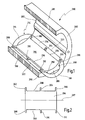
- Fig. 1 is a stator for a series motor according to the invention shown and designated overall with the number 280.
- the stator 280 is in cut in half. It can also be composed of two halves be, as is known from DE 195 07 264 A1. After that the assembly of the winding packages on the stator is simplified, since only after the winding packages have been assembled Halves are joined together by pins provided in axial openings are inserted and then the resulting magnetically closed yoke 281 by upsetting the pins are fixed.
- stator 280 Regardless of whether the stator 280 consists of two axial halves is composed or formed in one piece, forms the Stator 280 the closed yoke 281 and has two field poles on which field windings are fitted.
- Fig. 1 is only to recognize a field pole 284 and the associated field coil 214.
- Field pole 284 has a central portion 285 that is part of the closed yoke 281. From the central From section 285, two pole horns 286, 290 extend to the sides approximately in the circumferential direction. In doing so, they define axial grooves 288 and 292 between the pole horns 286, 290 and the closed yoke 281.
- the field coil 214 is designed as a molded coil that is external is wrapped and usually by wrapping with a suitable Band joined to a fixed winding package which can then be mounted on the stator.
- the Field coil 214 has two axial ends 316, 313 and two longitudinal sections 320, 322 that extend between them.
- the Field coil 214 is attached to stator 280 by the longitudinal sections 320, 322 inserted into the axial grooves 288, 292 become.
- the longitudinal sections 320, 322 as in the state known in the art, usually with a suitable insulating paper struck (not shown).
- the axial ends 316, 318 then stand over the axial ends 282, 283 of the stator 280 and are around the stator ends according to FIG. 1 bent down.
- each Projections 302, 304, 306 and 308, 310, 312 are provided on each axial edge 294, 296 in the the relevant pole horn 286, 290 ends in the circumferential direction.
- This Projections 302, 304, 306, 308, 310, 312 are designed like tongues, which differ from the relevant axial edges 294 or 296 extend approximately in the circumferential direction.
- Each Polhorn 286, 290 has two protrusions 302, 306 and 308, 312, respectively, on the axial ends 282, 283 of the stator 280 are formed. Further is in the middle between the end projections 302, 306 and 308, 312 each have a further projection 304 or 310 provided.
- the longitudinal sections can 320 or 322 of the winding package over the axial Edges 294 and 296 of the pole horns 286 and 290 laterally protrude and become safe from the protrusions 302 to 312 fixed.
- the protrusions 302 to 312 must thereby do not extend over the entire width of the winding package, but only protrude to a sufficient extent to ensure a safe To ensure fixation of the winding package.
- the Field pole 284 formed symmetrically, so that the two Polhorns 286 and 290 from a line of symmetry 287 extend symmetrically on both sides.
- the stator 280 is made of stamped sheets manufactured, which are packaged and so to a closed Stator package in the form of the closed yoke 281 be put together. It is possible to use the protrusions 302, 304, 306, 308, 310, 312 in the manufacture of the individual sheets by stamping at the same time.
- the tabs 302, 304, 306, 308, 310, 312 are thus advantageously off a single or multiple layers of stamped sheets and consist, for example, of two sheet metal layers.
- the stator 280 can in principle in series-wound motors (Universal motors) can be used with preferred direction, it is however particularly advantageous if it is with braked motors or used for switchable motors with clockwise / anti-clockwise rotation becomes.
- Universal motors Universal motors
- FIG. 3 is a circuit diagram of the engine generally designated 200 shows.
- An armature with armature winding 212 is in series with brushes 217, 218 and a two-pole switch 222 with the two field windings 214, 216 (the field windings can also be viewed as a single field winding, which in two winding parts is divided).
- the field windings 214, 216 are through an on / off switch 220 with the two poles connected to a voltage source, designated N and L. are.
- Switch 222 is a two-pole switch, one Switching the current direction through the armature winding 212 enables. In this way, the direction of rotation of the armature can be switched become.
- stator 280 can be particularly advantageous also used for a braked series motor be, here on the description of such a circuit is dispensed with, since this is basically from EP 1 128 542 A1 is known, to which express reference is made.
Landscapes
- Engineering & Computer Science (AREA)
- Power Engineering (AREA)
- Iron Core Of Rotating Electric Machines (AREA)
- Dc Machiner (AREA)
Abstract
Description
- Fig. 1
- eine perspektivische Darstellung eines Stators gemäß der Erfindung, der zum Zwecke der einfacheren Darstellung in zwei Hälften geschnitten ist;
- Fig. 2
- eine ebene Projektion des Feldpoles gemäß Fig. 1, von der Innenseite aus gesehen und
- Fig. 3
- ein vereinfachtes Schaltbild eines erfindungsgemäßen Motors mit einem Stator gemäß Fig. 1, bei dem die Drehrichtung umschaltbar ist.
Claims (9)
- Reihenschlußmotor, insbesondere Universalmotor für ein Elektrowerkzeug, mit einem Anker, der eine kommutierende Ankerwicklung (212) aufweist, mit einem Stator (280), der ein magnetisch geschlossenes Joch (281) bildet und in dem der Anker drehbar aufgenommen ist, mit wenigstens zwei Feldpolen (284), die auf dem Stator (280) aufgenommen sind, wobei jeder Feldpol (284) zwei Polhörner (286, 290) aufweist, die durch axiale Kanten (294, 296) in Umfangsrichtung abgeschlossen sind, dadurch gekennzeichnet, daß jedes Polhorn (286, 290) wenigstens zwei über die axialen Kanten (294, 296) hinaus vorstehende Vorsprünge (302, 304, 306, 308, 310, 312) aufweist.
- Reihenschlußmotor nach Anspruch 1, dadurch gekennzeichnet, daß sich die Polhörner (286, 290) jeweils von einem mittleren Abschnitt (285) aus, der Teil des Joches (281) ist, nach außen etwa in Umfangsrichtung unter Bildung von axial verlaufenden Nuten (288, 292) zur Wicklungsaufnahme erstrecken, und daß jeder Feldpol (284) eine Feldspule (214, 216) aufweist, die Längsabschnitte (320, 322) aufweist, die in die Nuten (288, 292) eingelegt und durch die Vorsprünge (302, 304, 306, 308, 310, 312) zumindest teilweise gehalten sind.
- Reihenschlußmotor nach Anspruch 1, dadurch gekennzeichnet, daß die Feldspulen (214, 216) als Formspulen ausgebildet sind, die mit ihren Längsabschnitten (320, 322) in die Nuten (288, 292) eingelegt sind und mit axialen Endabschnitten (316, 318) über die axialen Enden (282, 283) des Stators (280) hinaus vorstehen.
- Reihenschlußmotor nach einem der vorhergehenden Ansprüche, dadurch gekennzeichnet, daß jedes Polhorn (286, 290) mindestens einen weiteren Vorsprung (304, 310) aufweist, der über die axiale Kante (294, 296) hinaus vorsteht.
- Reihenschlußmotor nach einem der vorhergehenden Ansprüche, dadurch gekennzeichnet, daß jedes Polhorn (286, 290) an seinen axialen Enden jeweils einen Vorsprung (302, 306, 308, 312) aufweist.
- Reihenschlußmotor nach einem der vorhergehenden Ansprüche, gekennzeichnet durch Mittel (222) zur Umschaltung der Drehrichtung des Ankers.
- Reihenschlußmotor nach einem der Ansprüche 1 bis 5, dadurch gekennzeichnet, daß der Motor eine bevorzugte Drehrichtung aufweist, und daß eine Einrichtung zum Bremsen des Motors vorgesehen ist.
- Reihenschlußmotor nach einem der vorhergehenden Ansprüche, dadurch gekennzeichnet, daß der Stator (280) aus Stanzblechen zusammengesetzt ist und daß die Vorsprünge (302, 304, 306, 308, 310, 312) an den Polhörnern (286, 290) beim Stanzvorgang hergestellt sind.
- Reihenschlußmotor nach Anspruch 8, dadurch gekennzeichnet, daß die Vorsprünge (302, 304, 306, 308, 310, 312) aus einer oder mehreren Lagen von Stanzblechen zusammengesetzt sind.
Applications Claiming Priority (2)
| Application Number | Priority Date | Filing Date | Title |
|---|---|---|---|
| DE10209010 | 2002-02-26 | ||
| DE2002109010 DE10209010A1 (de) | 2002-02-26 | 2002-02-26 | Reihenschlußmotor |
Publications (3)
| Publication Number | Publication Date |
|---|---|
| EP1339158A2 true EP1339158A2 (de) | 2003-08-27 |
| EP1339158A3 EP1339158A3 (de) | 2006-02-15 |
| EP1339158B1 EP1339158B1 (de) | 2013-10-02 |
Family
ID=27635332
Family Applications (1)
| Application Number | Title | Priority Date | Filing Date |
|---|---|---|---|
| EP20030003468 Expired - Lifetime EP1339158B1 (de) | 2002-02-26 | 2003-02-15 | Reihenschlussmotor |
Country Status (2)
| Country | Link |
|---|---|
| EP (1) | EP1339158B1 (de) |
| DE (1) | DE10209010A1 (de) |
Families Citing this family (5)
| Publication number | Priority date | Publication date | Assignee | Title |
|---|---|---|---|---|
| US7078843B2 (en) | 2003-09-05 | 2006-07-18 | Black & Decker Inc. | Field assemblies and methods of making same |
| US7205696B2 (en) | 2003-09-05 | 2007-04-17 | Black & Decker Inc. | Field assemblies having pole pieces with ends that decrease in width, and methods of making same |
| US7211920B2 (en) | 2003-09-05 | 2007-05-01 | Black & Decker Inc. | Field assemblies having pole pieces with axial lengths less than an axial length of a back iron portion and methods of making same |
| WO2005027306A2 (en) | 2003-09-05 | 2005-03-24 | Black & Decker Inc. | Field assemblies and methods of making same |
| EP2568573A3 (de) | 2005-03-07 | 2014-06-04 | Black & Decker Inc. | Elektrowerkzeug mit einem Motor mit mehrteiligem Ständer |
Family Cites Families (6)
| Publication number | Priority date | Publication date | Assignee | Title |
|---|---|---|---|---|
| DE4038028A1 (de) * | 1990-11-29 | 1992-06-04 | Bosch Gmbh Robert | Polkern |
| DE19507264A1 (de) * | 1995-03-03 | 1996-09-12 | Fein C & E | Ständer für eine elektrische Außenpolmaschine |
| DE19700074A1 (de) * | 1996-03-22 | 1997-09-25 | Hans Hermann Rottmerhusen | Drehrichtungsumkehrbarer Universalmotor |
| JP3440782B2 (ja) * | 1997-10-29 | 2003-08-25 | 三菱電機株式会社 | リラクタンスモータ及び圧縮機駆動用リラクタンスモータ |
| GB2344224A (en) * | 1998-11-30 | 2000-05-31 | Huang Shu Chen | Two part laminated stator of motor |
| EP1128542B1 (de) * | 2000-02-25 | 2010-12-29 | C. & E. Fein GmbH | Gebremster Reihenschlussmotor |
-
2002
- 2002-02-26 DE DE2002109010 patent/DE10209010A1/de not_active Withdrawn
-
2003
- 2003-02-15 EP EP20030003468 patent/EP1339158B1/de not_active Expired - Lifetime
Also Published As
| Publication number | Publication date |
|---|---|
| EP1339158A3 (de) | 2006-02-15 |
| DE10209010A1 (de) | 2003-09-04 |
| EP1339158B1 (de) | 2013-10-02 |
Similar Documents
| Publication | Publication Date | Title |
|---|---|---|
| DE102004058046B4 (de) | Hochpolige permanenterregte Synchronmaschine mit Zahnspulen | |
| DE69812246T2 (de) | Drehende elektrische Maschine mit vom Joch sich radial nach aussen erstreckender Ausbuchtung | |
| DE19507264A1 (de) | Ständer für eine elektrische Außenpolmaschine | |
| DE1613671B2 (de) | Einphasen-asynchronmotor | |
| DE60124825T2 (de) | Erregerwicklung | |
| DE102016211833A1 (de) | Wicklungsträger | |
| DE102011053609A1 (de) | Drehende elektrische Maschine | |
| EP1339158B1 (de) | Reihenschlussmotor | |
| DE1814383A1 (de) | Dynamoelektrische Maschine mit Reluktanzwirkung | |
| EP1997212A1 (de) | Elektrische maschine | |
| EP2929618A2 (de) | Zahnsegment-spulen-kombination für eine elektrische maschine | |
| DE102012218995A1 (de) | Läuferanordnung für eine permanentmagneterregte elektrische Maschine | |
| EP0897212B1 (de) | Reihenschlussmotor | |
| DE69829652T2 (de) | Stator eines Einphasenelektromotors mit vier parallele Achsen aufweisenden Polen | |
| DE4411145B4 (de) | Fahrradnabe mit darin angeordnetem Gleichstromgenerator | |
| DE102015013028A1 (de) | Statorkörper für einen lnnenläufer | |
| DE4101666C2 (de) | ||
| EP0074020B1 (de) | Synchronmaschine | |
| DE102021104785A1 (de) | Läufer für eine Synchronmaschine | |
| DE3511408A1 (de) | Umlaufende dynamoelektrische induktions-verbundmaschine | |
| EP3624310B1 (de) | Stator mit kompakter isolation sowie verfahren zur herstellung eines solchen stators | |
| DE69717703T2 (de) | Magnetmotor | |
| DE102006037758A1 (de) | Statoranordnung für eine elektrische Maschine und Verfahren zum Herstellen der Statoranordnung | |
| WO2022161788A1 (de) | Verfahren und vorrichtung zum herstellen eines stators für einen bürstenloser gleichstrommotor | |
| DE102023117311A1 (de) | Stator einer elektrischen Rotationsmaschine, Statoranordnung und elektrische Rotationsmaschine |
Legal Events
| Date | Code | Title | Description |
|---|---|---|---|
| PUAI | Public reference made under article 153(3) epc to a published international application that has entered the european phase |
Free format text: ORIGINAL CODE: 0009012 |
|
| AK | Designated contracting states |
Designated state(s): AT BE BG CH CY CZ DE DK EE ES FI FR GB GR HU IE IT LI LU MC NL PT SE SI SK TR |
|
| AX | Request for extension of the european patent |
Extension state: AL LT LV MK RO |
|
| RAP1 | Party data changed (applicant data changed or rights of an application transferred) |
Owner name: C. & E. FEIN GMBH |
|
| RAP1 | Party data changed (applicant data changed or rights of an application transferred) |
Owner name: C. & E. FEIN GMBH |
|
| PUAL | Search report despatched |
Free format text: ORIGINAL CODE: 0009013 |
|
| AK | Designated contracting states |
Kind code of ref document: A3 Designated state(s): AT BE BG CH CY CZ DE DK EE ES FI FR GB GR HU IE IT LI LU MC NL PT SE SI SK TR |
|
| AX | Request for extension of the european patent |
Extension state: AL LT LV MK RO |
|
| RAP3 | Party data changed (applicant data changed or rights of an application transferred) |
Owner name: C. & E. FEIN GMBH |
|
| 17P | Request for examination filed |
Effective date: 20060711 |
|
| AKX | Designation fees paid |
Designated state(s): CH DE FR GB IT LI |
|
| 17Q | First examination report despatched |
Effective date: 20070327 |
|
| REG | Reference to a national code |
Ref country code: DE Ref legal event code: R079 Ref document number: 50314899 Country of ref document: DE Free format text: PREVIOUS MAIN CLASS: H02K0003520000 Ipc: H02K0001140000 |
|
| RIC1 | Information provided on ipc code assigned before grant |
Ipc: H02K 3/52 20060101ALI20130426BHEP Ipc: H02K 1/14 20060101AFI20130426BHEP |
|
| GRAP | Despatch of communication of intention to grant a patent |
Free format text: ORIGINAL CODE: EPIDOSNIGR1 |
|
| INTG | Intention to grant announced |
Effective date: 20130621 |
|
| GRAS | Grant fee paid |
Free format text: ORIGINAL CODE: EPIDOSNIGR3 |
|
| GRAA | (expected) grant |
Free format text: ORIGINAL CODE: 0009210 |
|
| AK | Designated contracting states |
Kind code of ref document: B1 Designated state(s): CH DE FR GB IT LI |
|
| REG | Reference to a national code |
Ref country code: GB Ref legal event code: FG4D Free format text: NOT ENGLISH |
|
| REG | Reference to a national code |
Ref country code: CH Ref legal event code: EP Ref country code: CH Ref legal event code: NV Representative=s name: TROESCH SCHEIDEGGER WERNER AG, CH |
|
| REG | Reference to a national code |
Ref country code: DE Ref legal event code: R096 Ref document number: 50314899 Country of ref document: DE Effective date: 20131128 |
|
| REG | Reference to a national code |
Ref country code: DE Ref legal event code: R097 Ref document number: 50314899 Country of ref document: DE |
|
| PLBE | No opposition filed within time limit |
Free format text: ORIGINAL CODE: 0009261 |
|
| STAA | Information on the status of an ep patent application or granted ep patent |
Free format text: STATUS: NO OPPOSITION FILED WITHIN TIME LIMIT |
|
| 26N | No opposition filed |
Effective date: 20140703 |
|
| REG | Reference to a national code |
Ref country code: DE Ref legal event code: R097 Ref document number: 50314899 Country of ref document: DE Effective date: 20140703 |
|
| REG | Reference to a national code |
Ref country code: FR Ref legal event code: PLFP Year of fee payment: 14 |
|
| PGFP | Annual fee paid to national office [announced via postgrant information from national office to epo] |
Ref country code: IT Payment date: 20160222 Year of fee payment: 14 Ref country code: CH Payment date: 20160211 Year of fee payment: 14 |
|
| PGFP | Annual fee paid to national office [announced via postgrant information from national office to epo] |
Ref country code: FR Payment date: 20160108 Year of fee payment: 14 |
|
| REG | Reference to a national code |
Ref country code: CH Ref legal event code: PL |
|
| PG25 | Lapsed in a contracting state [announced via postgrant information from national office to epo] |
Ref country code: CH Free format text: LAPSE BECAUSE OF NON-PAYMENT OF DUE FEES Effective date: 20170228 Ref country code: LI Free format text: LAPSE BECAUSE OF NON-PAYMENT OF DUE FEES Effective date: 20170228 |
|
| REG | Reference to a national code |
Ref country code: FR Ref legal event code: ST Effective date: 20171031 |
|
| PG25 | Lapsed in a contracting state [announced via postgrant information from national office to epo] |
Ref country code: FR Free format text: LAPSE BECAUSE OF NON-PAYMENT OF DUE FEES Effective date: 20170228 |
|
| PG25 | Lapsed in a contracting state [announced via postgrant information from national office to epo] |
Ref country code: IT Free format text: LAPSE BECAUSE OF NON-PAYMENT OF DUE FEES Effective date: 20170215 |
|
| PGFP | Annual fee paid to national office [announced via postgrant information from national office to epo] |
Ref country code: DE Payment date: 20180130 Year of fee payment: 16 Ref country code: GB Payment date: 20180214 Year of fee payment: 16 |
|
| REG | Reference to a national code |
Ref country code: DE Ref legal event code: R119 Ref document number: 50314899 Country of ref document: DE |
|
| GBPC | Gb: european patent ceased through non-payment of renewal fee |
Effective date: 20190215 |
|
| PG25 | Lapsed in a contracting state [announced via postgrant information from national office to epo] |
Ref country code: GB Free format text: LAPSE BECAUSE OF NON-PAYMENT OF DUE FEES Effective date: 20190215 Ref country code: DE Free format text: LAPSE BECAUSE OF NON-PAYMENT OF DUE FEES Effective date: 20190903 |