EP1338809A1 - Dichtungsvorrichtung für ein Wellenlager - Google Patents
Dichtungsvorrichtung für ein Wellenlager Download PDFInfo
- Publication number
- EP1338809A1 EP1338809A1 EP02100186A EP02100186A EP1338809A1 EP 1338809 A1 EP1338809 A1 EP 1338809A1 EP 02100186 A EP02100186 A EP 02100186A EP 02100186 A EP02100186 A EP 02100186A EP 1338809 A1 EP1338809 A1 EP 1338809A1
- Authority
- EP
- European Patent Office
- Prior art keywords
- intermediate element
- bearing
- shaft
- crankshaft
- wing elements
- Prior art date
- Legal status (The legal status is an assumption and is not a legal conclusion. Google has not performed a legal analysis and makes no representation as to the accuracy of the status listed.)
- Granted
Links
Images

Classifications
-
- F—MECHANICAL ENGINEERING; LIGHTING; HEATING; WEAPONS; BLASTING
- F16—ENGINEERING ELEMENTS AND UNITS; GENERAL MEASURES FOR PRODUCING AND MAINTAINING EFFECTIVE FUNCTIONING OF MACHINES OR INSTALLATIONS; THERMAL INSULATION IN GENERAL
- F16C—SHAFTS; FLEXIBLE SHAFTS; ELEMENTS OR CRANKSHAFT MECHANISMS; ROTARY BODIES OTHER THAN GEARING ELEMENTS; BEARINGS
- F16C3/00—Shafts; Axles; Cranks; Eccentrics
- F16C3/04—Crankshafts, eccentric-shafts; Cranks, eccentrics
- F16C3/06—Crankshafts
- F16C3/14—Features relating to lubrication
-
- F—MECHANICAL ENGINEERING; LIGHTING; HEATING; WEAPONS; BLASTING
- F02—COMBUSTION ENGINES; HOT-GAS OR COMBUSTION-PRODUCT ENGINE PLANTS
- F02F—CYLINDERS, PISTONS OR CASINGS, FOR COMBUSTION ENGINES; ARRANGEMENTS OF SEALINGS IN COMBUSTION ENGINES
- F02F11/00—Arrangements of sealings in combustion engines
- F02F11/007—Arrangements of sealings in combustion engines involving rotary applications
-
- F—MECHANICAL ENGINEERING; LIGHTING; HEATING; WEAPONS; BLASTING
- F16—ENGINEERING ELEMENTS AND UNITS; GENERAL MEASURES FOR PRODUCING AND MAINTAINING EFFECTIVE FUNCTIONING OF MACHINES OR INSTALLATIONS; THERMAL INSULATION IN GENERAL
- F16C—SHAFTS; FLEXIBLE SHAFTS; ELEMENTS OR CRANKSHAFT MECHANISMS; ROTARY BODIES OTHER THAN GEARING ELEMENTS; BEARINGS
- F16C17/00—Sliding-contact bearings for exclusively rotary movement
- F16C17/12—Sliding-contact bearings for exclusively rotary movement characterised by features not related to the direction of the load
- F16C17/24—Sliding-contact bearings for exclusively rotary movement characterised by features not related to the direction of the load with devices affected by abnormal or undesired positions, e.g. for preventing overheating, for safety
-
- F—MECHANICAL ENGINEERING; LIGHTING; HEATING; WEAPONS; BLASTING
- F16—ENGINEERING ELEMENTS AND UNITS; GENERAL MEASURES FOR PRODUCING AND MAINTAINING EFFECTIVE FUNCTIONING OF MACHINES OR INSTALLATIONS; THERMAL INSULATION IN GENERAL
- F16C—SHAFTS; FLEXIBLE SHAFTS; ELEMENTS OR CRANKSHAFT MECHANISMS; ROTARY BODIES OTHER THAN GEARING ELEMENTS; BEARINGS
- F16C33/00—Parts of bearings; Special methods for making bearings or parts thereof
- F16C33/72—Sealings
- F16C33/74—Sealings of sliding-contact bearings
-
- F—MECHANICAL ENGINEERING; LIGHTING; HEATING; WEAPONS; BLASTING
- F16—ENGINEERING ELEMENTS AND UNITS; GENERAL MEASURES FOR PRODUCING AND MAINTAINING EFFECTIVE FUNCTIONING OF MACHINES OR INSTALLATIONS; THERMAL INSULATION IN GENERAL
- F16C—SHAFTS; FLEXIBLE SHAFTS; ELEMENTS OR CRANKSHAFT MECHANISMS; ROTARY BODIES OTHER THAN GEARING ELEMENTS; BEARINGS
- F16C9/00—Bearings for crankshafts or connecting-rods; Attachment of connecting-rods
- F16C9/02—Crankshaft bearings
Definitions
- Shaft bearings are used to rotate a shaft.
- a shaft bearing for the crankshaft of a motor vehicle considered. It is, for example, for the formation of such a shaft bearing known from US Re.32,764, the shaft by means of semi-cylindrical bearing shells to be stored on the crankcase or engine block, whereby one half of the bearing shell has a radial bearing surface and perpendicular to it two axial bearing surfaces have, which the shaft in radial or axial Support direction. The other half of the bearing shell consists of only one half shell.
- the wing elements are the intermediate element inclined towards each other starting from the connecting web. Additionally or alternatively, the wing elements can also increase radial distance from the bearing axis of a shaft bearing into which it installed, become thinner. Both characteristics, the inclination of the wing elements or the change in their thickness correspond to one frequently encountered shaping of bearing shell carriers, which by their manufacture in the (pressure) casting process and the required draft is conditional. In such bearing shell supports, the thrust bearing surfaces are not exactly parallel to each other, but more or less inclined. This inclination leads to a change in the distance between the thrust bearing surfaces of bearing shell and shaft, which by the design described above of the intermediate element is advantageously compensated for.
- the intermediate element has lubricant grooves and / or lubricant pockets for the distribution and storage of lubricants having.
- Such lubricant grooves / pockets can in particular be formed the wing elements.
- the intermediate element can be used in particular dimensioned for mounting the crankshaft of an internal combustion engine and be set up.
- the invention further relates to a shaft bearing containing a bearing shell with a Radial bearing surface and at least one axial bearing surface, which is characterized is that it contains an intermediate element that is adjacent to the thrust bearing surface the bearing shell is arranged.
- Such an intermediate element fills thus a possible empty space between the lower bearing shell support and the Shaft and thereby ensures an even oil distribution on all bearing surfaces for sure.
- the intermediate element can in particular be explained in the above Be kind.
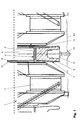
- Figure 1 shows a side view of a section of a crankshaft 1, which serves to move the pistons of an internal combustion engine up and down implement a rotary motion.
- the crankshaft 1 contains in a known manner Way a sequence of crank pins 2 on which connecting rods (not shown) are mounted, and shaft journal 4, on which the crankshaft 1 rotatably mounted is.
- the latter bearing of the crankshaft is carried out using bearing shells 5, one of which is shown schematically in cross section in FIG is.
- the bearing shells 5 are generally semi-cylindrical. You point a radial bearing surface 3 facing the shaft journal 4. Additionally contains the upper bearing shell two perpendicular to the radial bearing surface in axial bearings14 pointing in opposite directions with the resulting ones Axial bearing surfaces 6.
- the crankshaft 1 On the radial bearing surface 3, the crankshaft 1 becomes radial Direction stored by means of an oil film, the lubricating oil through in Engine block extending oil channels is supplied. The oil spreads from the radial end Oil channels is supplied. The oil is distributed from the radial bearing usually on the axial bearing surfaces 6 until it is in the catch basin or Oil drip shield 12 accumulates on the bottom of the crankshaft housing.
- the intermediate element 7 can preferably be made of an inexpensive plastic such as polyamide. It can face each other with its two Wing elements 11 in the space between the bearing shell support 8 and crankshaft 1 are clipped in, which is also the case in Retrofitting can be done when servicing the engine.
- At least one small oil pocket 13 (Figure 2) in the wing elements 11 of the Intermediate element 7 may be integrated, in which oil when the engine is at a standstill is stocked.
- one or more resilient Bars or support members 10 may be arranged, via which the intermediate element 7 on the oil drip plate 12 or other parts in the vicinity supports in order to be held in the intended place in this way.
- the bearing shell support 8 has an axis A of the bearing tapered course, which due to the necessary draft when casting the bearing shell support 8 arises.
- the wing elements 11 of the intermediate element 7 are preferred formed such that they thicken towards axis A. Furthermore, they can be inclined towards one another when viewed in the direction of the axis A.
- the intermediate element 7 ensures centering of the bearing shell carrier 8 between the crank webs of the crankshaft 1. During the first hours of Use of such an intermediate element 7, the oil pockets 13, the also act as centering grooves, ground in, so that the necessary axial play the crankshaft 1 is guaranteed.
Landscapes
- Engineering & Computer Science (AREA)
- General Engineering & Computer Science (AREA)
- Mechanical Engineering (AREA)
- Ocean & Marine Engineering (AREA)
- Chemical & Material Sciences (AREA)
- Combustion & Propulsion (AREA)
- Shafts, Cranks, Connecting Bars, And Related Bearings (AREA)
- Sliding-Contact Bearings (AREA)
Abstract
Description
Claims (9)
- Zwischenelement (7) für ein Wellenlager, wobei das Wellenlager eine Lagerschale (5) mit einer Radiallagerfläche (3) und zwei in entgegengesetzte Richtungen weisenden Axiallagerflächen (6) aufweist,
dadurch gekennzeichnet, daß
es zwei Flügelelemente (11) aufweist, welche jeweils unter einer Axiallagerfläche (6) eines Lagerschalenträgers (8) angeordnet werden können. - Zwischenelement (7) nach Anspruch 1,
dadurch gekennzeichnet, daß
dieses aus einem für die zu lagernde Welle (1) nicht abrasiven Material besteht, insbesondere aus einem Kunststoff. - Zwischenelement (7) nach Anspruch 1 oder 2,
dadurch gekennzeichnet, daß
die Flügelelemente (11) durch einen Verbindungssteg (9) miteinander verbunden sind. - Zwischenelement (7) nach Anspruch 3,
dadurch gekennzeichnet, daß
die Flügelelemente (11) ausgehend vom Verbindungssteg (9) einander zugeneigt sind. - Zwischenelement (7) nach einem der Ansprüche 1 bis 4,
dadurch gekennzeichnet, daß
die Flügelelemente (11) mit zunehmendem radialen Abstand von der Achse (A) eines Wellenlagers dünner werden. - Zwischenelement (7) nach einem der Ansprüche 1 bis 5,
dadurch gekennzeichnet, daß
dieses Abstützglieder (10) enthält, welche es an Gehäuseteilen (12) einer Brennkraftmaschine abstützen können. - Zwischenelement (7) nach einem der Ansprüche 1 bis 6,
dadurch gekennzeichnet, daß
dieses Schmiermitteltaschen (13) und/oder Schmiermittelnuten zur Bevorratung und/oder Verteilung von Schmiermittel aufweist. - Zwischenelement (7) nach einem der Ansprüche 1 bis 7,
dadurch gekennzeichnet, daß
dieses für die Verwendung an der Kurbelwelle (1) einer Brennkraftmaschine dimensioniert und eingerichtet ist. - Wellenlager enthaltend einen Lagerschalenträger (8),
dadurch gekennzeichnet, daß
das dieses ein Zwischenelement (7) nach einem der Ansprüche 1 bis 8 enthält.
Priority Applications (2)
| Application Number | Priority Date | Filing Date | Title |
|---|---|---|---|
| EP20020100186 EP1338809B1 (de) | 2002-02-25 | 2002-02-25 | Dichtungsvorrichtung für ein Wellenlager |
| DE50206556T DE50206556D1 (de) | 2002-02-25 | 2002-02-25 | Dichtungsvorrichtung für ein Wellenlager |
Applications Claiming Priority (1)
| Application Number | Priority Date | Filing Date | Title |
|---|---|---|---|
| EP20020100186 EP1338809B1 (de) | 2002-02-25 | 2002-02-25 | Dichtungsvorrichtung für ein Wellenlager |
Publications (2)
| Publication Number | Publication Date |
|---|---|
| EP1338809A1 true EP1338809A1 (de) | 2003-08-27 |
| EP1338809B1 EP1338809B1 (de) | 2006-04-26 |
Family
ID=27635884
Family Applications (1)
| Application Number | Title | Priority Date | Filing Date |
|---|---|---|---|
| EP20020100186 Expired - Lifetime EP1338809B1 (de) | 2002-02-25 | 2002-02-25 | Dichtungsvorrichtung für ein Wellenlager |
Country Status (2)
| Country | Link |
|---|---|
| EP (1) | EP1338809B1 (de) |
| DE (1) | DE50206556D1 (de) |
Citations (2)
| Publication number | Priority date | Publication date | Assignee | Title |
|---|---|---|---|---|
| BE471392A (de) * | ||||
| FR2674905A1 (fr) * | 1991-04-05 | 1992-10-09 | Renault | Procede de lubrification pour un vilebrequin de moteur a combustion interne et moyens pour la mise en óoeuvre de ce procede. |
-
2002
- 2002-02-25 DE DE50206556T patent/DE50206556D1/de not_active Expired - Lifetime
- 2002-02-25 EP EP20020100186 patent/EP1338809B1/de not_active Expired - Lifetime
Patent Citations (2)
| Publication number | Priority date | Publication date | Assignee | Title |
|---|---|---|---|---|
| BE471392A (de) * | ||||
| FR2674905A1 (fr) * | 1991-04-05 | 1992-10-09 | Renault | Procede de lubrification pour un vilebrequin de moteur a combustion interne et moyens pour la mise en óoeuvre de ce procede. |
Also Published As
| Publication number | Publication date |
|---|---|
| EP1338809B1 (de) | 2006-04-26 |
| DE50206556D1 (de) | 2006-06-01 |
Similar Documents
| Publication | Publication Date | Title |
|---|---|---|
| DE102005009470B4 (de) | Gleitlager | |
| DE102007027869B4 (de) | Turbolader mit einem Turboladergehäuse | |
| DE102005011372B4 (de) | Gleitlager | |
| DE102014213994B4 (de) | Käfig für ein Rollenlager und Rollenlager | |
| EP0753678B1 (de) | Gleitlager für eine Welle | |
| DE102011104002A1 (de) | Lagerhalbschale | |
| DE3817312A1 (de) | Schraubenverdichter | |
| DE102008063760A1 (de) | Pleuelstangenlager für Verbrennungsmotoren | |
| DE102010022512A1 (de) | Gleitlager für Verbrennungsmotor | |
| DE102009052793A1 (de) | Gleitlager für Verbrennungsmotor und Gleitlagervorrichtung | |
| DE102010036284A1 (de) | Lager für eine Pleuelstange eines Verbrennungsmotors | |
| EP0983438B1 (de) | Radialkolbenpumpe zur kraftstoffhochdruckversorgung | |
| DE102010008239A1 (de) | Pleuelstangenlager in einem Verbrennungsmotor | |
| EP0757186A2 (de) | Gleitlager-Gleitschuh mit einer Druckfeder | |
| DE102013100845B4 (de) | Kraftstoff-Zuführpumpe | |
| DE4125730C2 (de) | Rollenlager mit durch Verformen gebildeten Rollenhalterungsvorsprüngen | |
| DE19947462C1 (de) | Sintergleitlager für Motoren und Getriebe | |
| DE60213972T2 (de) | Betriebsfertiges lager mit schmieröffnungen | |
| EP0803606A2 (de) | Durchbiegungsausgleichswalze | |
| DE102009055152A1 (de) | Geteiltes Gleitlager für eine Kurbelwelle in einem Verbrennungsmotor und geteilte Lagervorrichtung | |
| DE2631376C2 (de) | Kreuzkopfzapfenlager für Kolbenmaschinen, insbesondere für Dieselbrennkraftm aschinen | |
| DE102005030307A1 (de) | Lagerschale, halbkreisförmige Lagerschalenhälfte, Verwendung von Lagerschalenhälften und Kurbelwellenhauptlager | |
| DE102016005644A1 (de) | Lagereinrichtung zum axialen Lagern einer Kurbelwelle einer Hubkolbenmaschine | |
| EP1338809B1 (de) | Dichtungsvorrichtung für ein Wellenlager | |
| DE102023116056A1 (de) | Kurbelwelle |
Legal Events
| Date | Code | Title | Description |
|---|---|---|---|
| PUAI | Public reference made under article 153(3) epc to a published international application that has entered the european phase |
Free format text: ORIGINAL CODE: 0009012 |
|
| AK | Designated contracting states |
Designated state(s): AT BE CH CY DE DK ES FI FR GB GR IE IT LI LU MC NL PT SE TR |
|
| AX | Request for extension of the european patent |
Extension state: AL LT LV MK RO SI |
|
| 17P | Request for examination filed |
Effective date: 20040227 |
|
| AKX | Designation fees paid |
Designated state(s): DE FR GB |
|
| GRAP | Despatch of communication of intention to grant a patent |
Free format text: ORIGINAL CODE: EPIDOSNIGR1 |
|
| RAP1 | Party data changed (applicant data changed or rights of an application transferred) |
Owner name: FORD GLOBAL TECHNOLOGIES, LLC |
|
| GRAS | Grant fee paid |
Free format text: ORIGINAL CODE: EPIDOSNIGR3 |
|
| GRAA | (expected) grant |
Free format text: ORIGINAL CODE: 0009210 |
|
| AK | Designated contracting states |
Kind code of ref document: B1 Designated state(s): DE FR GB |
|
| REG | Reference to a national code |
Ref country code: GB Ref legal event code: FG4D Free format text: NOT ENGLISH |
|
| RAP2 | Party data changed (patent owner data changed or rights of a patent transferred) |
Owner name: FORD GLOBAL TECHNOLOGIES, LLC. |
|
| REF | Corresponds to: |
Ref document number: 50206556 Country of ref document: DE Date of ref document: 20060601 Kind code of ref document: P |
|
| GBT | Gb: translation of ep patent filed (gb section 77(6)(a)/1977) |
Effective date: 20060801 |
|
| ET | Fr: translation filed | ||
| PLBE | No opposition filed within time limit |
Free format text: ORIGINAL CODE: 0009261 |
|
| STAA | Information on the status of an ep patent application or granted ep patent |
Free format text: STATUS: NO OPPOSITION FILED WITHIN TIME LIMIT |
|
| 26N | No opposition filed |
Effective date: 20070129 |
|
| REG | Reference to a national code |
Ref country code: FR Ref legal event code: PLFP Year of fee payment: 14 |
|
| PGFP | Annual fee paid to national office [announced via postgrant information from national office to epo] |
Ref country code: DE Payment date: 20150227 Year of fee payment: 14 |
|
| PGFP | Annual fee paid to national office [announced via postgrant information from national office to epo] |
Ref country code: FR Payment date: 20150126 Year of fee payment: 14 Ref country code: GB Payment date: 20150126 Year of fee payment: 14 |
|
| REG | Reference to a national code |
Ref country code: DE Ref legal event code: R119 Ref document number: 50206556 Country of ref document: DE |
|
| GBPC | Gb: european patent ceased through non-payment of renewal fee |
Effective date: 20160225 |
|
| REG | Reference to a national code |
Ref country code: FR Ref legal event code: ST Effective date: 20161028 |
|
| PG25 | Lapsed in a contracting state [announced via postgrant information from national office to epo] |
Ref country code: FR Free format text: LAPSE BECAUSE OF NON-PAYMENT OF DUE FEES Effective date: 20160229 Ref country code: GB Free format text: LAPSE BECAUSE OF NON-PAYMENT OF DUE FEES Effective date: 20160225 Ref country code: DE Free format text: LAPSE BECAUSE OF NON-PAYMENT OF DUE FEES Effective date: 20160901 |