EP1338739A2 - Scharnier - Google Patents
Scharnier Download PDFInfo
- Publication number
- EP1338739A2 EP1338739A2 EP03003891A EP03003891A EP1338739A2 EP 1338739 A2 EP1338739 A2 EP 1338739A2 EP 03003891 A EP03003891 A EP 03003891A EP 03003891 A EP03003891 A EP 03003891A EP 1338739 A2 EP1338739 A2 EP 1338739A2
- Authority
- EP
- European Patent Office
- Prior art keywords
- hinge
- bracket
- pin
- lever
- casement
- Prior art date
- Legal status (The legal status is an assumption and is not a legal conclusion. Google has not performed a legal analysis and makes no representation as to the accuracy of the status listed.)
- Withdrawn
Links
Images


Classifications
-
- E—FIXED CONSTRUCTIONS
- E05—LOCKS; KEYS; WINDOW OR DOOR FITTINGS; SAFES
- E05D—HINGES OR SUSPENSION DEVICES FOR DOORS, WINDOWS OR WINGS
- E05D7/00—Hinges or pivots of special construction
- E05D7/04—Hinges adjustable relative to the wing or the frame
- E05D7/0415—Hinges adjustable relative to the wing or the frame with adjusting drive means
- E05D7/0423—Screw-and-nut mechanisms
-
- E—FIXED CONSTRUCTIONS
- E05—LOCKS; KEYS; WINDOW OR DOOR FITTINGS; SAFES
- E05D—HINGES OR SUSPENSION DEVICES FOR DOORS, WINDOWS OR WINGS
- E05D3/00—Hinges with pins
- E05D3/06—Hinges with pins with two or more pins
- E05D3/12—Hinges with pins with two or more pins with two parallel pins and one arm
-
- E—FIXED CONSTRUCTIONS
- E05—LOCKS; KEYS; WINDOW OR DOOR FITTINGS; SAFES
- E05D—HINGES OR SUSPENSION DEVICES FOR DOORS, WINDOWS OR WINGS
- E05D5/00—Construction of single parts, e.g. the parts for attachment
- E05D5/02—Parts for attachment, e.g. flaps
- E05D5/06—Bent flaps
-
- E—FIXED CONSTRUCTIONS
- E05—LOCKS; KEYS; WINDOW OR DOOR FITTINGS; SAFES
- E05Y—INDEXING SCHEME ASSOCIATED WITH SUBCLASSES E05D AND E05F, RELATING TO CONSTRUCTION ELEMENTS, ELECTRIC CONTROL, POWER SUPPLY, POWER SIGNAL OR TRANSMISSION, USER INTERFACES, MOUNTING OR COUPLING, DETAILS, ACCESSORIES, AUXILIARY OPERATIONS NOT OTHERWISE PROVIDED FOR, APPLICATION THEREOF
- E05Y2600/00—Mounting or coupling arrangements for elements provided for in this subclass
- E05Y2600/40—Mounting location; Visibility of the elements
- E05Y2600/41—Concealed
-
- E—FIXED CONSTRUCTIONS
- E05—LOCKS; KEYS; WINDOW OR DOOR FITTINGS; SAFES
- E05Y—INDEXING SCHEME ASSOCIATED WITH SUBCLASSES E05D AND E05F, RELATING TO CONSTRUCTION ELEMENTS, ELECTRIC CONTROL, POWER SUPPLY, POWER SIGNAL OR TRANSMISSION, USER INTERFACES, MOUNTING OR COUPLING, DETAILS, ACCESSORIES, AUXILIARY OPERATIONS NOT OTHERWISE PROVIDED FOR, APPLICATION THEREOF
- E05Y2900/00—Application of doors, windows, wings or fittings thereof
- E05Y2900/10—Application of doors, windows, wings or fittings thereof for buildings or parts thereof
- E05Y2900/13—Type of wing
- E05Y2900/132—Doors
-
- E—FIXED CONSTRUCTIONS
- E05—LOCKS; KEYS; WINDOW OR DOOR FITTINGS; SAFES
- E05Y—INDEXING SCHEME ASSOCIATED WITH SUBCLASSES E05D AND E05F, RELATING TO CONSTRUCTION ELEMENTS, ELECTRIC CONTROL, POWER SUPPLY, POWER SIGNAL OR TRANSMISSION, USER INTERFACES, MOUNTING OR COUPLING, DETAILS, ACCESSORIES, AUXILIARY OPERATIONS NOT OTHERWISE PROVIDED FOR, APPLICATION THEREOF
- E05Y2900/00—Application of doors, windows, wings or fittings thereof
- E05Y2900/10—Application of doors, windows, wings or fittings thereof for buildings or parts thereof
- E05Y2900/13—Type of wing
- E05Y2900/148—Windows
Definitions
- the invention relates to a hinge with two forming a common hinge axis Hinge parts, one on a fixed frame and the other on one Sash frame can be attached.
- hinges for windows and doors for rotatably connecting them to one Frames a frame profile part or a kind of frame are already many design variants known.
- a hinge of the aforementioned type is not the subject of Pre-published patent DE 100 50 796 C1. With this hinge, the frame and the sash frame arranged around rubber or plastic seals. These seals are subject to shear when the window or door is closed, which will reduce their lifespan if they are not regularly lubricated be treated.
- a hinge of the type mentioned is also by the utility model DE 19 79 532 U known.
- This known hinge points to one of the hinge parts a pin aligned parallel to the hinge axis.
- this is a hinge part not adjustable on this pin, but the pin serves as a pivot axis for another Sash.
- This hinge is intended for composite windows where one Floor frame is present, which carries two casement frames. These casements are indeed in the closed state over two seals arranged around each other, however the two casements are rarely opened, namely when the glass panes need to be cleaned.
- the seals are when the two casement is closed not stressed on shear, but only on pressure, but it does anyway just gasket to gasket what is between frame and window or door will never be the case.
- this well-known hinge is different from the one at the beginning called hinge, in so far as it is different when it is closed Window is not completely invisible.
- the trend is moving with modern windows and doors but to make the hinges as invisible as possible. This usually means that the existing seals are mainly sheared during the closing process stressed and often crushed.
- the object of the invention is to design a hinge of the type mentioned in the introduction, that seals provided between the fixed frame and the casement stressed as little as possible during the opening and closing of the casement or get damaged.
- a hinge of the type mentioned solved that at least one of the hinge parts on an axially parallel to Hinge axis aligned pin pivotable and longitudinally guided bracket has that a biasing device the bracket in its longitudinal direction with a Preload force acts on the bracket when it opens when the casement is in contact the pin is pushed, and that the bracket one by closing the casement actuatable locking lever is assigned to the when closing the casement against the biasing force, the bracket moves away from its contact with the pin.
- the hinge according to the invention causes that during the closing movement of the casement neither its seal with the frame nor the seal of the frame with the Sash is in contact. Rather, in the last phase of the closing movement of the Sash this pulled against the frame and thereby its seal as well as the seal of the frame only under pressure.
- This pulling process begins when the locking lever the bracket against the biasing force of the biasing device its abutment on the pin and thus in the direction of the biasing device.
- the extent of the longitudinal displaceability permitted for the bracket the extent of the compressive stress on the seals can be selected. The Seals are therefore minimally endangered by the closing process and have one correspondingly long lifespan.
- the pin engages in an elongated hole in the A bracket, and the bracket is displaceable in the longitudinal direction relative to the pin.
- the pretensioning device has at least one leaf spring.
- a leaf spring instead of a leaf spring, a leaf spring package can also be used be provided.
- One or more leaf springs are useful as a biasing device, because they are between the fixed frame and the one hinge part or between the sash and the other hinge part, depending on whether the one with the pin, the bracket and the locking lever provided a hinge part on the fixed frame or attached to the sash, take up little space.
- the locking lever is on the hinge axis is articulated and has a hook-shaped free end, wherein a clear width measured between the free end and the hinge axis is smaller as an existing between the pin and the hinge axis when the casement is open Distance so that the free end grips the pin when the casement is closed and moves the bracket against the biasing force by the distance between the pin and to reduce the hinge axis.
- the locking lever detects the pin on the closing of the casement the bracket is guided longitudinally to the distance between the hinge axis and to reduce the size of the pin so that the wing can be connected to the fixed frame is tightened.
- the free end of the Locking lever is provided with a limited pivotable tab, which at the Closing the casement from a position in which it grips the pin and with the bracket forms a bent toggle lever, is moved into an end position in which the toggle lever is stretched and the tab is parallel to the bracket.
- the locking lever and the bracket together form a toggle lever, by stretching it initiates the movement that the sash in the last Phase of the closing process and which ensures that the seals in this Phase can only be subjected to pressure.
- the hinge is the closing lever even a toggle lever, which at one end to a stationary part of the one hinge part and is hinged at its other end to the bracket and which is arranged so that it is kinked by the pretensioning force when the casement is open and that it is stretched by closing the sash to the bracket against the biasing force move and reduce the distance between the pin and the hinge axis.
- the hinge is particularly simple and functional construction because one of the hinge parts including the locking lever and the biasing device forms one unit with one or the other hinge part.
- the fixed frame or the sash on which the remaining hinge part is attached only needs to press against the bent knee lever in order to do this to stretch and thus cause the longitudinal displacement of the bracket through which the wing frame is pulled to the fixed frame.
- it is necessary both provide an elongated hole in the bracket so that it can be moved longitudinally is to provide, as well as an elongated hole in one hinge part, so that on this Hinge part articulated toggle lever can be stretched to accommodate the longitudinal displacement of the To effect bracket.
- the bracket is over a Adjustment means in an adjustable horizontal position held in a pivoting position.
- a two-dimensional adjustment of the bracket can take place in a horizontal plane, namely an adjustment on the one hand by longitudinally displacing the bracket transversely to the Pin, in a direction essentially in the longitudinal direction of the bracket, and on the other hand by pivoting the bracket about the axis of the pin.
- the bracket has two lever arms pointing in opposite directions, one lever arm for Hinge axis leads and the adjustment lever is assigned to the other lever arm.
- a structurally simple embodiment provides that the adjusting means is transverse to one another the pin is formed in a threaded bore on the screw engaging a lever arm is. In this way, an adjustment can be made very simply by the bracket around one is rotated correspondingly small angle relative to the pin. It also becomes the Hinge axis adjusted to the appropriate extent in the horizontal direction. Because of the engagement A screw inserted in a threaded hole not only forms the adjusting device, but also acts as a locking device due to its self-locking.
- the hinge adjustment means there are also favorable solutions for the arrangement of the hinge adjustment means.
- the advantageous features according to which the clear width of the interior of the mounting part the length of the threaded Adjustment range corresponds to the screw and thus the screw in the axial direction is held immovably, the mounting part having a front opening for access an internal tool attack of the screw.
- the screw that forms the adjusting means is thus kept immovable in its axial direction and can be rotated by engaging in the bracket this or the relevant lever arm in the mounting part adjust.
- hinge according to the invention that is to the hinge axis bent lever arm of the bracket bent towards the hinge axis educated.
- This configuration of the hinge according to the invention allows additional Measures can be carried out more easily, for example in order to enlarge it To reach the opening angle of a window or a door.
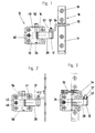
- a first exemplary embodiment of a hinge 10 shown in FIGS. 1-6 has two a common hinge axis 12 forming hinge parts 14 and 16, one of which attachable to a fixed frame 18 and the other to a casement 20 is.
- the hinge 10 can be used in the same way for windows or doors become. Use in fixed frames 18 formed from hollow profiles is advantageous and casement 20. Hinges of this type can also be used in wooden frames or made of other materials. It is also indifferent whether this framework is made Plastic (possibly with a reinforcement made of metal profiles) or made of metal.
- the hinge 10 is designed so that it is in the closed state of the Window or door is invisible. Further is in all of the exemplary embodiments described here the hinge is formed so that one attached to the fixed frame 18 Seal 22 and a seal 24 attached to the sash 20 in the Opening and closing the sash frame as little stress as possible and in particular as little as possible little shear stress. At least one of the hinge parts, and although the hinge part 14 arranged on the fixed frame 18 is advantageous as pivotable on a pin 26 aligned parallel to a hinge axis 12 and longitudinally displaceably guided bracket 28, the bracket 28 via a (in Fig. 6) a total of 29 designated adjustment means held adjustable in a horizontal plane and can be fixed in the set position.
- the bracket 28 carries the hinge axis 12 forming hinge pin 12 'and has an elongated hole 30, which is longitudinally displaceable of the bracket 32 allows.
- the bracket 28 has two of the elongated hole 30 in opposite directions extending lever arms 32 and 34.
- the lever arm 32 leads to the hinge axis 12, and the lever arm 34 is associated with the adjusting means 29.
- the adjusting means 29 has one transverse to the longitudinal direction of the bracket 28 in a threaded bore 36 on the lever arm 34 engaging screw 38.
- the screw 38 is equipped with an internal attack 40, so that this screw rotates through an opening 42 in a mounting part 44 can be.
- the lever arm 32 of the bracket 28 projecting towards the hinge axis 12 is in the direction of the hinge axis 12 formed bent. Furthermore, it is free from the mounting part 44 Cantilever lever arm 32 of the bracket 28 in the direction of the hinge axis 12 at an acute angle bent towards a bearing eye 31.
- the pin 26, at least the lever arm 34 of the bracket 28 and the screw 38 are in the Mounting part 44 arranged, which on the fixed frame 18 or in construction different design of the hinge 10 on the casement 20 of a window or one Door is mountable.
- the mounting part 44 each mounted on the fixed frame 18 by means of fastening screws 43. Therefore the hinge part 14 has mounting holes 41.
- the mounting part 44 is a plate-shaped part having a between an upper wall 48th and a lower wall 50 formed passage 51 for receiving the bracket 28.
- the passage 51 has an opening on its narrow side facing the casement 20 46, from which the lever arm 32 of the bracket 28 protrudes.
- the pin 26 is in the top Wall 48 and in the lower wall 50 of the mounting member 44 transverse to the longitudinal direction of the bracket 28 attached. From the top wall 48, the pin 26 is a little way up and carries a roller 52 (or a cylindrical fitting or the like) for attacking one Closing lever 54 described below.
- the pin 26 is in bores 56 and 58 the upper wall 48 and the lower wall 50 fit tightly.
- opening 46 1 - 3 to the left of of opening 46 are upper wall 48 and lower wall 50 through a front wall 60 connected to each other.
- the opening 42 is arranged, via which the inner attack 40 of the screw 38 is accessible, which in the threaded bore 36 in the Lever arm 34 of the bracket 28 is screwed.
- the mounting part 44 Within the mounting part 44 is the height of the passage 51, that is the distance between the upper wall 48 and the lower wall 50 so dimensioned that the bracket 28 in the Passage 51 is freely displaceable in its longitudinal direction.
- the pin 26 extends between the upper wall 48 and the lower wall 50 of the mounting part 44 through the elongated hole 30 in the bracket 28.
- the length of the elongated hole 30 determines how far the bracket 28 is longitudinally displaceable.
- the length of the slot 30 makes it possible to choose how strong the Seals 22 and 24 are compressed when the casement 20 is closed. The will become clearer below.
- a leaf spring 62 is arranged between the fixed frame 18 and the bracket 28 as a biasing device for the bracket.
- the leaf spring 62 is omitted in FIGS. 1-3 and shown in FIGS. 4-6 only in a view from above. A full view of the Leaf spring 62 can be found in FIGS. 11, 13 and 14.
- the leaf spring 62 acts on the bracket 28 in the longitudinal direction so with a biasing force that the bracket when opening the Sash 20 is urged within the slot 30 in contact with the pin 26.
- the Bracket 28 carries the hinge pin at its end opposite the leaf spring 62 12 'which is parallel to the pin 26.
- the locking lever 54 is part of the other hinge part 16. It is on a tab 17 the other hinge part 16 welded. The tab 17 has mounting holes 19 for Fastening screws 21 for fastening the other hinge part 16 to the casement 20.
- the closing lever 54 is actuated by closing the casement 20. The closing lever 54 counteracts the bracket 28 when the casement 20 closes the biasing force of the leaf spring 62 moves away from its abutment on the pin 26, 1 - 3 moved to the left.
- the locking lever 54 is a U-shaped part that has an end 57 on the hinge axis 12 is articulated. Its hook-shaped free end 55 is used to grasp the Pin 26.
- a clear between the free end 55 and the hinge axis 12 measured Width 64 (indicated in FIG. 5) is smaller than one between when the casement 20 is open the distance between the pin 26 and the hinge axis 12 (shown in FIG. 4).
- the free end 55 detects the pin 26 (more precisely, when the casement 20 closes) the roller 52) mounted on this and moves the bracket 28 against the biasing force the leaf spring 62 to the left by the distance 66 between the pin 26 and the hinge axis 12 downsize.
- FIGS. 1-3 This process is shown in FIGS. 1-3 as well as in FIGS. 4-6 in three phases.
- the sash 20 is almost open.
- the bracket 28 is through the leaf spring 62 pushed to the right into contact with the left edge of slot 30.
- the distance 66 has its maximum value. This is chosen so that the seal 24 without shear stress can be moved past the frame 18, as can readily be seen in FIG. 4 is.
- the free end 55 of the Locking lever 54 against the biasing force of the leaf spring 62 behind the pin 26 and pulls the bracket 28 to the left, the distance 66 being reduced and the seal 24 against the fixed frame 18 is pressed, as can be seen in Fig. 5.
- a second embodiment of a hinge 10 ' is shown, the differs from the exemplary embodiment according to FIGS. 1-6 mainly in that that the cranked free end 55 of the locking lever 54 is at a greater distance from the hinge axis Has 12 and is provided with a limited pivotable tab 68.
- the tab 68 is from a position in which it holds the pin 26 detected and in which the locking lever 54 with the bracket 28 (more precisely with its lever arm 32) forms a bent toggle lever, moved into an end position (shown in FIG. 10), in which the toggle lever is stretched and the tab 68 is parallel to the bracket 28.
- the distance 66 between the hinge axis 12 and the pin 26 at the Closing the sash 20 is reduced to the left against the frame 18 pull and the seals 22 and 24 essentially only to stress.
- the toggle lever in FIG. 10 has been moved into a final locking position by stretching, which he easily maintains until the wing 20 and thus the hinge 10 'is opened again.
- the toggle is arranged in the hinge 10 'according to FIGS. 7-10 so that it can be opened by opening the casement 20 is kinked (shown in FIGS.
- the hinge 10 has the same structure as in the first embodiment according to FIGS. 1-6 and therefore does not need to be repeated here to be described.
- a third embodiment of a hinge 10 " is shown at which the locking lever itself is designed as a toggle lever 78.
- the hinge is 10 ' the tab 68 hinged to the free end 55 by a pin 70 and thus part of the Closing lever 54.
- the pin 26 forms it Toggle joint, while the lever arm 32 of the bracket 28 is the other link of the toggle lever forms.
- the sash 20 is opened wide enough, e.g. 7 is the tab 68 moved away from the pin 26 and the knee lever thus interrupted in the knee joint.
- the two links 80, 82 when opening the casement 20 in the area their toggle joint cannot be separated.
- the links 80, 82 of the toggle lever 78 are connected to each other by a hinge pin 84 forming the toggle joint.
- the Toggle 78 is at one end 86 on a stationary part (here the upper wall 48 of the mounting part 44 ") of one hinge part 14 and 88 at its other end the bracket 28 is pivoted via pivot 90 and 92 and arranged so that it is open Wing frame 20 is kinked by the biasing force of the leaf spring 62 and that it is stretched by closing the sash 20 to the bracket 28 against the biasing force the leaf spring 62 to move and the distance between the pin 26 and the Reduce hinge axis 12.
- the pivot 92 is fixed to the bracket 28.
- the bracket 28 is provided with a bore 94 into which the pivot 92 is tightly fitted.
- the top wall 48 and bottom wall 50 of the mounting member 44 “are each provided with an elongated hole 96 extending in the longitudinal direction of the wall, so that the pivot 92 can undergo a longitudinal displacement of the bracket 28.
- the pivot 90, on which the toggle lever 78 is articulated at one end 86, is in a bore firmly fitted in the upper wall 48.
- the pin 26 is like the other embodiments each in a hole in the upper wall 48 and in the lower wall 50 firmly fitted. Within the bracket 28, the pin 26 penetrates the slot 30.
- a sealing element 98 is attached to the lever arm 32, the when the hinge 10 "is closed, a seal between the two hinge parts 14 and 16 causes.
- the other hinge part 16 has a stop 100, which when closing of the sash 20 presses against the bent knee lever 78 and stretches it.
- the hinge 10 is the front wall 60 that in the other embodiments the upper wall 48 and the lower wall 50 interconnect, not present. This front wall is not necessary with the hinge 10 "because the bracket 28 by means of the pin 26 and the pivot pin 90 is guided in the elongated holes 30 and 96, respectively.
- the structure of the hinge 10 correlates to the structure of the hinges 10 and 10 'and need not be described again here.
- the type and arrangement of the hinge parts 14 or 16 at the upper or lower edge area of a casement 20 can have a wide variety of solutions. It works always about the optimal attachment of the hinge parts to the sash 20 and one simple possibility to bring the hinge part 16 into alignment with the hinge axis 12 and to connect with the hinge part 14.
Landscapes
- Engineering & Computer Science (AREA)
- Mechanical Engineering (AREA)
- Hinges (AREA)
Abstract
Description
- Fig. 1
- ein erstes Ausführungsbeispiel des Scharniers nach der Erfindung in vollständig geöffnetem Zustand, wobei weder ein feststehender Rahmen noch ein Flügelrahmen, an denen die Scharnierteile befestigt sind, dargestellt ist,
- Fig. 2
- das Scharnier nach Fig. 1 in halb geschlossenem Zustand,
- Fig. 3
- das Scharnier nach Fig. 1 in geschlossenem Zustand,
- die Fig. 4 - 6
- das Scharnier nach den Fig. 1 - 3 in drei Phasen des Schließvorganges, wobei zusätzlich auch ein feststehender Rahmen und ein Flügelrahmen gezeigt sind und wobei Fig. 4 das Scharnier in fast geöffnetem Zustand, Fig. 5 das Scharnier in fast geschlossenem Zustand und Fig. 6 das Scharnier in geschlossenem Zustand zeigt (die Darstellungen entsprechen dabei in etwa Ansichten von oben in den Fig. 1 - 3, bei zusätzlich geschnittener Darstellung der unterhalb eines Schließhebels befindlichen Teile des Scharniers),
- die Fig. 7 - 10
- ein zweites Ausführungsbeispiel des Scharniers nach der Erfindung, das in vier verschiedenen Stellungen während des Schließens gezeigt ist, wobei Fig. 10 den vollständig geschlossenen Zustand zeigt, und
- die Fig. 11 - 14
- ein drittes Ausführungsbeispiel des Scharniers nach der Erfindung, wobei wie in den Fig. 1 - 3 wiederum ein feststehender Rahmen und ein Flügelrahmen nicht dargestellt sind.
Claims (15)
- Scharnier mit zwei eine gemeinsame Scharnierachse bildenden Scharnierteilen, von denen eines an einem feststehenden Rahmen und das andere an einem Flügelrahmen befestigbar ist, dadurch gekennzeichnet, dass wenigstens eines (14) der Scharnierteile (14, 16) einen an einem achsparallel zur Scharnierachse (12) ausgerichteten Stift (26) verschwenkbar und längsverschiebbar geführten Bügel (28) aufweist,
dass eine Vorspanneinrichtung (62) den Bügel (28) in dessen Längsrichtung so mit einer Vorspannkraft beaufschlagt, dass der Bügel (28) bei dem Öffnen des Flügelrahmens (20) in Anlage an den Stift (26) gedrängt wird, und
dass dem Bügel (28) ein durch das Schließen des Flügelrahmens (20) betätigbarer Schließhebel (54) zugeordnet ist, der bei dem Schließen des Flügelrahmens (20) den Bügel (28) entgegen der Vorspannkraft von seiner Anlage an dem Stift (26) wegbewegt. - Scharnier nach Anspruch 1, dadurch gekennzeichnet, dass der Stift (26) in ein Langloch (30) des Bügels (28) eingreift und dass der Bügel (28) in Längsrichtung relativ zu dem Stift (26) verschiebbar ist.
- Scharnier nach Anspruch 1 oder 2, dadurch gekennzeichnet, dass die Vorspanneinrichtung (62) wenigstens eine Blattfeder (62) aufweist.
- Scharnier nach einem der Ansprüche 1 bis 3, dadurch gekennzeichnet, dass der Schließhebel (54) an der Scharnierachse (12) angelenkt ist und ein hakenförmig ausgebildetes freies Ende (55) hat,
wobei eine zwischen dem freien Ende (55) und der Scharnierachse (12) gemessene lichte Weite (64) kleiner ist als ein bei geöffnetem Flügelrahmen (20) zwischen dem Stift (26) und der Scharnierachse (12) vorhandener Abstand (66), so dass das freie Ende (55) bei dem Schließen des Flügelrahmens (20) den Stift (26) erfasst und den Bügel (28) entgegen der Vorspannkraft verschiebt, um den Abstand (66) zwischen dem Stift (26) und der Scharnierachse (12) zu verkleinern. - Scharnier nach Anspruch 4, dadurch gekennzeichnet, dass das freie Ende des Schließhebels (54) mit einer begrenzt schwenkbeweglichen Lasche (68) versehen ist, die bei dem Schließen des Flügelrahmens (20) aus einer Lage, in der sie den Stift (26) erfasst und mit dem Bügel (28) einen abgeknickten Kniehebel bildet, in eine Endlage bewegt wird, in der der Kniehebel gestreckt und die Lasche (68) zu dem Bügel (28) parallel ist.
- Scharnier nach einem der Ansprüche 1 bis 3, dadurch gekennzeichnet, dass der Schließhebel selbst ein Kniehebel (78) ist, der an seinem einen Ende (86) an einem stationären Teil des einen Scharnierteils (14) und an seinem anderen Ende (88) an dem Bügel (28) angelenkt ist und der so angeordnet ist, dass er bei geöffnetem Flügelrahmen (20) durch die Vorspannkraft abgeknickt ist und dass er durch Schließen des Flügelrahmens (20) gestreckt wird, um den Bügel (28) entgegen der Vorspannkraft zu verschieben und den Abstand (66) zwischen dem Stift (26) und der Scharnierachse (12) zu verkleinern.
- Scharnier nach Anspruch 6, dadurch gekennzeichnet, dass das andere Scharnierteil (16) einen Anschlag (100) hat, der bei dem Schließen des Flügelrahmens (20) gegen den abgeknickten Kniehebel (78) drückt und diesen streckt.
- Scharnier nach Anspruch 6 oder 7, dadurch gekennzeichnet, dass das andere Ende (88) des Kniehebels (78) an einem Drehzapfen (92) angelenkt ist, der fest mit dem Bügel (28) verbunden ist und somit in einem Langloch (96) in dem stationären Teil (48) des einen Scharnierteils (14) eine Längsverschiebung des Bügels (28) mitmacht.
- Scharnier nach einem der Ansprüche 1 bis 8, dadurch gekennzeichnet, dass der Bügel (28) über ein Verstellmittel (29) in einer horizontalen Ebene in einer Schwenkstellung verstellbar gehalten ist.
- Scharnier nach einem der Ansprüche 1 bis 5, dadurch gekennzeichnet, dass der Bügel (28) zwei nach entgegengesetzten Richtungen weisende Hebelarme (32, 34) aufweist, wobei ein Hebelarm (32) zur Scharnierachse (12) führt und dem anderen Hebelarm (34) das Verstellmittel (29) zugeordnet ist.
- Scharnier nach Anspruch 10, dadurch gekennzeichnet, dass das Verstellmittel (29) von einer quer zu dem Stift (26) in eine Gewindebohrung (36) an dem einen Hebelarm (34) eingreifenden Schraube (38) gebildet ist.
- Scharnier nach Anspruch 11, dadurch gekennzeichnet, dass der Stift (26), zumindest der eine Hebelarm (34) des Bügels (28) und die Schraube (38) in einem Montageteil (44) angeordnet sind, welches an dem feststehenden Rahmen (18) oder an dem Flügelrahmen (20) eines Fensters oder einer Tür montierbar ist.
- Scharnier nach Anspruch 12, dadurch gekennzeichnet, dass die lichte Weite des Innenraumes des Montageteiles (44) der Länge des Verstellbereiches der mit einem Gewinde versehenen Schraube (38) entspricht und die Schraube (38) damit in axialer Richtung unverschiebbar gehalten ist, wobei das Montageteil (44) eine frontseitige Öffnung (42) als Zugang zu einem Innenwerkzeugangriff (40) der Schraube (38) aufweist.
- Scharnier nach Anspruch 12 oder 13, dadurch gekennzeichnet, dass der zur Scharnierachse (12) hin auskragende Hebelarm (32) des Bügels (28) in Richtung zur Scharnierachse (12) abgekröpft ausgebildet ist.
- Scharnier nach einem der Ansprüche 12 bis 14, dadurch gekennzeichnet, dass der zur Scharnierachse (12) hin auskragende Hebelarm (32) des Bügels (28) in Richtung zur Scharnierachse (12) spitzwinklig zu einem Lagerauge (31) hin abgebogen ist.
Applications Claiming Priority (2)
| Application Number | Priority Date | Filing Date | Title |
|---|---|---|---|
| DE10208126 | 2002-02-26 | ||
| DE2002108126 DE10208126C1 (de) | 2002-02-26 | 2002-02-26 | Scharnier |
Publications (2)
| Publication Number | Publication Date |
|---|---|
| EP1338739A2 true EP1338739A2 (de) | 2003-08-27 |
| EP1338739A3 EP1338739A3 (de) | 2009-04-15 |
Family
ID=7713946
Family Applications (1)
| Application Number | Title | Priority Date | Filing Date |
|---|---|---|---|
| EP03003891A Withdrawn EP1338739A3 (de) | 2002-02-26 | 2003-02-21 | Scharnier |
Country Status (2)
| Country | Link |
|---|---|
| EP (1) | EP1338739A3 (de) |
| DE (1) | DE10208126C1 (de) |
Cited By (1)
| Publication number | Priority date | Publication date | Assignee | Title |
|---|---|---|---|---|
| CN110748257A (zh) * | 2019-10-21 | 2020-02-04 | 宁波市维特建筑五金有限公司 | 一种多功能欧标c槽隐形铰链 |
Family Cites Families (2)
| Publication number | Priority date | Publication date | Assignee | Title |
|---|---|---|---|---|
| DE1979532U (de) * | 1967-07-28 | 1968-02-22 | Eugen Notter O H G | Verbundfenster. |
| GB2343915A (en) * | 1998-11-23 | 2000-05-24 | Raymond Ralph | Door hinge with moveable pivot axis |
-
2002
- 2002-02-26 DE DE2002108126 patent/DE10208126C1/de not_active Expired - Fee Related
-
2003
- 2003-02-21 EP EP03003891A patent/EP1338739A3/de not_active Withdrawn
Cited By (1)
| Publication number | Priority date | Publication date | Assignee | Title |
|---|---|---|---|---|
| CN110748257A (zh) * | 2019-10-21 | 2020-02-04 | 宁波市维特建筑五金有限公司 | 一种多功能欧标c槽隐形铰链 |
Also Published As
| Publication number | Publication date |
|---|---|
| DE10208126C1 (de) | 2003-03-13 |
| EP1338739A3 (de) | 2009-04-15 |
Similar Documents
| Publication | Publication Date | Title |
|---|---|---|
| EP3702562B1 (de) | Sicherungsbeschlagsteil sowie beschlaganordnung und rahmen- und flügelanordnung | |
| EP2828460B1 (de) | Beschlag für einen parallel abstellbaren und in dieser parallelabstelllage horizontal verschiebbaren flügel von fenstern oder türen | |
| EP1837472B1 (de) | Fenster, Tür oder dgl. mit einer Flügellastabtrageinrichtung | |
| EP1411201B1 (de) | Beschlag | |
| DE1810671A1 (de) | Stelleinrichtung an Fenstern,Tueren od.dgl. | |
| DE10058483B4 (de) | Selbst sperrende Verriegelungseinrichtung für Flügel mit Überschlag | |
| EP1936083B1 (de) | Stützvorrichtung für ein Scharnier einer Schließeinheit | |
| DE10208126C1 (de) | Scharnier | |
| EP1197623A1 (de) | Scharnier | |
| EP1301676B1 (de) | Fenster oder tür mit entlastungseinrichtung | |
| DE2443036C3 (de) | Ausstellvorrichtung | |
| DE202013100103U1 (de) | Kippbeschlag für einen Fenster- oder Türflügel | |
| EP1614844A2 (de) | Drehlagervorrichtung | |
| WO2000020716A1 (de) | Spaltlüftungsvorrichtung | |
| EP0246431A2 (de) | Ausstellvorrichtung für Kippflügel, insbesondere Drehkipp- oder auch Schiebekippflügel, von Fenstern, Türen od. dgl. | |
| DE19918283B4 (de) | Tür- oder Fensterdrehband | |
| WO2001098612A1 (de) | Drehkippbeschlag | |
| EP0875651A2 (de) | Selbsttätig wirkende Justiervorrichtung | |
| EP2228509B1 (de) | Ausstellvorrichtung einer Verschlusseinrichtung zum mindestens teilweisen Verschließen einer Raumöffnung | |
| DE202005009745U1 (de) | Beschlaganordnung | |
| EP0846828A2 (de) | Vorrichtung zur Regelung der Schliessfolge von zweiflügeligen Türen | |
| EP3205803B1 (de) | Vorrichtung zur dämpfung und begrenzung einer öffnungsbewegung | |
| WO2017174352A1 (de) | Beschlaganordnung mit einer ausstellvorrichtung für dreh-kipp-fenster en | |
| DE10228604B3 (de) | Beschlag für ein Fenster oder eine Tür | |
| EP0616106B1 (de) | Fenster oder Tür mit Scharnierbeschlag |
Legal Events
| Date | Code | Title | Description |
|---|---|---|---|
| PUAI | Public reference made under article 153(3) epc to a published international application that has entered the european phase |
Free format text: ORIGINAL CODE: 0009012 |
|
| AK | Designated contracting states |
Designated state(s): AT BE BG CH CY CZ DE DK EE ES FI FR GB GR HU IE IT LI LU MC NL PT SE SI SK TR |
|
| AX | Request for extension of the european patent |
Extension state: AL LT LV MK RO |
|
| PUAL | Search report despatched |
Free format text: ORIGINAL CODE: 0009013 |
|
| AK | Designated contracting states |
Kind code of ref document: A3 Designated state(s): AT BE BG CH CY CZ DE DK EE ES FI FR GB GR HU IE IT LI LU MC NL PT SE SI SK TR |
|
| AX | Request for extension of the european patent |
Extension state: AL LT LV MK RO |
|
| AKX | Designation fees paid | ||
| REG | Reference to a national code |
Ref country code: DE Ref legal event code: 8566 |
|
| STAA | Information on the status of an ep patent application or granted ep patent |
Free format text: STATUS: THE APPLICATION IS DEEMED TO BE WITHDRAWN |
|
| 18D | Application deemed to be withdrawn |
Effective date: 20091016 |