EP1338322A1 - Catalyst-carrying filter - Google Patents
Catalyst-carrying filter Download PDFInfo
- Publication number
- EP1338322A1 EP1338322A1 EP01970324A EP01970324A EP1338322A1 EP 1338322 A1 EP1338322 A1 EP 1338322A1 EP 01970324 A EP01970324 A EP 01970324A EP 01970324 A EP01970324 A EP 01970324A EP 1338322 A1 EP1338322 A1 EP 1338322A1
- Authority
- EP
- European Patent Office
- Prior art keywords
- catalyst
- pore size
- ceramic support
- holding filter
- exhaust gas
- Prior art date
- Legal status (The legal status is an assumption and is not a legal conclusion. Google has not performed a legal analysis and makes no representation as to the accuracy of the status listed.)
- Ceased
Links
Images







Classifications
-
- B—PERFORMING OPERATIONS; TRANSPORTING
- B01—PHYSICAL OR CHEMICAL PROCESSES OR APPARATUS IN GENERAL
- B01D—SEPARATION
- B01D39/00—Filtering material for liquid or gaseous fluids
- B01D39/14—Other self-supporting filtering material ; Other filtering material
- B01D39/20—Other self-supporting filtering material ; Other filtering material of inorganic material, e.g. asbestos paper, metallic filtering material of non-woven wires
- B01D39/2068—Other inorganic materials, e.g. ceramics
-
- B—PERFORMING OPERATIONS; TRANSPORTING
- B01—PHYSICAL OR CHEMICAL PROCESSES OR APPARATUS IN GENERAL
- B01D—SEPARATION
- B01D53/00—Separation of gases or vapours; Recovering vapours of volatile solvents from gases; Chemical or biological purification of waste gases, e.g. engine exhaust gases, smoke, fumes, flue gases, aerosols
- B01D53/34—Chemical or biological purification of waste gases
- B01D53/92—Chemical or biological purification of waste gases of engine exhaust gases
- B01D53/94—Chemical or biological purification of waste gases of engine exhaust gases by catalytic processes
-
- B—PERFORMING OPERATIONS; TRANSPORTING
- B01—PHYSICAL OR CHEMICAL PROCESSES OR APPARATUS IN GENERAL
- B01D—SEPARATION
- B01D53/00—Separation of gases or vapours; Recovering vapours of volatile solvents from gases; Chemical or biological purification of waste gases, e.g. engine exhaust gases, smoke, fumes, flue gases, aerosols
- B01D53/34—Chemical or biological purification of waste gases
- B01D53/92—Chemical or biological purification of waste gases of engine exhaust gases
- B01D53/94—Chemical or biological purification of waste gases of engine exhaust gases by catalytic processes
- B01D53/9445—Simultaneously removing carbon monoxide, hydrocarbons or nitrogen oxides making use of three-way catalysts [TWC] or four-way-catalysts [FWC]
- B01D53/945—Simultaneously removing carbon monoxide, hydrocarbons or nitrogen oxides making use of three-way catalysts [TWC] or four-way-catalysts [FWC] characterised by a specific catalyst
-
- C—CHEMISTRY; METALLURGY
- C04—CEMENTS; CONCRETE; ARTIFICIAL STONE; CERAMICS; REFRACTORIES
- C04B—LIME, MAGNESIA; SLAG; CEMENTS; COMPOSITIONS THEREOF, e.g. MORTARS, CONCRETE OR LIKE BUILDING MATERIALS; ARTIFICIAL STONE; CERAMICS; REFRACTORIES; TREATMENT OF NATURAL STONE
- C04B35/00—Shaped ceramic products characterised by their composition; Ceramics compositions; Processing powders of inorganic compounds preparatory to the manufacturing of ceramic products
- C04B35/622—Forming processes; Processing powders of inorganic compounds preparatory to the manufacturing of ceramic products
- C04B35/626—Preparing or treating the powders individually or as batches ; preparing or treating macroscopic reinforcing agents for ceramic products, e.g. fibres; mechanical aspects section B
- C04B35/628—Coating the powders or the macroscopic reinforcing agents
- C04B35/62802—Powder coating materials
- C04B35/62805—Oxide ceramics
- C04B35/62813—Alumina or aluminates
-
- C—CHEMISTRY; METALLURGY
- C04—CEMENTS; CONCRETE; ARTIFICIAL STONE; CERAMICS; REFRACTORIES
- C04B—LIME, MAGNESIA; SLAG; CEMENTS; COMPOSITIONS THEREOF, e.g. MORTARS, CONCRETE OR LIKE BUILDING MATERIALS; ARTIFICIAL STONE; CERAMICS; REFRACTORIES; TREATMENT OF NATURAL STONE
- C04B35/00—Shaped ceramic products characterised by their composition; Ceramics compositions; Processing powders of inorganic compounds preparatory to the manufacturing of ceramic products
- C04B35/622—Forming processes; Processing powders of inorganic compounds preparatory to the manufacturing of ceramic products
- C04B35/626—Preparing or treating the powders individually or as batches ; preparing or treating macroscopic reinforcing agents for ceramic products, e.g. fibres; mechanical aspects section B
- C04B35/628—Coating the powders or the macroscopic reinforcing agents
- C04B35/62886—Coating the powders or the macroscopic reinforcing agents by wet chemical techniques
-
- C—CHEMISTRY; METALLURGY
- C04—CEMENTS; CONCRETE; ARTIFICIAL STONE; CERAMICS; REFRACTORIES
- C04B—LIME, MAGNESIA; SLAG; CEMENTS; COMPOSITIONS THEREOF, e.g. MORTARS, CONCRETE OR LIKE BUILDING MATERIALS; ARTIFICIAL STONE; CERAMICS; REFRACTORIES; TREATMENT OF NATURAL STONE
- C04B35/00—Shaped ceramic products characterised by their composition; Ceramics compositions; Processing powders of inorganic compounds preparatory to the manufacturing of ceramic products
- C04B35/622—Forming processes; Processing powders of inorganic compounds preparatory to the manufacturing of ceramic products
- C04B35/626—Preparing or treating the powders individually or as batches ; preparing or treating macroscopic reinforcing agents for ceramic products, e.g. fibres; mechanical aspects section B
- C04B35/628—Coating the powders or the macroscopic reinforcing agents
- C04B35/62897—Coatings characterised by their thickness
-
- B—PERFORMING OPERATIONS; TRANSPORTING
- B01—PHYSICAL OR CHEMICAL PROCESSES OR APPARATUS IN GENERAL
- B01J—CHEMICAL OR PHYSICAL PROCESSES, e.g. CATALYSIS OR COLLOID CHEMISTRY; THEIR RELEVANT APPARATUS
- B01J21/00—Catalysts comprising the elements, oxides, or hydroxides of magnesium, boron, aluminium, carbon, silicon, titanium, zirconium, or hafnium
- B01J21/02—Boron or aluminium; Oxides or hydroxides thereof
- B01J21/04—Alumina
-
- B—PERFORMING OPERATIONS; TRANSPORTING
- B01—PHYSICAL OR CHEMICAL PROCESSES OR APPARATUS IN GENERAL
- B01J—CHEMICAL OR PHYSICAL PROCESSES, e.g. CATALYSIS OR COLLOID CHEMISTRY; THEIR RELEVANT APPARATUS
- B01J23/00—Catalysts comprising metals or metal oxides or hydroxides, not provided for in group B01J21/00
- B01J23/10—Catalysts comprising metals or metal oxides or hydroxides, not provided for in group B01J21/00 of rare earths
-
- B—PERFORMING OPERATIONS; TRANSPORTING
- B01—PHYSICAL OR CHEMICAL PROCESSES OR APPARATUS IN GENERAL
- B01J—CHEMICAL OR PHYSICAL PROCESSES, e.g. CATALYSIS OR COLLOID CHEMISTRY; THEIR RELEVANT APPARATUS
- B01J35/00—Catalysts, in general, characterised by their form or physical properties
- B01J35/50—Catalysts, in general, characterised by their form or physical properties characterised by their shape or configuration
- B01J35/56—Foraminous structures having flow-through passages or channels, e.g. grids or three-dimensional [3D] monoliths
-
- B—PERFORMING OPERATIONS; TRANSPORTING
- B01—PHYSICAL OR CHEMICAL PROCESSES OR APPARATUS IN GENERAL
- B01J—CHEMICAL OR PHYSICAL PROCESSES, e.g. CATALYSIS OR COLLOID CHEMISTRY; THEIR RELEVANT APPARATUS
- B01J37/00—Processes, in general, for preparing catalysts; Processes, in general, for activation of catalysts
- B01J37/02—Impregnation, coating or precipitation
- B01J37/0215—Coating
-
- C—CHEMISTRY; METALLURGY
- C04—CEMENTS; CONCRETE; ARTIFICIAL STONE; CERAMICS; REFRACTORIES
- C04B—LIME, MAGNESIA; SLAG; CEMENTS; COMPOSITIONS THEREOF, e.g. MORTARS, CONCRETE OR LIKE BUILDING MATERIALS; ARTIFICIAL STONE; CERAMICS; REFRACTORIES; TREATMENT OF NATURAL STONE
- C04B2235/00—Aspects relating to ceramic starting mixtures or sintered ceramic products
- C04B2235/02—Composition of constituents of the starting material or of secondary phases of the final product
- C04B2235/30—Constituents and secondary phases not being of a fibrous nature
- C04B2235/32—Metal oxides, mixed metal oxides, or oxide-forming salts thereof, e.g. carbonates, nitrates, (oxy)hydroxides, chlorides
- C04B2235/3224—Rare earth oxide or oxide forming salts thereof, e.g. scandium oxide
- C04B2235/3227—Lanthanum oxide or oxide-forming salts thereof
-
- C—CHEMISTRY; METALLURGY
- C04—CEMENTS; CONCRETE; ARTIFICIAL STONE; CERAMICS; REFRACTORIES
- C04B—LIME, MAGNESIA; SLAG; CEMENTS; COMPOSITIONS THEREOF, e.g. MORTARS, CONCRETE OR LIKE BUILDING MATERIALS; ARTIFICIAL STONE; CERAMICS; REFRACTORIES; TREATMENT OF NATURAL STONE
- C04B2235/00—Aspects relating to ceramic starting mixtures or sintered ceramic products
- C04B2235/02—Composition of constituents of the starting material or of secondary phases of the final product
- C04B2235/30—Constituents and secondary phases not being of a fibrous nature
- C04B2235/32—Metal oxides, mixed metal oxides, or oxide-forming salts thereof, e.g. carbonates, nitrates, (oxy)hydroxides, chlorides
- C04B2235/3224—Rare earth oxide or oxide forming salts thereof, e.g. scandium oxide
- C04B2235/3229—Cerium oxides or oxide-forming salts thereof
-
- C—CHEMISTRY; METALLURGY
- C04—CEMENTS; CONCRETE; ARTIFICIAL STONE; CERAMICS; REFRACTORIES
- C04B—LIME, MAGNESIA; SLAG; CEMENTS; COMPOSITIONS THEREOF, e.g. MORTARS, CONCRETE OR LIKE BUILDING MATERIALS; ARTIFICIAL STONE; CERAMICS; REFRACTORIES; TREATMENT OF NATURAL STONE
- C04B2235/00—Aspects relating to ceramic starting mixtures or sintered ceramic products
- C04B2235/02—Composition of constituents of the starting material or of secondary phases of the final product
- C04B2235/30—Constituents and secondary phases not being of a fibrous nature
- C04B2235/32—Metal oxides, mixed metal oxides, or oxide-forming salts thereof, e.g. carbonates, nitrates, (oxy)hydroxides, chlorides
- C04B2235/3231—Refractory metal oxides, their mixed metal oxides, or oxide-forming salts thereof
- C04B2235/3244—Zirconium oxides, zirconates, hafnium oxides, hafnates, or oxide-forming salts thereof
-
- C—CHEMISTRY; METALLURGY
- C04—CEMENTS; CONCRETE; ARTIFICIAL STONE; CERAMICS; REFRACTORIES
- C04B—LIME, MAGNESIA; SLAG; CEMENTS; COMPOSITIONS THEREOF, e.g. MORTARS, CONCRETE OR LIKE BUILDING MATERIALS; ARTIFICIAL STONE; CERAMICS; REFRACTORIES; TREATMENT OF NATURAL STONE
- C04B2235/00—Aspects relating to ceramic starting mixtures or sintered ceramic products
- C04B2235/02—Composition of constituents of the starting material or of secondary phases of the final product
- C04B2235/30—Constituents and secondary phases not being of a fibrous nature
- C04B2235/38—Non-oxide ceramic constituents or additives
- C04B2235/3817—Carbides
- C04B2235/3826—Silicon carbides
-
- C—CHEMISTRY; METALLURGY
- C04—CEMENTS; CONCRETE; ARTIFICIAL STONE; CERAMICS; REFRACTORIES
- C04B—LIME, MAGNESIA; SLAG; CEMENTS; COMPOSITIONS THEREOF, e.g. MORTARS, CONCRETE OR LIKE BUILDING MATERIALS; ARTIFICIAL STONE; CERAMICS; REFRACTORIES; TREATMENT OF NATURAL STONE
- C04B2235/00—Aspects relating to ceramic starting mixtures or sintered ceramic products
- C04B2235/02—Composition of constituents of the starting material or of secondary phases of the final product
- C04B2235/50—Constituents or additives of the starting mixture chosen for their shape or used because of their shape or their physical appearance
- C04B2235/54—Particle size related information
- C04B2235/5409—Particle size related information expressed by specific surface values
-
- C—CHEMISTRY; METALLURGY
- C04—CEMENTS; CONCRETE; ARTIFICIAL STONE; CERAMICS; REFRACTORIES
- C04B—LIME, MAGNESIA; SLAG; CEMENTS; COMPOSITIONS THEREOF, e.g. MORTARS, CONCRETE OR LIKE BUILDING MATERIALS; ARTIFICIAL STONE; CERAMICS; REFRACTORIES; TREATMENT OF NATURAL STONE
- C04B2235/00—Aspects relating to ceramic starting mixtures or sintered ceramic products
- C04B2235/70—Aspects relating to sintered or melt-casted ceramic products
- C04B2235/72—Products characterised by the absence or the low content of specific components, e.g. alkali metal free alumina ceramics
-
- C—CHEMISTRY; METALLURGY
- C04—CEMENTS; CONCRETE; ARTIFICIAL STONE; CERAMICS; REFRACTORIES
- C04B—LIME, MAGNESIA; SLAG; CEMENTS; COMPOSITIONS THEREOF, e.g. MORTARS, CONCRETE OR LIKE BUILDING MATERIALS; ARTIFICIAL STONE; CERAMICS; REFRACTORIES; TREATMENT OF NATURAL STONE
- C04B2235/00—Aspects relating to ceramic starting mixtures or sintered ceramic products
- C04B2235/70—Aspects relating to sintered or melt-casted ceramic products
- C04B2235/74—Physical characteristics
- C04B2235/77—Density
-
- C—CHEMISTRY; METALLURGY
- C04—CEMENTS; CONCRETE; ARTIFICIAL STONE; CERAMICS; REFRACTORIES
- C04B—LIME, MAGNESIA; SLAG; CEMENTS; COMPOSITIONS THEREOF, e.g. MORTARS, CONCRETE OR LIKE BUILDING MATERIALS; ARTIFICIAL STONE; CERAMICS; REFRACTORIES; TREATMENT OF NATURAL STONE
- C04B2235/00—Aspects relating to ceramic starting mixtures or sintered ceramic products
- C04B2235/70—Aspects relating to sintered or melt-casted ceramic products
- C04B2235/80—Phases present in the sintered or melt-cast ceramic products other than the main phase
-
- Y—GENERAL TAGGING OF NEW TECHNOLOGICAL DEVELOPMENTS; GENERAL TAGGING OF CROSS-SECTIONAL TECHNOLOGIES SPANNING OVER SEVERAL SECTIONS OF THE IPC; TECHNICAL SUBJECTS COVERED BY FORMER USPC CROSS-REFERENCE ART COLLECTIONS [XRACs] AND DIGESTS
- Y02—TECHNOLOGIES OR APPLICATIONS FOR MITIGATION OR ADAPTATION AGAINST CLIMATE CHANGE
- Y02T—CLIMATE CHANGE MITIGATION TECHNOLOGIES RELATED TO TRANSPORTATION
- Y02T10/00—Road transport of goods or passengers
- Y02T10/10—Internal combustion engine [ICE] based vehicles
- Y02T10/12—Improving ICE efficiencies
Definitions
- This invention relates to a catalyst holding filter for purifying an exhaust gas of an engine. More particularly, the invention relates to a catalyst holding filter capable of efficiently conducting oxidation removal of carbon monooxide (CO) and hydrocarbon (HC) and reduction of nitrogen oxide (NOx) included in an exhaust gas.
- CO carbon monooxide
- HC hydrocarbon
- NOx nitrogen oxide
- a catalyst holding filter 100 for the purification of an exhaust gas in an automobile, there is, for example, one of purifying an exhaust gas of a diesel engine.
- a catalyst holding filter 100 is used by forming cells 101 as a path of an exhaust gas from a porous silicon carbide sintered body in a honeycomb shape and alternately clogging these cells 101.
- the catalyst holding filter 100 is connected to an exhaust side of a diesel engine and particulates (PM: particulate matter) deposited on the filter 100 and HC, CO and the like are decomposed through oxidation.
- PM particulates
- Such a catalyst holding filter 100 is disclosed in JP-A-5-23512. That is, there is reported a filter wherein an average value of a pore size as measured by a mercury pressure process is within a range of 1 ⁇ m to 15 ⁇ m and a standard deviation of pore size distribution represented by common logarithm of the pore size is not more than 0.20.
- An object thereof is to provide a catalyst holding filter being small in the pressure loss of the exhaust gas. And also, another object is to provide a catalyst holding filter capable of enhancing a collecting efficiency of particulates included in the exhaust gas.
- the inventors have made various studies and found an unexpected phenomenon that the pressure loss is influenced by the pore size and porosity and even when the pore size and the porosity is made large, if the catalyst is coated, the pressure loss becomes rather larger.
- a catalyst holding filter for purification of exhaust gas lies in that a catalyst coat layer comprising a catalyst, a cocatalyst and a support material is formed on particles of a ceramic support having an average pore size of 10-250 ⁇ m and a porosity of 40-80% or 40-70%.
- the formation of the catalyst coat on the particles of the ceramic support means that the ceramic particles are sintered to form a three-dimensional network structure (ceramic support) and when the three-dimensional network structure is cut at two-dimensional section, the catalyst coat is formed around the particles other than joint portion of the particles constituting the ceramic filter.
- the catalyst in the catalyst holding filter described in claim 1 or 2 contains an element selected from noble metal element, element of Group VIa of the periodic table and element of Group VIII of the periodic table.
- the cocatalyst in the catalyst holding filter described in claims 1-3 is at least one element selected from cerium, lanthanum, barium and calcium or a compound thereof.
- the support material in the catalyst holding filter described in any one of claims 1-4 contains at least one selected from alumina, zirconia, titania and silica.
- the ceramic support in the catalyst holding filter described in any one of claims 1-5 is silicon carbide, silicon nitride, cordierite, mullite, sialon, silica or zirconium phosphate.
- the ceramic support in the catalyst holding filter described in any one of claims 1-6 has a honeycomb structure having plural through-holes defined by cell walls.
- the ceramic support in the catalyst holding filter described in claim 7 has a checkered pattern formed by alternately sealing both end portions with sealing bodies.
- the average pore size in the catalyst holding filer described in any one of claims 1-8 is measured by a mercury pressure process and a standard deviation (SD1) of pore size distribution when the pore size is represented by a common logarithm is not more than 0.40.
- the average pore size in the catalyst holding filer described in any one of claims 1-9 is measured by a mercury pressure process and a standard deviation (SD1) of pore size distribution when the pore size is represented by a common logarithm is not more than 0.20.
- the catalyst coat layer is formed on the surfaces of the particles constituting the ceramic support.
- the average pore size is less than 10 ⁇ m, the pressure loss considerably increases because the pore size is decreased by the catalyst coat layer. And also, as the average pore size becomes larger, the increase of the pressure loss by the catalyst coat layer is suppressed.
- soot is caught, if the pore size exceeds 250 ⁇ m, the pore size becomes too large, and the soot deposited on the surface of the ceramic support inserts into the inside of the ceramic wall through such large pores to clog a gas passing portion thereof, so that it is considered that the pressure loss inversely increases irrespectively of a larger pore size.
- the porosity is less than 40%, the gas passing portion is clogged with the catalyst coat layer and hence the pressure loss becomes larger. While, when it exceeds 70%, the catalyst coat layer is apt to be thickly adhered, but is easily peeled off and hence the peeled catalyst coat layer is deposited in the pores to increase the pressure loss. If it further exceeds 80%, the pressure loss more increases and there in no practical use.
- the pressure loss is not become large even if the soot is caught over a long time, so that the filter according to the invention can be used over a long time and is excellent in the practical use.
- the deterioration through poison (lead poison, phosphorus poison, sulfur poison) can be decreased and also the thermal degradation can be made small, so that the durability of the catalyst holding filter can be improved.
- the cocatalyst selected from at least one element of cerium, lanthanum, barium and calcium or a compound thereof is used, so that the durability of the catalyst can be improved.
- the support material is made of at least one selected from alumina, zirconia, titania and silica: Therefore, it is possible to promote separating-off of sulfur component obstructing the activity of the catalyst from the ceramic support. Particularly, when the catalyst holding filter is used for purifying the exhaust gas from the diesel engine, a great amount of sulfur component is included in a fuel, so that it is effective to use the above oxides in the ceramic support.
- the ceramic support is either of silicon carbide, silicon nitride, cordierite, mullite, sialon, silica and zirconium phosphate, so that the catalyst holding filter having excellent heat resistance and thermal conductivity can be provided.
- the ceramic support has a honeycomb structure, so that a contact area capable of contacting the exhaust gas with the catalyst becomes large. As a result, the purification performance can be improved.
- both end portions of the ceramic support are alternately sealed with sealing members in a checkered pattern, so that the exhaust gas invaded from one end of the ceramic support always passes through the cell wall to discharge out from the other end thereof. Therefore, the purification performance can be more improved.
- the standard deviation of the pore size distribution is desirable to be 0.05-0.40.
- the strength when the catalyst is coated onto the ceramic particle is highest (Fig, 19(c)).
- the catalyst layer when the catalyst layer is formed on the ceramic particles, if the temperature is raised to about 300°C, since the difference in thermal expansion coefficient between the catalyst coat layer such as catalyst metal, alumina or the like and ceramic being catalyst support is large, the catalyst coat layer is thermally expanded to enlarge the distance between the particles to thereby cause the crack.
- the catalyst coat layer when the distribution of the pore size is uniform, the temperature of the filter rises in use and hence the crack grows and the lowering of the strength is caused.
- the pore distribution when the pore distribution is large, the lowering of the strength becomes conspicuous at a portion having a large pore size and also the strength lowers. Therefore, when the catalyst layer is formed on the ceramic particles, the difference in the strength is caused by the standard deviation of the pore size.
- a catalyst holding filter 10 comprises a silicon-containing ceramic, for example, a ceramic support 15 made of a porous silicon-containing ceramic sintered body silicon-containing ceramic being silicon carbide as a preferable embodiment.
- a ceramic support 15 made of a porous silicon-containing ceramic sintered body silicon-containing ceramic being silicon carbide as a preferable embodiment.
- the ceramic support 15 are cell walls 12. Surfaces of sintered SiC particles 4 constituting the cell wall 12 are individually covered with a catalyst coat layer 2 at a given thickness.
- the catalyst coat layer 2 comprises a catalyst and a cocatalyst held on a support member:
- the support member is a thin film 3 made of alumina (Al 2 O 3 ) (hereinafter referred to as alumina thin film).
- alumina thin film it may be optionally changed unless at least one selected from zirconia (zirconium dioxide: ZrO 2 ), titania (titanium oxide: TiO 2 ) and silica (silicon oxide: SiO 2 ) is included.
- ZrO 2 , TiO 2 or SiO 2 as one kind of the oxides.
- As two kinds of the oxides is Al 2 O 3 /ZrO 2 , Al 2 O 3 /TiO 2 , Al 2 O 3 /SiO 2 , ZrO 2 /TiO 2 or ZrO 2 /SiO 2 .
- As three kinds of the oxides is Al 2 O 3 /ZrO 2 /TiO 2 , Al 2 O 3 /ZrO 2 /SiO 2 , Al 2 O 3 /TiO 2 /SiO 2 or ZrO 2 /TiO 2 /SiO 2 .
- As four kinds of the oxides is Al 2 O 3 /ZrO 2 /TiO 2 /SiO 2 .
- the silicon-containing ceramic support 15 there may be used ones obtained by milling ceramic powder belonging to an oxide ceramic such as silicon carbide powder, silicon nitride powder or an oxide ceramic such as sialon, mullite, cordierite or the like with an organic binder, a lubricant, a plasticizer and water and extrusion-shaping and sintering.
- an oxide ceramic such as silicon carbide powder, silicon nitride powder or an oxide ceramic such as sialon, mullite, cordierite or the like
- an organic binder a lubricant, a plasticizer and water and extrusion-shaping and sintering.
- the invention is described with reference an example of using SiC sintered body as the silicon-containing ceramic support 15.
- the ceramic support 15 is constructed with SiC sintered body wherein cells 11 as plural through-holes are regularly formed in its axial line direction in approximately square form at section. These cells 11 are separated from each other through cell walls 12. Opening portions of each cell 11 are sealed at one end face side with a sealing member 14 and opened at the other end face side of the cell 11. Therefore, the opening portions and the sealed portions as a whole are alternately arranged at each end face side so as to indicate so-called checkered pattern.
- the ceramic support 15 made from the SiC sintered body are formed many cells 11 each having a square form at section. In other words, the ceramic support 15 has a honeycomb structure.
- a density of the cell 11 is 200-350 cells/square inch. That is, about a half of many cells 11 are opened at upstream side end faces and the remaining cells are opened at downstream side end faces.
- a thickness of the cell wall 12 partitioning the cells 11 is set to be about 0.4 mm.
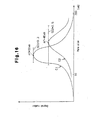
- the ceramic support 15 made of the SiC sintered body has a structure of partitioning with porous cell walls 12 as shown in FIG. 3(a). As shown by a curve C1 in a graph of FIG. 16, the ceramic support 15 is necessary to have an average pore size m1 of 10-250 ⁇ m as measured by a mercury pressure process.
- the average pore size m1 is preferably within a range of 10-150 ⁇ m or 10-100 ⁇ m.
- the cell wall 12 has such a pore size, it is preferable to catch fine particulates. That is, when the average pore size m1 of the cell wall 12 is set to the above range, diesel particulates included in the exhaust gas can be caught at a low pressure loss.
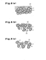
- the average pore size is less than 10 ⁇ m, as shown in FIG. 6(a), the pore size is made smaller by the catalyst coat layer 2 and hence the pressure loss is considerably increased to cause the stop of the engine. And also, as the average pore size becomes large, the increase of the pressure loss due to the catalyst coat layer 2 is suppressed.
- FIG. 6(a) shows that the average pore size is less than 10 ⁇ m, as shown in FIG. 6(a)
- the pore size is made smaller by the catalyst coat layer 2 and hence the pressure loss is considerably increased to cause the stop of the engine.
- the average pore size becomes large, the increase of the pressure loss due to the catalyst coat layer 2 is suppressed.
- soot 16 when soot 16 is caught, soot 16 deposits even in pores inside the wall when the pore size exceeds 50 ⁇ m (deep layer filtration). Furthermore, as shown in FIG. 6(c), when the pore size exceeds 250 ⁇ m, the soot aggregates and soot 17 bridged between the pores of the wall are pointedly existent in the wall.
- the soot 16 is secondary particulate aggregate of carbon fine particles degrading permeation of gas and hence the pressure loss becomes very high when passing through the soot layer. Therefore, it is possible to control the increase of the pressure loss when the average pore size is set to be the above range.
- a standard deviation D1 of pore size distribution when the pore size is represented by a common logarithm is required to be not more than 0.40.
- the standard deviation D1 is preferably not more than 0.30, particularly not more than 0.20.
- the standard deviation of the pore size distribution is desirable to be 0.05-0.40. Because the strength when the catalyst is coated on the ceramic particles is highest (FIG. 19(c)).
- the standard deviation is less than 0.05, the pore size is too uniform and the crack easily progresses due to temperature rising and the fracture strength lowers.
- the standard deviation is more than 0.40, large pores can be obtained and the fracture strength considerably lowers. That is, when the catalyst layer is formed on the ceramic particles, if the temperature is raised to 300°C, it is considered that the catalyst coat layer of catalyst metal, alumina and the like expands to enlarge a space between the particles to thereby cause crack because there is a difference in thermal expansion coefficient to the catalyst support. Therefore, when the distribution of the pore size is uniform, the temperature of the filter in use rises and hence the crack progress and the strength lowers. And also, when the pore distribution is large, the lowering of the strength becomes remarkable in the portion having a large pore size and the strength lowers. Therefore, when the catalyst layer is formed on the ceramic particles, the difference in the strength is caused.
- the average pore size of the ceramic support 15 is set to 10-250 ⁇ m and porosity of the ceramic support 15 is set to 40-80%, so that the pressure loss can be lowered but also the mechanical strength can be improved. In addition, the catching efficiency of particulate included in the exhaust gas can be enhanced.
- such compounded starting materials are mixed and milled and shaped into a honeycomb through an extrusion shaping, and a part of the resulting cells are sealed in a checkered pattern.
- the shaped body is dried at 100-200°C, degreased at 300-500°C and fired in an inert atmosphere at 1800-2400°C for 4-30 hours to obtain a desired ceramic support 15.
- the ceramic support 15 having relatively large average pore size and porosity according to the embodiment of the invention can be prepared, for example, by the following method.
- the pore forming agent made of the substance dissipating by heat at a stage before arriving to the sintering temperature of the ceramic is previously added to the shaped body made of the ceramic starting materials and the firing is carried out at such a state.
- the firing is carried out at such a state.
- the pore forming agent When the firing is carried out at a state of adding the pore forming agent, the pore forming agent is dissipated by heat at a stage before arriving at the sintering temperature of the ceramic and a large pore is formed in a place corresponding to the presence of the pore forming agent. Therefore, the large pore having desired size and shape can be formed relatively simply and surely. Moreover, the pore forming agent is dissipated and hardly remains in the texture of the ceramic support 15. Therefore, this method has a merit that the degradation of the properties in the sintered body due to the incorporation of impurities can previously be prevented.
- the pore forming agent is added at a stage of preparing the ceramic starting material and uniformly milled with the other materials.
- the pore forming agent is favorable to be concretely a substance dissipating by heat at a stage before arriving at the sintering temperature of silicon carbide (about 2200°C).
- the term "dissipating by heat” means that the substance is substantially lost from the sintered body by sublimation, evaporation, decomposition, reaction sintering or the like through heat.
- the dissipating temperature is desirable to be low, and is concretely not higher than 1000°C and particularly preferable to be not higher than 500°C.
- the pore forming agent is desirable not to accompany foaming in the dissipation. Because, in case of the pore forming agent accompanying the foaming, it is difficult to form large pores having uniform size and shape, which has a fear of influencing upon the quality of the ceramic support 15.
- the pore forming agent there are particles of synthetic resin and the like.
- particles made of an organic polymer such as starch and the like may be used.
- a spherically granular pore forming agent made of the synthetic resin is used.
- the merit of using the particles of the synthetic resin as the pore forming agent lies in a point that it is surely dissipated by heat at a relatively premature stage before arriving at the sintering temperature of silicon carbide.
- the synthetic resin is comprised of a relatively simple molecule structure and is small in the possibility of producing a complicated compound by heating and hence impurities resulting in the degradation of the properties of the sintered body hardly remain in the ceramic support 15.
- the synthetic resin is a relatively cheap material, and it does not bring about the increase of the production cost of the ceramic support 15.
- the shape of the pore forming agent is not limited to the sphere but may be, for example, an elongated sphere, a cube, an indefinite lump, a column, a plate or the like.
- the average particle size of the pore forming agent may be set to the objective pore size, for example, about 5 ⁇ m-250 ⁇ m.
- the pore forming agent dissipating by firing is added to the starting material at an amount required from a calculation of dissipation volume for a desired porosity.
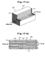
- the catalyst As a method of holding the catalyst, it is not particularly limited to the following method, but it is effective to cover the surface of the cell wall 12 substantially constituting the ceramic support 15, particularly the surface of each sintered SiC particle 4 constituting the cell wall 12 with the rare earth oxide-containing alumina thin film 3. More accurately, the surfaces of the SiC particles 4 in the SiC sintered body constituting the cell wall 12 are individually covered with the rare earth oxide-containing alumina thin film 3 by various methods.
- FIG. 17(b) shows such a conventional technique that the catalyst coat layer 2 is uniformly covered and formed onto the surface of the cell wall 12 by a wash-coat method
- FIG. 3(a) and FIG. 3(b) are diagrammatic views of embodiments of the ceramic support 15 according to the invention.
- the latter shows a state that the surfaces of the SiC particles constituting the cell wall 12 are individually covered with the rare earth oxide-containing alumina thin film 3 (hereinafter abbreviated as alumina thin film 3).
- the above characteristic structure in the catalyst holding filter 10 according to the invention is different from the conventional technique wherein the wall face of the cell wall 12 for the exhaust gas is simply and uniformly covered with the catalyst coat layer 2.
- the ceramic support 15 used in the embodiment of the invention has a structure that each surface of the SiC particles constituting the cell wall 12 is individually covered with the alumina thin film 3.
- the pores of the cell wall 12 itself i.e. spaces produced between the SiC particles 4 are not completely clogged and the pores are maintained as they are.
- the pressure loss can considerably be made small as compared with the conventional catalyst coat layer 2.
- the alumina thin film 3 individually covers each SiC particle 4 itself, so that there is no peeling of the thin film from the cell wall 12 in the washing with water.
- the washing resistance can be improved.
- the contacting area between the exhaust gas and the catalyst is made large. As a result, oxidation of CO, HC in the exhaust gas can be promoted.
- the pressure loss property when the exhaust gas passes through the cell wall 12 is considered as follows. That is, the pressure loss when the diesel exhaust gas passes through the ceramic support 15 can be shown in FIG. 4.
- ⁇ P4 is a resistance when passing through deposited diesel particulates and is a value higher than 2-3 times the initial pressure loss.
- a specific surface area of the ceramic support 15 having a cell structure of 14/200 is 8.931 cm 2 /cm 3 and a density of the ceramic support 15 is 0.675 g/cm 3
- a specific surface area of the cell wall 12 is 0.0013 m 2 /g.
- a specific surface area of a pore in the cell wall 12 is 0.12 m 2 /g as measured by a mercury pressure process, and the pore has a surface area of about 50-100 times.
- the thickness of the alumina thin film 3 can be made to 1/50-1/100 for obtaining the same effect.
- the thickness of the alumina thin film 3 is required to be 50 ⁇ m.
- the pressure loss the resistance passing through the alumina thin film 3 increases in addition to the resistance ⁇ P3 passing through the cell wall 2.
- the opening is small and ⁇ P1 becomes large.
- the pressure loss is considerably large as compared with the filter not coated with the alumina, and this tendency becomes more remarkable when the particulate is deposited on the filter.
- the thickness is about 0.5 ⁇ m at maximum.
- the resistance ⁇ P3 slightly increases, but the other pressure losses are substantially ignored and hence the pressure loss property is considerably improved as compared with the alumina layer formed by the conventional wash coat method.
- alumina has a higher specific surface area and is suitable as a film holding the catalyst. Particularly, it is desired to develop the catalyst holding filter 10 stably operating at a higher temperature and having a high heat resistance at the present time, so that the alumina thin film 3 is also required to have a more higher heat resistance.
- each alumina particle is rendered into a fine fiber, and (2) a rare earth oxide such as ceria ( cerium oxide) or the like is included in order to improve the heat resistance of the alumina.
- a rare earth oxide such as ceria ( cerium oxide) or the like is included in order to improve the heat resistance of the alumina.
- contact points between alumina particles can be decreased by adopting the construction of the former (1), and the grain growth is controlled through the lowering of the sintering rate and hence the specific surface area can be increased to improve the heat resistance.
- the alumina thin film 3 covering the each surface of the SiC particles 4 in the ceramic support 15 according to the invention the micro-sectional shape of each alumina particle indicates a haired structure of foresting small fibers. Therefore, mutually contact points between adjoining alumina small fibers are decreased to considerably improve the heat resistance.
- the heat resistance is improved by adding ceria or the like. Because, a new compound is formed on the surface of the crystal grains constituting the alumina thin film 3 to provide an effect of preventing the growth of the alumina grains.
- Si is supplied from SiC or SiO 2 existing on slight surface layer thereof in the heat treatment and serves as an action of shielding the mass transfer path to improve the heat resistance. According to the inventors' studies, it has been confirmed that when SiC is intentionally treated at a high temperature to form an oxide film, the heat resistance is further improved.
- the particulate deposited on the surface of the cell wall 12 is mainly composed of carbon, which can be removed by oxidation through a method such as combustion or the like.
- a substance leaving as an ash is existent after the combustion.
- Such a substance is an oxide or a sulfate of a compound of Ca, Mg, Zn or the like added in an engine oil for serving as a neutralizing agent, a lubricant or the like.
- a catalyst previously included in a fuel for combusting carbon such as CeO 2 , CuO or the like is deposited together with the particulate.
- a thick coat layer is existent on the whole surface of the cell wall 12 through physical adsorption, so that it is frequently peeled off in the above washing.
- the holding film (alumina thin film 3) used in the embodiment of the invention alumina is thinly and individually coated on each surface of the SiC particles 4 constituting the ceramic support 15.
- Si is supplied from SiC constituting the ceramic support 15 and chemically bonded. As a result, it is at a state of rigidly adhering to each of SiC particles. Therefore, the resistance to washing is high and the durability as a film is strong.
- the alumina thin film 3 is added with a rare earth oxide such as ceria (CeO 2 ) or lanthana (La 2 O 3 ) in an amount of 10-80 mass%, preferably 20-40 mass% based on Al 2 O 3 , in which these oxides are uniformly dispersed in the surface or inside of the alumina thin film 3.
- a rare earth oxide such as ceria (CeO 2 ) or lanthana (La 2 O 3 ) in an amount of 10-80 mass%, preferably 20-40 mass% based on Al 2 O 3 , in which these oxides are uniformly dispersed in the surface or inside of the alumina thin film 3.
- the supply of oxygen into the exhaust gas is activated by the action of ceria adjusting an oxygen concentration to improve a combustion removing efficiency of "soot (diesel particulate)" adhered to the filter.
- the regeneration ratio of the catalyst holding filter 10 is considerably improved.
- the durability of the catalyst holding filter 10 can be improved.
- the rare earth oxide such as ceria or the like not only improves the heat resistance of alumina but also adjusts the oxygen concentration on the surface of the catalyst holding filer 10.
- hydrocarbon and carbon monooxide included in the exhaust gas are removed by oxidation reaction and NOx is removed by reduction reaction, but the composition of the exhaust gas always changes between rich zone and lean zone in the fuel and hence an atmosphere acting on the surface of the catalyst holding filter 10 violently changes.
- Ceria added to the catalyst is relatively low in the oxidation-reduction potential between Ce 3+ and Ce 4+ and reversibly promotes the following reaction. 2CeO 2 ⁇ Ce 2 O 3 + 1/2O 2
- the above reaction progresses in a right direction to supply oxygen to the atmosphere, while as the exhaust gas becomes lean zone, the reaction progresses in a left direction to occlude extra oxygen in the atmosphere.
- the oxygen concentration in the atmosphere is adjusted, so that the ceria acts to widen a breadth of air-fuel ratio capable of efficiently removing hydrocarbon, carbon monooxide or NOx.
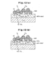
- FIG. 12 (a) explains a mechanism of oxidation rate of the alumina thin film 3 not added with ceria (CeO 2 ).
- FIG. 12 (b) explains a mechanism of oxidation rate of the alumina thin film 3 added with ceria.
- the catalyst having no ceria activates oxygen in the exhaust gas to oxidize soot. This reaction is poor in the efficiency because oxygen in the fluid should be activated.
- oxygen discharged into the atmosphere and oxygen in the exhaust gas are activated by the catalyst (noble metal) to react with soot (carbon) to produce CO 2 (CeO 2-x is oxidized to return to CeO 2 ). And also, CeO 2 and soot directly contact with each other, so that even if a quantity of oxygen discharged is small, the soot can efficiently be oxidized.
- CeO 2 holds the catalyst (noble metal) to increase OSC (oxygen storing capacity). Because, the catalyst (noble metal) activates oxygen in the exhaust gas and also activates oxygen on the surface of CeO 2 in the vicinity of the noble metal to increase the above OSC.
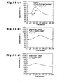
- FIG. 13 and FIG. 14 show experimental results on regeneration properties of a catalyst holding filter 10 (invention embodiment) comprising Pt as a catalyst, CeO 2 as a cocatalyst and needle-shaped Al 2 O 3 as a support material and a catalyst holding filters 10 of Pt/needle-shaped Al 2 O 3 (comparative example) and Pt/Al 2 O 3 (wash coat) for the effect of adding a rare earth oxide such as ceria or the like to the alumina thin film 3.
- a catalyst holding filter 10 comprising Pt as a catalyst, CeO 2 as a cocatalyst and needle-shaped Al 2 O 3 as a support material and a catalyst holding filters 10 of Pt/needle-shaped Al 2 O 3 (comparative example) and Pt/Al 2 O 3 (wash coat) for the effect of adding a rare earth oxide such as ceria or the like to the alumina thin film 3.
- DPF diesel particulate filter adhered with soot
- fill length 150 mm
- a diesel engine of 1100 rpm and 3.9 Nm is connected thereto, during which a change of a filter temperature (measured at a position of 145 mm from an inlet port) (FIG. 13) when an exhaust gas (350°C) and regeneration(combustion) rate (ratio of temperature rising ⁇ T to lapse time ⁇ t, FIG. 14) are measured.
- the conventional example (catalyst coat layer 2 formed by wash coat) produces a peak temperature at 50 sec-700°C as O 2 becomes rate-determining
- the comparative example no ceria (cocatalyst)
- a high peak temperature produces at a faster rate of 45 sec-900°C, which shows a higher oxidation removal efficiency of soot and a higher regeneration ratio. This also clearly appears as a difference of regeneration (combustion) rate in FIG. 14.
- FIG. 15 shows a comparison of the regeneration ratio, from which it is clear that the effect of the invention example (ceria-containing catalyst) is remarkable.
- DPF filters the soot in the exhaust gas. Therefore, the soot deposits in the inside of the DPF. The action of removing the deposited soot is called as regeneration. Therefore, a ratio of regenerated soot weight to deposited soot weight is represented by a percentage, which is defined as a regeneration ratio.
- the rare earth oxide it is more favorable to use a composite oxide of, for example, a rare earth element and zirconium in addition to the above single oxide (CeO 2 ). It is considered that the property of controlling the oxygen concentration can be improved by including zirconium oxide in the rare earth oxide through the control of the grain growth by the rare earth oxide.
- the rare earth oxide forming the composite oxide with zirconium is favorable to have a particle size of about 1-30 nm, more preferably 2-20 nm.
- the particle size is less than 1 nm, it is difficult to form the composite oxide, while when the particle size exceeds 30 nm, the particles are apt to be sintered and the surface area of the particle becomes small and hence the contact area with the exhaust gas becomes small and a problem of weakening the activity remains. Further, there is a fear of increasing the pressure loss in the passing of the exhaust gas.
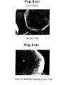
- FIG. 5 shows a comparison between an electron microphotograph (x20000) of the ceramic support 15 in which each surface of SiC particles 4 is covered with the alumina thin film 3 and an electron microphotograph (x5000) of the support in which the surface of the cell wall 12 is uniformly covered with alumina film (conventional technique). It is apparently seen that needle-shaped (small fibrous) alumina is forested on the surface of each SiC particle 4, which indicates a haired structure as shown in FIG. 3(b).
- Such a structure of the alumina thin film 3, i.e. crystal structure of alumina thin film 3 formed by covering each surface of SiC particles 4 contains at least one of ⁇ -Al 2 O 3 , ⁇ -Al 2 O 3 and ⁇ -Al 2 O 3 .
- the small fiber protruded alumina constituting the alumina thin film 3 has a diameter of 2-50 nm, a length of 20-300 nm and a ratio of full length/diameter of 5-50.
- the alumina thin film 3 having such a structure is favorable to have a thickness of not more than 0.5 ⁇ m and a specific surface area of alumina of 50-300 m 2 /g based on alumina.
- the above-mentioned thickness of the alumina thin film 3 is the average distance between each surface of SiC particles 4 and each edge of the small fiber protruded alumina. Furthermore, the diameter of the alumina is more desirable to be 5-20 nm and the ratio of the full length/diameter is more desirable to be 10-30.
- the reason why the properties of the small fiber protruded alumina thin film 3 are restricted as mentioned above is due to the fact that when the length of the small fiber protruded alumina is less than 20 nm, it is difficult to ensure the required specific surface area, while when it exceeds 300 nm, the structure becomes brittle. And also, when the diameter is less than 2 nm, it is equal to or smaller than the size of the catalyst such as noble metal or the like and does not serve as a catalyst holding layer, while when it exceeds 50 nm, it is difficult to ensure the desirable specific surface area. Furthermore, when the ratio of full length/diameter is less than 5, it is difficult to ensure the required specific surface area, while when it exceeds 50, the structure becomes brittle and there may be caused the breaking of the small fiber protrusion by the washing operation or the like.
- the reason why the specific surface area of the alumina thin film 3 is restricted as mentioned above is due to the fact that when it is less than 50 m 2 /g, the sintering of the small fiber protruded alumina excessively progresses and the durability becomes poor. On the other hand, when the specific surface area exceeds 300 m 2 /g, the small fiber protruded alumina is too finer and does not serve as so-called catalyst holding layer or becomes structurally brittle. Moreover, a preferable specific surface area is a range of 50-200 m 2 /g.
- an amount of alumina thin film 3 as a holding film in the ceramic support 15 is favorable to be 0.1-15 mass% at an alumina ratio.
- it is less than 0.1 mass%, the effect of improving the heat resistance becomes small, while when it exceeds 15 mass%, the pressure loss increases and the filter function lowers. More preferably, it is 1-4 mass%.
- the silicon content is favorable to be 0.01-10 mass%.
- the silicon content is less than 0.01 mass%, a capacity of supplying Si is lacking and the effect of improving the heat resistance is small, while when the silicon content exceeds 10 mass%, the strength of the honeycomb filter lowers.
- This silicon content is applied to the other silicon-containing ceramic, which is preferably 0.01-10 mass%, more preferably 0.01-5 mass%, particularly 0.01-2 mass%.
- the surface of the ceramic support 15 indicates a state of completely covering with the alumina thin film (holding film) 3.
- a noble metal element as a catalyst and an element selected from Group VIa and Group VIII in the Periodic Table.
- these elements include platinum (Pt), palladium (Pd), rhodium (Rh), nickel (Ni), cobalt (Co), molybdenum (Mo), tungsten (W), cerium (Ce), copper (Cu), vanadium (V) , iron (Fe), gold (Au), silver (Ag) and so on.
- At least one element selected from Pt, Au, Ag, Cu as a noble metal, Mo, W as an element of Group VIa in the Periodic Table, Fe, Co, Pd, Rh, Ni as an element of Group VIII in the Periodic Table and V, Ce as an element other than the above in the Periodic Table or a compound thereof is held as a catalyst on the alumina thin film 3.
- binary alloy or ternary alloy based on a combination of the above elements is used as the compound.
- These alloys are advantageous to be used together with the rare earth oxide such as ceria or lanthana acting as a cocatalyst as previously mentioned.
- Such a catalyst holding filter 10 is less in the deterioration by poison (lead poison, phosphorus poison, sulfur poison) and small in the heat degradation and hence it is excellent in the durability.
- a compound based on a combination with the other element may be used in addition to the above alloy based on the combination of the elements.
- the binary alloy there are Pt/Pd, Pt/Rh, Pt/Ni, Pt/Co, Pt/Mo, Pt/W, Pt/Ce, Pt/Cu, Pt/V, Pt/Fe, Pt/Au, Pt/Ag, Pd/Rh, Pd/Ni, Pd/Co, Pd/Mo, Pd/W, Pd/Ce, Pd/Cu, Pd/V, Pd/Fe, Pd/Au, Pd/Ag, Rh/Ni, Rh/Co, Rh/Mo, Rh/W, Rh/Ce, Rh/Cu, Rh/V, Rh/Fe, Rh/Au, Rh/Ag, Ni/Co, Ni/Mo, Ni/W, Ni/Ce, Ni/Cu, Ni/V, Ni/Fe, Ni/Au, Co/Mo, Co/W, Co/Ce, Co/Cu, Co/V, Co/Fe,
- impregnation method evaporation drying method, equilibrium adsorption method, incipient wetness method, spray method are applicable.
- the incipient wetness method is advantageous.
- This method is a methof wherein an aqueous solution containing a given amount of a catalyst is added dropwise to the ceramic support 15 and at a time of slightly and uniformly wetting the surface of the support (incipient) the impregnation of the catalyst into the pores of the ceramic support 15 is stopped and thereafter the drying and firing are carried out. That is, it is carried out by adding the catalyst-containing solution dropwise to the surface of the ceramic support 15 with a billet or an injection. A holding amount of the catalyst is determined by adjusting the concentration in the solution.
- the manufacturing method of the catalyst holding filter 10 is described below.
- a characteristic of the manufacturing method of the catalyst filter 10 according to the invention lies in that the alumina thin film 3 containing the rare earth oxide is formed on the irregular surface of the silicon-containing ceramic support 15 by a sol-gel method.
- the rare earth oxide-containing alumina thin film 3 is individually coated on each surface of SiC particles 4 forming the cell wall 12 by the immersion of the solution.
- the micro-section structure of the alumina thin film 3 is changed into an alumina thin film (holding film) 3 indicating such a haired structure that small fibers of alumina dispersed with ceria or the like are forested, and then a given amount of a catalyst is adsorbed and fixed (held) onto the surface of the alumina thin film 3.
- a treatment of oxidizing by heating at 800-1600°C for 5-100 hours is carried out for supplying an amount of Si required for assisting chemical bond to alumina to each surface of SiC particles 4.
- this step may be omitted if a sufficient oxide film is existent on the surface of the SiC particle 4.
- SiC sintered body itself contains about 0.8 mass% of SiO 2 .
- SiO 2 is increased for improving the heat resistance, which is desirable to heat in an oxidizing atmosphere at 800-1600°C for 5-100 hours.
- a recommend condition is 1000-1500°C and 5-20 hours. Under this condition, SiO 2 enough to supply Si can be formed on the surface and the pressure loss property is not damaged without substantially changing the porosity and pore size of the ceramic support 15.
- this step is carried out a treatment that a solution of a metal compound containing aluminum and a rare earth element, for example, an aqueous mixed solution f aluminum nitrate and cerium nitrate is impregnated into each surface of the SiC particles 4 constituting the cell wall 12 by a sol-gel method to coat a rare earth oxide-containing alumina thin film 3.
- a solution of a metal compound containing aluminum and a rare earth element for example, an aqueous mixed solution f aluminum nitrate and cerium nitrate is impregnated into each surface of the SiC particles 4 constituting the cell wall 12 by a sol-gel method to coat a rare earth oxide-containing alumina thin film 3.
- an inorganic metal compound and an organic metal compound are used as a starting metal compound.
- the inorganic metal compound there are used Al(NO 3 ) 3 , AlCl 3 , AlOCl, AlPO 4 , Al 2 (SO 4 ) 3 , Al 2 O 3 , Al(OH) 3 , Al and so on.
- Al(NO 3 ) 3 and AlCl 3 are particularly preferable because they are easily dissolved in a solvent such as water, alcohol or the like and easy in the handling.
- organic metal compound there are metal alkoxides, metal acetylacetonates and metal carboxylates. Concretely, there are Al(OCH 3 ) 3 , Al(OC 2 H 3 ) 3 , Al(iso-OC 3 H 7 ) 3 and so on.
- cerium-containing compound in the aqueous mixed solution Ce(NO 3 ) 3 , CeCl 3 , Ce 2 (SO 4 ) 3 , CeO 2 , Ce(OH) 3 , Ce 2 (CO 3 ) 3 and so on.
- the solvent of the mixed solution at least one or more selected from water, alcohol, diol, polyvalent alcohol, ethylene glycol, ethylene oxide, triethanol amine, xylene and the like is used.
- hydrochloric acid, sulfuric acid, nitric acid, acetic acid, hydrofluoric acid may be added.
- at least one element selected from Ce, La, Pr, Nd, Ba, Ca, Li, K, Sr, Si and Zr or a compound thereof other than oxide (nitrate, chloride, sulfate, hydroxide or carbonate) may be added to the starting material in addition to the rare earth oxide.
- Al(NO 3 ) 3 and Ce(NO 3 ) 3 may be mentioned as a preferable example of the metal compound because they are dissolved in the solvent at a relatively low temperature and are easy in the preparation of the starting solution.
- 1,3-butane diol is recommended as a preferable example of the solvent.
- a first reason of the recommendation is due to the fact that the viscosity is proper and it is possible to form a gel film of a proper thickness on the SiC particle 4 at a gel state.
- a second reason is due to the fact that this solvent forms a metal alkoxide in the solution and is easy to form a metal oxide polymer consisting of oxygen-metal-oxygen bond or a precursor of a metal oxide gel.
- An amount of Al(NO 3 ) 3 is desirable to be 10-50 mass%. When it is less than 10 mass%, alumina amount having a surface area sufficient to maintain a catalyst activity over a long time can not be held, while when it exceeds 50 mass%, a heat generation quantity is large in the dissolution and gelation is easily caused.
- An amount of Ce(NO 3 ) 3 is favorable to be 1-30 mass%. When it is less than 1 mass%, the oxidation of soot can not be promoted, while when it exceeds 30 mass%, the grain growth of CeO 2 after the firing occurs.
- a compounding ratio of Al(NO 3 ) 3 to Ce(NO 3 ) 3 is favorable to be 10:2. Because, as Al(NO 3 ) 3 becomes rich, the dispersibility of CeO 2 particles after the firing can be improved.
- a temperature in the preparation of the impregnation solution of the metal compound is desirable to be 50-130°C. When it is lower than 50°C, the solubility of a solute is low, while when it excceds 130°C, the reaction rapidly proceeds to cause gelation and hence it can not be used as an application solution.
- a stirring time is desirable to 1-9 hours. When it is within the above range, the viscosity of the solution stable.
- ZrO(NO 3 ) 3 or ZrO 2 is used as a zirconium source for forming a composite oxide or solid solution of zirconium in addition to the above example. It is favorable that they are dissolved in water or ethylene glycol to from a mixed solution and then the mixed solution is impregnated, and thereafter the composite oxide is obtained through drying and firing steps.
- the ceramic support 15 is placed in a container and the solution of the metal compounds is filled therein and then deaeration is conducted, a method wherein the solution is flowed into the ceramic support 15 from one side thereof and deaerated from the other side, or the like.
- a vacuum pump or the like in addition to an aspirator may be used. By using such an apparatus can be pulled out air from the pores in the cell wall 12 and hence the solution of the metal compounds can be uniformly applied onto each surface of the SiC particles 4.
- This step is a treatment that volatile component such as NO 2 or the like is removed through evaporation to change the solution into gel to thereby fix onto the surfaces of the SiC particles 4 and at the same time an extra solution is removed, which is carried out by heating at 120-170°C for about 2 hours.
- the heating temperature is lower than 120°C, the volatile component hardly evaporates, while when it exceeds 170°C, the thickness of the gelated film becomes ununiform.
- This step is a treatment that calcination is carried out to remove residual components and form an amorphous alumina thin film 3. Concretely, it is desirable to heat at a temperature of 300-500°C. When the calcining temperature is lower than 300°C, the residual organic substance is hardly removed, while when it exceeds 500°C, Al 2 O 3 is crystallized and the small fibrous protruded boehmite can not be formed by a subsequent hot water treatment.
- This step is a treatment that the calcined ceramic support 15 is immersed in hot water for forming the alumina thin film 3 of the aforementioned structure inherent to the embodiment of the invention.
- the particles of the amorphous alumina thin film 3 are discharged into the solution at a sol state by defloculation action and boehmite particles produced by hydration aggregate into small fibrous protrusions and form a stable state against defloculation.
- the rare earth oxide-containing alumina individually adhered to each surface of the SiC particles 4 by this hot water treatment are forested in small fibers (needle-shaped particles) and indicate so-called haired structure to form coarse surfaces. Therefore, the alumina thin film 3 having a high specific surface area is formed.
- the sintering of alumina mainly progresses by surface diffusion, and the specific surface area violently decreases in the phase transfer into ⁇ -alumina.
- silica is included in the alumina particle, it is considered that this silica fills in the pore site of alumina or moves to the surface of the needle-shaped particle in the course of the heat treatment to suppress the surface diffusion or the sintering between the particles.
- a viscous flowing mechanism through the sintering from a contact point between the needle-shaped particles is preferential in the initial sintering of the ceramic support 15, while silica shuts off the substance-moving path between the needle-shaped particles at the late stage to obstruct the transfer into ⁇ -alumina and hence it is considered that the sintering is not progressed to maintain a higher specific surface area.
- the temperature in the hot water treatment is desirable to be 50-100°C. When it is lower than 50°C, the hydration of the amorphous alumina thin film 3 does not proceed and the small fibrous protruded boehmite is not formed, while when it exceeds 100°C, water evaporates and the step can not be maintained over a long time.
- the treating time is desirable to be not less than 1 hour. When it is less than 1 hour, the hydration of the amorphous alumina is insufficient.
- This step is a treatment that the boehmite produced by hydration is heated to form alumina crystal.
- a preferable firing temperature is 500-1000°C, and a preferable firing temperature is 5-20. When the temperature is lower than 500°C, the crystallization is not promoted, while when it exceeds 1000°C, the sintering excessively proceeds and the surface area tends to be lowered.
- the holding amount of the catalyst is determined by dropwise adding an aqueous solution containing Pt or the like to the ceramic support 15 so as to impregnate by an water absorbing amount thereof at a state of slightly wetting the surface.
- the water absorbing amount of the ceramic support 15 means that when a measured value of water absorbing amount of dry support is 22.46 mass% and a mass of this support is 110 g and a volume thereof is 0.163 1, the support absorbs 24.79/l of water.
- a solution of dinitrodianmine platinum nitrate [Pt(NH 3 ) 2 (NO 2 ) 2 ]HNO 3 , Pt concentration: 4.53 mass%).
- Pt concentration: 4.53% 0.272 g of Pt on the support, so that the solution of dinitrodianamine nitrate (Pt concentration: 4.53%) is diluted with a distilled water.
- the above adjusted aqueous solution of a given amount of dinitrodianamine nitrate is added dropwise to both end faces of the ceramic support 15 at constant intervals with a pipette. For instance, the solution is added dropwise onto the one side face at constant intervals every 40-80 droplets, whereby Pt is uniformly dispersed and fixed onto the surface of the alumina thin film 3 covering the ceramic support 15.
- the ceramic support 15 after the addition of the aqueous solution is dried at 110°C for about 2 hours to remove water. Thereafter, the support is placed in a desiccator and left to stand for 1 hour to measure an adhesion amount by means of an electron balance or the like. Then, the firing is carried out in N2 atmosphere at about 500°C for about 1 hour to conduct metallization of Pt.
- the catalyst holding filter 10 is used as a filter for the purification of the exhaust gas.
- plain honeycomb ceramic support 15 there are an oxidation catalyst for a gasoline engine, a ternary catalyst and an oxidation catalyst for a diesel engine.
- the diesel particulate filter itself has only a function of catching particulate (floated particle matter: PM), but when the catalyst is held to the filter, hydrocarbon and carbon monooxide in the exhaust gas can be oxidized.
- the catalyst holding filter 10 according to the invention is said to be particularly favorable for application to a diesel exhaust gas treating system, but the following functions can be expected.
- a first example is carried out for confirming action and effect when a ceria-containing alumina thin film 3 is held on a surface of a ceramic support 15 having varied pore size and porosity.
- the manufacture of the ceramic support is based on the following system.
- silicon carbide powder having a relatively large average particle size (powder A) and silicon carbide powder having a relatively small average particle size (powder B) and, if necessary, silicon carbide powder having a middle average particle size (powder C) are mixed as starting materials.
- a spherical acryl resin (density 1.1 g/cm 3 ) as a pore-forming agent for forming objective porosity and pore size is mixed with the staring silicon carbide powder at a volume ratio.
- methylcellulose as a forming assistant is mixed with the starting silicon carbide powder at a weight ratio.
- a dispersion consisting of an organic solvent and water is mixed at a weight ratio shown in Table 1 based on total of all starting materials. Thereafter, the mixed starting materials are milled and shaped into a honeycomb by extrusion shaping, and then a part of cells 11 is sealed into a checkered pattern, Next, the shaped body is dried at 150°C, degreased at 500°C and fired in an inert atmosphere at a firing temperature and firing time shown in Table 1 to obtain a ceramic support of each example and comparative example.
- the average pore size is measured by a mercury pressure method.
- An average value m2 of the pore size, a porosity and a standard deviation SD2 of pore size distribution represented by a common logarithm of the pore size are shown in Table 1.
- the ceramic support in Examples 6, 17, 18, 19, 20 is connected to an engine and catches soot for 5 hours, and a catching efficiency is calculated from the caught amount.
- the caught soot is washed and 30 g/l of a catalyst coat layer is held on each of the ceramic supports.
- the ceramic support in Examples 6, 17, 18, 19, 20 is heated at 300°C in an electric furnace and thereafter a three-point bending test is carried out every 20 supports. Then, an average of fracture loads is taken. And also, the same bending test is conducted with respect to the support held with 30 g/l of the catalyst coat layer according to the invention and the support coated on the wall as described in JP-A-5-23512. The results are shown in FIG. 19(c).
- the pressure loss is not less than 30 kPa, so that the catching for a long time can not be conducted when being coated on the wall.
- a test is carried out for confirming the action and effect on the ceria-containing alumina thin film 3 formed on a surface of a ceramic support 15.
- a ceramic support 15 produced under conditions shown in Table 2 (Test Example 1, Comparative Test Examples 1, 2) is attached to a particulate filter (DPF) in an exhaust gas purification apparatus of a diesel vehicle to conduct a purification test. According to this test are examined pressure loss property, heat resistance and wash resistance of the filter. The examined results are shown in the same table and FIGS. 7 and 8.
- the average value m2 of the pore size measured by the mercury pressure method is 40 ⁇ m.
- the standard deviation SD2 of the pore size distribution represented by a common logarithm of pore size is 0.50 (curve C2 shown in FIG. 16). Therefore, the catalyst holding filter 10 is rendered into a state of existing many pores having a size suitable for catching the particulate , whereby the particulate can surely be caught. Therefore, a filter 3 having a low pressure loss and a high catching efficiency can be realized.
- This example shows test results on various properties when platinum (Pt) as a catalyst is held on a ceramic support 15 in a diesel particulate filter (DPF).
- the test conditions and properties are shown in Table 3.
- the results are shown in FIGS. 8, 9 and 10.
- this test example has an alumina thin film 3 (8 g/l) on a surface of SiC particle 4 in a ceramic support 15.
- Reference Test Example has not any holding film on the surface of the ceramic support 15.
- Comparative Test example 3 an alumina uniform film is formed on the surface of the ceramic support 15 by wash coat.
- Test Example2 Test Example2 Reference Test Example Comparativ e Test Example Honeycomb support SiC-DPF SiC-DPF SiC-DPF SiC-DPF Cell structure 14/200 14/200 14/200 14/200 Catalyst coat layer Catalyst coat layer on particles on particles on cell wall on cell wall Porosity of ceramic support 45% 45% 45% 45% Pore size of ceramic support 20 ⁇ m 20 ⁇ m 8 ⁇ m 20 ⁇ m Al 2 O 3 content 8g/l 8g/l none 8g/l CeO 2 content 2g/l 1g/l(C e o 2 ) none none 1g/l(ZrO 2 ) Pt content 1.7g/l 1.7g/l none 1.7g/l Pressure loss property PM0g/1(10m/sec) 1 1 1 1.45 PM0g/l(10m/sec) 1 1 1 1.45 Heat resistance of Al 2 O 3 coat FIG.
- Test Examples 2, 3 show a pressure loss property substantially equal to that of Reference Test Example having no holding film and are considerably superior in the effect to Comparative Test Example 3.
- a performance of combusting soot adhered to the catalyst holding filter 10 is evaluated by an equilibrium temperature testing method. That is, a diesel engine is placed in a testing apparatus and the catalyst holding filter (DPF) 10 is inserted on the way of the exhaust pipe, and the running is started at such a state. With the lapse of the running time, soot is caught on the DPF, so that the pressure loss increases. In this case, as the exhaust temperature is raised by any method, a point balancing a rate of depositing soot with an oxidation reaction rate of soot (equilibrium temperature) appears at a certain temperature, while a pressure at this point (equilibrium pressure) can be measured. It can be said that the lower the equilibrium temperature and equilibrium pressure, the better the catalyst holding filter 10.
- DPF catalyst holding filter
- an electric heater is inserted between the diesel engine and the DPF.
- engine revolution number and load can be made constant, so that the composition of the diesel exhaust gas does not vary during the test and the equilibrium temperature and equilibrium pressure can be ensured accurately.
- a steady run of the diesel engine having a displacement of 273 cc is carried out at a revolution number of 1250 rpm under a load of 3 Nm, and a volume of the test filter is 0.17 liter ( ⁇ 34 mm x 150 mm).
- FIG. 10 an example of ceramic support 15 holding no catalyst is Reference Test example.
- the filter temperature rises together with the rise of the exhaust gas temperature, but an equilibrium point is seen at about 500°C.
- Test Example 2 is compared with Comparative Test Example 3, the equilibrium temperature is 400°C and 410°C, respectively, and is slightly significant, but the equilibrium pressure is 11 kPa and 9.2 kPa and is improved by about 20%.
- This property is a general method for evaluating the oxidation catalyst, which examines a relation between purification of so-called THC (all hydrocarbon) into CO2 and water and a purifying temperature of CO into CO2. As the conversion ratio at a low temperature becomes higher, this property is said to provide an excellent catalyst system.
- the filter is arranged in a path of an exhaust gas in an engine. The amounts of THC and CO before and after the filter are measured by an exhaust gas analyzing meter to determine a purification ratio to the temperature.
- Test Example 2 is superior in the performance to Comparative Test Example 3 because the purification temperatures of CO, THC decrease about 30°C.
- the catalyst is uniformly dispersed into the SiC particles 4 of the cell wall 12 in this test example, the time of passing the exhaust gas through the cell wall 12 is clearly longer than the time of passing through the wash coat and as a result, a chance of adsorbing CO, THC on an active point of Pt is increased.
- the contact area of the exhaust gas with the catalyst coat layer 2 cam be made large. Therefore, the oxidation of CO and HC in the exhaust gas can be promoted.
- the catalyst holding filter being less in the pressure loss of the exhaust gas and improving the mechanical strength. And also, according to the invention, there is provided the catalyst holding filter having a higher catching efficiency of particulate included in the exhaust gas.
Landscapes
- Chemical & Material Sciences (AREA)
- Engineering & Computer Science (AREA)
- Ceramic Engineering (AREA)
- Manufacturing & Machinery (AREA)
- Chemical Kinetics & Catalysis (AREA)
- Inorganic Chemistry (AREA)
- General Chemical & Material Sciences (AREA)
- Materials Engineering (AREA)
- Structural Engineering (AREA)
- Organic Chemistry (AREA)
- Combustion & Propulsion (AREA)
- Oil, Petroleum & Natural Gas (AREA)
- Analytical Chemistry (AREA)
- Health & Medical Sciences (AREA)
- Biomedical Technology (AREA)
- Environmental & Geological Engineering (AREA)
- Life Sciences & Earth Sciences (AREA)
- Geology (AREA)
- Catalysts (AREA)
- Filtering Materials (AREA)
- Processes For Solid Components From Exhaust (AREA)
- Exhaust Gas After Treatment (AREA)
- Exhaust Gas Treatment By Means Of Catalyst (AREA)
- Ultra Sonic Daignosis Equipment (AREA)
Abstract
Description


| Test Example2 | Test Example2 | Reference Test Example | Comparativ e Test Example | ||
| Honeycomb support | SiC-DPF | SiC-DPF | SiC-DPF | SiC-DPF | |
| Cell structure | 14/200 | 14/200 | 14/200 | 14/200 | |
| Catalyst coat layer Catalyst coat layer | on particles | on particles | on cell wall | on cell wall | |
| Porosity of ceramic support | 45% | 45% | 45% | 45% | |
| Pore size of ceramic support | 20 µm | 20 µm | 8 µm | 20 µm | |
| Al2O3 content | 8g/l | 8g/l | none | 8g/l | |
| CeO2 content | 2g/l | 1g/l(Ceo2) | none | none | |
| 1g/l(ZrO2) | |||||
| Pt content | 1.7g/l | 1.7g/l | none | 1.7g/l | |
| Pressure loss property | PM0g/1(10m/sec) | 1 | 1 | 1 | 1.45 |
| PM0g/l(10m/sec) | 1 | 1 | 1 | 1.45 | |
| Heat resistance of Al2O3 coat | FIG. 9 | ||||
| Initial combustion property of soot | equilibrium temperature | 420°C | 420°C | >480°C | 440°C |
| equilibrium pressure | 9.2kPa | 9.2kPa | - | 1kPa | |
| Combustion property of soot after aging | equilibrium temperature | 420°C | 420°C | - | >480°C |
| equilibrium pressure | 9.2kPa | 9.2kPa | - | - | |
| THC,CO conversion rate | FIG.11 |
- The ceramic material constituting the catalyst holding filter 10 is not necessarily a porous body as in the embodiment, nor a honeycomb structure. That is, it is possible to select a network aggregate of ceramic fibers, a ceramic foam or the like as a filter constituting material.
- The ceramic material constituting the catalyst holding filter 10 is not necessarily limited to silicon carbide as in the embodiment, and is possible to select, for example, silicon nitride, cordierite, sialon or the like.
- The catalyst may not be held on the surface of the porous ceramic material constituting the catalyst holding filter 10.
Claims (15)
- A catalyst holding filter for purification of exhaust gas, characterized in that a catalyst coat layer is formed on particles of a ceramic support having an average pore size of 10-250 µm and a porosity of 40-80%.
- A catalyst holding filter for purification of exhaust gas, characterized in that a catalyst coat layer comprising a catalyst, a cocatalyst and a support material is formed on particles of a ceramic support having an average pore size of 10-250 µm and a porosity of 40-70%.
- A catalyst holding filter according to claim 1 or 2, wherein the catalyst contains an element selected from noble metal element, element of Group VIa of the periodic table and element of Group VIII of the periodic table.
- A catalyst holding filter according to any one of claims 1-3, wherein the cocatalyst is at least one element selected from cerium (Ce), lanthanum (La), barium (Ba) and calcium (Ca) or a compound thereof.
- A catalyst holding filter according to any one of claims 1-4, wherein the support material contains at least one selected from alumina, zirconia, titania and silica.
- A catalyst holding filter according to any one of claims 1-5, wherein the ceramic support is silicon carbide, silicon nitride, cordierite, mullite, sialon, silica or zirconium phosphate.
- A catalyst holding filter according to any one of claims 1-6, wherein the ceramic support has a honeycomb structure having plural through-holes defined by cell walls.
- A catalyst holding filter according to claim 7, wherein the ceramic support has a checkered pattern formed by alternately sealing both end portions with sealing bodies.
- A catalyst holding filter according to any one of claims 1-8, wherein the average pore size is measured by a mercury pressure process and a standard deviation of pore size distribution when the pore size is represented by a common logarithm is not more than 0.40.
- A catalyst holding filter according to any one of claims 1-8, wherein the average pore size is measured by a mercury pressure process and a standard deviation of pore size distribution when the pore size is represented by a common logarithm is not more than 0.20.
- A catalyst holding filter according to claim 1, wherein the average pore size is set to 10-100 µm and the porosity of the ceramic support is set to 50-80%.
- A catalyst holding filter according to claim 1 or 2, wherein the catalyst contains an element selected from cerium (Ce), copper (Cu), vanadium (V) , iron (Fe), gold (Au), silver (Ag), platinum (Pt), palladium (Pd), rhodium (Rh), nickel (Ni), cobalt (Co), molybdenum (Mo) and tungsten (W).
- A catalyst holding filter according to claim 7, wherein both end portions of the ceramic support are sealed with sealing members in a checkered pattern, and positions to be sealed differ between one end and the other end of the ceramic support.
- An apparatus for purification of exhaust gas comprising a casing arranged in an exhaust path of an internal combustion engine and a ceramic support arranged in the casing and removing particulate included in an exhaust gas, characterized in that an average pore size of the ceramic support is set to 10-250 µm and a porosity thereof is set to 40-70%, and a catalyst coat layer comprising a catalyst, a cocatalyst and a support material is formed on particles of the ceramic support.
- An apparatus for purification of exhaust gas according to claim 8, wherein a standard deviation (SD1) of pore size distribution is not more than 0.20.
Priority Applications (1)
| Application Number | Priority Date | Filing Date | Title |
|---|---|---|---|
| EP06019557A EP1776994B1 (en) | 2000-09-29 | 2001-10-01 | Catalyst-carrying filter |
Applications Claiming Priority (5)
| Application Number | Priority Date | Filing Date | Title |
|---|---|---|---|
| JP2000299962 | 2000-09-29 | ||
| JP2000299962 | 2000-09-29 | ||
| JP2001048401 | 2001-02-23 | ||
| JP2001048401 | 2001-02-23 | ||
| PCT/JP2001/008649 WO2002026351A1 (en) | 2000-09-29 | 2001-10-01 | Catalyst-carrying filter |
Related Child Applications (1)
| Application Number | Title | Priority Date | Filing Date |
|---|---|---|---|
| EP06019557A Division EP1776994B1 (en) | 2000-09-29 | 2001-10-01 | Catalyst-carrying filter |
Publications (2)
| Publication Number | Publication Date |
|---|---|
| EP1338322A1 true EP1338322A1 (en) | 2003-08-27 |
| EP1338322A4 EP1338322A4 (en) | 2005-01-19 |
Family
ID=26601194
Family Applications (2)
| Application Number | Title | Priority Date | Filing Date |
|---|---|---|---|
| EP01970324A Ceased EP1338322A4 (en) | 2000-09-29 | 2001-10-01 | CATALYST EQUIPPED FILTER |
| EP06019557A Expired - Lifetime EP1776994B1 (en) | 2000-09-29 | 2001-10-01 | Catalyst-carrying filter |
Family Applications After (1)
| Application Number | Title | Priority Date | Filing Date |
|---|---|---|---|
| EP06019557A Expired - Lifetime EP1776994B1 (en) | 2000-09-29 | 2001-10-01 | Catalyst-carrying filter |
Country Status (5)
| Country | Link |
|---|---|
| US (1) | US7625529B2 (en) |
| EP (2) | EP1338322A4 (en) |
| JP (2) | JP2002530175A (en) |
| ES (1) | ES2385213T3 (en) |
| WO (1) | WO2002026351A1 (en) |
Cited By (27)
| Publication number | Priority date | Publication date | Assignee | Title |
|---|---|---|---|---|
| EP1493484A1 (en) * | 2003-07-02 | 2005-01-05 | Haldor Topsoe A/S | Diesel particulate filter |
| EP1403231A4 (en) * | 2001-05-31 | 2005-04-13 | Ibiden Co Ltd | POROUS CERAMIC FRIDGE BODY AND PROCESS FOR PRODUCING THE SAME, AND PARTICULATE GASOIL FILTER |
| EP1624164A1 (en) * | 2004-08-05 | 2006-02-08 | Hitachi, Ltd. | Exhaust gas purification filter for diesel internal combustion engine and method for manufacturing the same and exhaust gas purification apparatus |
| WO2007003428A1 (en) | 2005-07-05 | 2007-01-11 | Helsa-Automotive Gmbh & Co. Kg | POROUS ß-SIC-CONTAINING CERAMIC MOLDED ARTICLE COMPRISING AN ALUMINUM OXIDE COATING, AND METHOD FOR THE PRODUCTION THEREOF |
| FR2891472A1 (en) * | 2005-09-30 | 2007-04-06 | Saint Gobain Ct Recherches | Production of a homogeneous multi-element filter for use in catalytic filters for cars, involves selecting filter elements on the basis of a pre-determined criterion of homogeneity for the uncoated support material |
| EP1775008A1 (en) * | 2005-10-12 | 2007-04-18 | Ibiden Co., Ltd. | Honeycomb unit and honeycomb structured body |
| EP1795262A4 (en) * | 2004-09-30 | 2007-06-13 | Ibiden Co Ltd | ALVEOLAR STRUCTURE |
| EP1839720A1 (en) * | 2006-03-31 | 2007-10-03 | Ibiden Co., Ltd. | Honeycomb structural body and method of manufacturing honeycomb structural body. |
| EP1808228A4 (en) * | 2004-09-02 | 2008-02-13 | Ibiden Co Ltd | BEAT NEST STRUCTURE, PRODUCTION METHOD AND EXHAUST GAS PURIFYING DEVICE |
| EP1916029A1 (en) * | 2006-10-23 | 2008-04-30 | Haldor Topsoe A/S | Method and apparatus for the purifiction of exhaust gas from a compression ignition engine |
| WO2008113802A3 (en) * | 2007-03-19 | 2008-11-27 | Umicore Ag & Co Kg | Particulate filter arrangement |
| EP1552882A4 (en) * | 2002-10-18 | 2009-07-01 | Ngk Insulators Ltd | CATALYTIC MATERIAL BASED ON SILICON CARBIDE AND PROCESS FOR PRODUCING THE SAME |
| EP1787968A4 (en) * | 2004-09-30 | 2009-07-01 | Ibiden Co Ltd | METHOD FOR MANUFACTURING POROUS ARTICLE, POROUS ARTICLE, AND ALVEOLAR STRUCTURE |
| EP1759754A4 (en) * | 2004-06-25 | 2009-07-01 | Ibiden Co Ltd | Filter, method for producing same and exhaust purification system |
| US7648932B2 (en) | 2005-07-05 | 2010-01-19 | Mann+Hummel Innenraumfilter Gmbh & Co. Kg | Molded porous ceramic article containing beta-SiC and process for the production thereof |
| WO2010076509A1 (en) * | 2008-12-17 | 2010-07-08 | Saint-Gobain Centre De Recherches Et D'etudes Europeen | Purification structure including a catalysis system supported by a zircon in reduced state |
| US7759276B2 (en) | 2004-07-23 | 2010-07-20 | Helsa-Automotive Gmbh & Co. Kg | Adsorptive formed body having an inorganic amorphous supporting structure, and process for the production thereof |
| US7785695B2 (en) | 2003-10-20 | 2010-08-31 | Ibiden Co., Ltd. | Honeycomb structured body |
| US7842372B2 (en) | 2007-07-03 | 2010-11-30 | Tyk Corporation | Honeycomb structure |
| WO2011092525A1 (en) * | 2010-02-01 | 2011-08-04 | Johnson Matthey Plc | Filter comprising combined soot oxidation and nh3-scr catalyst |
| EP1920838A4 (en) * | 2005-08-31 | 2012-01-25 | Ngk Insulators Ltd | BEE NEST STRUCTURE AND CATALYTIC SUBSTANCE OF A BEE NID |
| EP1920834A4 (en) * | 2005-08-31 | 2012-01-25 | Ngk Insulators Ltd | HONEYCOMB CATALYST AND METHOD FOR PRODUCING THE SAME |
| EP1920840A4 (en) * | 2005-08-31 | 2012-01-25 | Ngk Insulators Ltd | HONEYCOMB STRUCTURE AND CATALYTIC STRUCTURE OF HONEYCOMB |
| US8122603B2 (en) | 2003-08-05 | 2012-02-28 | Basf Corporation | Method of forming a catalyzed selective catalytic reduction (SCR) filter |
| EP1566214B1 (en) * | 2002-11-22 | 2013-02-27 | NGK Insulators, Ltd. | Catalyst body |
| US9138731B2 (en) | 2011-08-03 | 2015-09-22 | Johnson Matthey Public Limited Company | Extruded honeycomb catalyst |
| EP2832447A4 (en) * | 2012-03-29 | 2015-12-02 | Kubota Kk | CERAMIC FILTER |
Families Citing this family (133)
| Publication number | Priority date | Publication date | Assignee | Title |
|---|---|---|---|---|
| JP4642955B2 (en) * | 1999-06-23 | 2011-03-02 | イビデン株式会社 | Catalyst support and method for producing the same |
| WO2001036097A1 (en) | 1999-11-16 | 2001-05-25 | Ibiden Co., Ltd. | Catalyst and method for preparation thereof |
| JP2002242655A (en) * | 2001-02-15 | 2002-08-28 | Ibiden Co Ltd | Filter for collecting particulate in exhaust gas |
| CN100427730C (en) | 2002-02-05 | 2008-10-22 | 揖斐电株式会社 | Honeycomb filter for exhaust gas purification, adhesive, coating material, and method for producing honeycomb filter for exhaust gas purification |
| WO2003067042A1 (en) | 2002-02-05 | 2003-08-14 | Ibiden Co., Ltd. | Honeycomb filter for exhaust gas decontamination |
| EP1604719B1 (en) | 2002-03-15 | 2008-07-16 | Ibiden Co., Ltd. | Ceramic filter for exhaust gas purification |
| DE60317174T3 (en) * | 2002-03-22 | 2013-01-17 | Ibiden Co., Ltd. | METHOD OF PREPARING A WAVE FILTER FOR CLEANING EXHAUST GAS |
| JP4303599B2 (en) * | 2002-03-25 | 2009-07-29 | イビデン株式会社 | Exhaust gas purification filter |
| DE10214343A1 (en) * | 2002-03-28 | 2003-10-09 | Omg Ag & Co Kg | Filter for removing particulates from diesel engine exhaust gas has a catalytic coating comprising barium and magnesium compounds and a platinum-group metal |
| ATE411095T1 (en) * | 2002-03-29 | 2008-10-15 | Ibiden Co Ltd | CERAMIC FILTER AND EXHAUST GAS DECONTAMINATION UNIT |
| WO2003084640A1 (en) * | 2002-04-09 | 2003-10-16 | Ibiden Co., Ltd. | Honeycomb filter for clarification of exhaust gas |
| WO2003093657A1 (en) * | 2002-04-10 | 2003-11-13 | Ibiden Co., Ltd. | Honeycomb filter for clarifying exhaust gas |
| WO2003093658A1 (en) * | 2002-04-11 | 2003-11-13 | Ibiden Co., Ltd. | Honeycomb filter for clarifying exhaust gas |
| EP1378288A3 (en) * | 2002-04-18 | 2004-01-14 | Ford Global Technologies, LLC, A subsidary of Ford Motor Company | Platinum-group-metal free catalytic washcoats for particulate exhaust gas filter applications |
| DE10238770A1 (en) * | 2002-08-23 | 2004-03-11 | Umicore Ag & Co.Kg | Device for removing soot particles from the exhaust gas of a diesel engine |
| JPWO2004024295A1 (en) | 2002-09-13 | 2006-01-05 | イビデン株式会社 | Honeycomb structure |
| US7326270B2 (en) * | 2002-09-13 | 2008-02-05 | Ibiden Co., Ltd. | Filter |
| JP4437084B2 (en) * | 2002-10-07 | 2010-03-24 | イビデン株式会社 | Honeycomb structure |
| EP1550646A4 (en) * | 2002-10-07 | 2006-04-26 | Ibiden Co Ltd | STRUCTURAL BODY IN HONEYCOMB |
| JP2004188303A (en) * | 2002-12-10 | 2004-07-08 | Ngk Insulators Ltd | Ceramic honeycomb filter |
| CN1326593C (en) | 2003-02-28 | 2007-07-18 | 揖斐电株式会社 | Ceramic honeycomb structure |
| JP4381011B2 (en) * | 2003-03-14 | 2009-12-09 | 東京窯業株式会社 | Silicon carbide honeycomb structure and ceramic filter using the same |
| JP4426525B2 (en) * | 2003-03-20 | 2010-03-03 | 日本碍子株式会社 | Porous material, method for producing the same, and honeycomb structure |
| KR20060018828A (en) * | 2003-05-06 | 2006-03-02 | 이비덴 가부시키가이샤 | Honeycomb structure |
| DE602004011997T2 (en) * | 2003-06-05 | 2009-02-26 | Ibiden Co., Ltd., Ogaki | HONEYCOMB BODY STRUCTURE |
| ATE369200T1 (en) * | 2003-06-10 | 2007-08-15 | Ibiden Co Ltd | HONEYCOMB STRUCTURAL BODY |
| ATE361140T1 (en) * | 2003-06-23 | 2007-05-15 | Ibiden Co Ltd | HONEYCOMB STRUCTURAL BODY |
| US7611764B2 (en) * | 2003-06-23 | 2009-11-03 | Ibiden Co., Ltd. | Honeycomb structure |
| KR100692356B1 (en) * | 2003-07-15 | 2007-03-12 | 이비덴 가부시키가이샤 | Honeycomb structure |
| JP4932256B2 (en) | 2003-09-12 | 2012-05-16 | イビデン株式会社 | Ceramic sintered body and ceramic filter |
| JP4439236B2 (en) * | 2003-10-23 | 2010-03-24 | イビデン株式会社 | Honeycomb structure |
| US7981475B2 (en) * | 2003-11-05 | 2011-07-19 | Ibiden Co., Ltd. | Manufacturing method of honeycomb structural body, and sealing material |
| WO2005044422A1 (en) | 2003-11-07 | 2005-05-19 | Ibiden Co., Ltd. | Honeycomb structure body |
| ATE431321T1 (en) * | 2003-11-12 | 2009-05-15 | Ibiden Co Ltd | METHOD FOR PRODUCING THE CERAMIC STRUCTURE |
| WO2005064128A1 (en) * | 2003-12-25 | 2005-07-14 | Ibiden Co., Ltd. | Exhaust gas purifying device and method for recovering exhaust gas purifying device |
| US7387829B2 (en) * | 2004-01-13 | 2008-06-17 | Ibiden Co., Ltd. | Honeycomb structure, porous body, pore forming material for the porous body, and methods for manufacturing the pore forming material, the porous body and the honeycomb structure |
| JP4698585B2 (en) * | 2004-02-23 | 2011-06-08 | イビデン株式会社 | Honeycomb structure and exhaust gas purification device |
| KR100637298B1 (en) * | 2004-04-05 | 2006-10-24 | 이비덴 가부시키가이샤 | Honeycomb structural body, manufacturing method of the honeycomb structural body, and exhaust gas purifying device |
| KR100804933B1 (en) * | 2004-05-06 | 2008-02-20 | 이비덴 가부시키가이샤 | Honeycomb structure and method of manufacturing the same |
| WO2005110578A1 (en) * | 2004-05-18 | 2005-11-24 | Ibiden Co., Ltd. | Honeycomb structure and exhaust gas clarifying device |
| EP1647790B1 (en) * | 2004-07-01 | 2008-08-20 | Ibiden Co., Ltd. | Method of manufacturing porous ceramic body |
| WO2006013652A1 (en) * | 2004-08-04 | 2006-02-09 | Ibiden Co., Ltd. | Continuous firing kiln and process for producing porous ceramic member therewith |
| JPWO2006013651A1 (en) | 2004-08-04 | 2008-05-01 | イビデン株式会社 | Firing furnace and method for producing porous ceramic member using the same |
| KR100842594B1 (en) | 2004-08-10 | 2008-07-01 | 이비덴 가부시키가이샤 | Firing kiln and process for producing ceramic member therewith |
| US20080092499A1 (en) * | 2004-09-14 | 2008-04-24 | Ngk Insulators Ltd | Porous Honeycomb Filter |
| EP1808217B1 (en) * | 2004-10-12 | 2009-07-22 | Ibiden Co., Ltd. | Ceramic honeycomb structure |
| JP2006110485A (en) * | 2004-10-15 | 2006-04-27 | Johnson Matthey Japan Inc | Exhaust gas catalyst and exhaust gas trteatment apparatus using the catalyst |
| US7611463B2 (en) * | 2004-10-28 | 2009-11-03 | General Electric Company | Ultrasound beamformer with high speed serial control bus packetized protocol |
| EP1818098A4 (en) * | 2004-11-26 | 2008-02-06 | Ibiden Co Ltd | HONEYCOMB STRUCTURE |
| CN1906141B (en) * | 2004-12-27 | 2010-11-03 | 揖斐电株式会社 | Honeycomb structure and sealing material layer |
| JP5191657B2 (en) * | 2004-12-27 | 2013-05-08 | イビデン株式会社 | Ceramic honeycomb structure |
| JP2006205091A (en) * | 2005-01-28 | 2006-08-10 | Takuma Co Ltd | Denitration catalyst and exhaust gas treating method |
| CN101146742B (en) * | 2005-03-30 | 2013-05-01 | 揖斐电株式会社 | Silicon carbide-containing particle, method of manufacturing a silicon carbide-based sintered object, silicon carbide-based sintered object, and filter |
| JP4853816B2 (en) * | 2005-06-16 | 2012-01-11 | 株式会社豊田中央研究所 | Exhaust gas purification filter and manufacturing method thereof |
| JP2007021368A (en) * | 2005-07-15 | 2007-02-01 | Toyota Motor Corp | Porous substrate for supporting catalyst and exhaust purification device |
| JP2007253144A (en) * | 2005-07-21 | 2007-10-04 | Ibiden Co Ltd | Honeycomb structured body and exhaust gas purifying device |
| JP2013139022A (en) * | 2005-07-21 | 2013-07-18 | Ibiden Co Ltd | Honeycomb structure and apparatus for cleaning exhaust gas |
| WO2007010643A1 (en) * | 2005-07-21 | 2007-01-25 | Ibiden Co., Ltd. | Honeycomb structure and exhaust gas clean-up apparatus |
| JP4839773B2 (en) * | 2005-10-21 | 2011-12-21 | トヨタ自動車株式会社 | Method for manufacturing PM purification device |
| KR100871898B1 (en) * | 2005-10-28 | 2008-12-05 | 에스케이에너지 주식회사 | Exhaust gas purification device of diesel engine |
| CN101316804B (en) * | 2005-11-30 | 2012-09-19 | 康宁股份有限公司 | Porous ceramic honeycomb filter material with controlled pore size distribution, honeycomb green body, mixed batch and manufacturing method thereof |
| WO2007063608A1 (en) * | 2005-11-30 | 2007-06-07 | Ibiden Co., Ltd. | Filter, apparatus for purifying exhaust gas discharged from internal combustion engine, and method for purifying exhaust gas |
| WO2007097056A1 (en) * | 2006-02-23 | 2007-08-30 | Ibiden Co., Ltd. | Honeycomb structure and exhaust gas purifier |
| CN101395099A (en) * | 2006-03-07 | 2009-03-25 | 日本碍子株式会社 | Ceramic structure and manufacturing method thereof |
| JP2007289926A (en) * | 2006-03-31 | 2007-11-08 | Ngk Insulators Ltd | Honeycomb structure and honeycomb catalyst body |
| JP2007275704A (en) * | 2006-04-03 | 2007-10-25 | Johnson Matthey Japan Inc | Exhaust gas catalyst and exhaust gas treating device using the same |
| JP2007296512A (en) * | 2006-04-05 | 2007-11-15 | Ngk Insulators Ltd | Honeycomb filter |
| JP2007296514A (en) * | 2006-04-07 | 2007-11-15 | Ngk Insulators Ltd | Catalyst body and method for producing the same |
| JP5085176B2 (en) * | 2006-04-07 | 2012-11-28 | 本田技研工業株式会社 | Exhaust gas purification catalyst and exhaust gas purification device |
| JP2007282957A (en) * | 2006-04-19 | 2007-11-01 | Aloka Co Ltd | Wireless ultrasonograph |
| DE202006007876U1 (en) * | 2006-05-15 | 2007-09-20 | Bauer Technologies Gmbh | Optimization of cellular structures, in particular for the emission control of combustion units and other applications |
| US8148290B2 (en) * | 2006-06-27 | 2012-04-03 | Basf Corporation | Diesel exhaust treatment system catalyst monitoring |
| CN101479023A (en) * | 2006-06-29 | 2009-07-08 | 乌米科雷股份两合公司 | Three-way catalyst |
| EP1941940A1 (en) * | 2007-01-03 | 2008-07-09 | Ford Global Technologies, LLC | Porous substrate for use as a particulate filter for catalytic or non-catalytic soot regeneration methods |
| JP4991355B2 (en) * | 2007-03-14 | 2012-08-01 | 株式会社東芝 | Ultrasonic diagnostic apparatus and ultrasonic probe |
| WO2008126328A1 (en) * | 2007-03-30 | 2008-10-23 | Ibiden Co., Ltd. | Honeycomb filter |
| JPWO2008126329A1 (en) * | 2007-03-30 | 2010-07-22 | イビデン株式会社 | Honeycomb filter |
| WO2008126330A1 (en) * | 2007-03-30 | 2008-10-23 | Ibiden Co., Ltd. | Honeycomb structure |
| WO2008126321A1 (en) * | 2007-03-30 | 2008-10-23 | Ibiden Co., Ltd. | Exhaust gas purification system |
| WO2008126332A1 (en) * | 2007-03-30 | 2008-10-23 | Ibiden Co., Ltd. | Honeycomb filter |
| JP5063604B2 (en) * | 2007-03-30 | 2012-10-31 | イビデン株式会社 | Honeycomb filter |
| WO2008129671A1 (en) * | 2007-04-17 | 2008-10-30 | Ibiden Co., Ltd. | Catalyst-carrying honeycomb and process for producing the same |
| WO2008129670A1 (en) * | 2007-04-17 | 2008-10-30 | Ibiden Co., Ltd. | Catalyst-carrying honeycomb and process for producing the same |
| WO2008136078A1 (en) * | 2007-04-20 | 2008-11-13 | Ibiden Co., Ltd. | Honeycomb filter |
| JP5150132B2 (en) * | 2007-04-27 | 2013-02-20 | 日本碍子株式会社 | Honeycomb filter system |
| EP2158956B1 (en) * | 2007-04-27 | 2014-10-08 | NGK Insulators, Ltd. | Honeycomb filter |
| WO2008146205A1 (en) * | 2007-06-01 | 2008-12-04 | Koninklijke Philips Electronics, N.V. | Wireless ultrasound probe cable |
| EP2164396A2 (en) * | 2007-06-01 | 2010-03-24 | Koninklijke Philips Electronics N.V. | Light weight wireless ultrasound probe |
| US7910514B2 (en) * | 2007-08-09 | 2011-03-22 | Nissan Motor Co., Ltd. | Inorganic fiber catalyst, production method thereof and catalyst structure |
| EP2042225B2 (en) * | 2007-09-28 | 2017-07-12 | Umicore AG & Co. KG | Removal of particles from exhaust gas from combustion engines run on a primarily stoichiometric air/fuel mixture |
| US20090263303A1 (en) * | 2007-10-16 | 2009-10-22 | Aspen Products Group, Inc. | Purification Device and Method for Purifying a Fluid Stream |
| JP5215634B2 (en) * | 2007-11-07 | 2013-06-19 | 本田技研工業株式会社 | Exhaust gas purification device |
| JP5604046B2 (en) * | 2008-03-28 | 2014-10-08 | 日本碍子株式会社 | Honeycomb structure |
| FR2933880B1 (en) * | 2008-07-17 | 2011-04-22 | Saint Gobain Ct Recherches | TEXTURE PARTICLE FILTER FOR CATALYTIC APPLICATIONS |
| WO2010062794A1 (en) * | 2008-11-26 | 2010-06-03 | Corning Incorporated | Coated particulate filter and method |
| US8187353B2 (en) * | 2009-01-21 | 2012-05-29 | Corning Incorporated | Filtration structures for improved particulate filter performance |
| JP2010167366A (en) * | 2009-01-22 | 2010-08-05 | Ngk Insulators Ltd | Honeycomb catalytic article |
| JP2010187833A (en) * | 2009-02-17 | 2010-09-02 | Fujifilm Corp | Ultrasonic probe charger, charge method, and ultrasonic diagnostic apparatus |
| GB0903262D0 (en) * | 2009-02-26 | 2009-04-08 | Johnson Matthey Plc | Filter |
| DE102009033635B4 (en) * | 2009-07-17 | 2020-11-05 | Umicore Ag & Co. Kg | Catalytically active particle filter with hydrogen sulfide barrier function, its use and method for removing nitrogen oxides and particles |
| FR2949690B1 (en) * | 2009-09-04 | 2011-10-21 | Saint Gobain Ct Recherches | SIC PARTICLE FILTER INCORPORATING CERIUM |
| US9273574B2 (en) | 2009-09-30 | 2016-03-01 | Sumitomo Osaka Cement Co., Ltd. | Exhaust gas purifying filter |
| US20120269693A1 (en) * | 2009-10-30 | 2012-10-25 | Honda Motor Co., Ltd. | Exhaust emission control device for internal combustion engine |
| US20110165030A1 (en) * | 2010-01-05 | 2011-07-07 | Aerojet-General Corporation, A Corporation Of The State Of Ohio | Internal resistive heating of catalyst bed for monopropellant catalyst |
| JP2011218310A (en) * | 2010-04-12 | 2011-11-04 | Sumitomo Osaka Cement Co Ltd | Exhaust gas purification filter, and method for manufacturing the same |
| US9334191B2 (en) | 2010-05-28 | 2016-05-10 | Corning Incorporated | Methods for forming ceramic honeycomb articles |
| US9856177B2 (en) | 2010-05-28 | 2018-01-02 | Corning Incorporated | Cordierite porous ceramic honeycomb articles |
| RU2515727C2 (en) * | 2010-09-09 | 2014-05-20 | Государственное научное учреждение Всероссийский научно-исследовательский технологический институт ремонта и эксплуатации машинно-тракторного парка Россельхозакадемии (ГНУ ГОСНИТИ Россельхозакадемии) | Method of obtaining nanostructured catalytic coatings on ceramic carriers for neutralisation of waste gasses of internal combustion engines |
| EP2441513B1 (en) * | 2010-10-13 | 2013-08-07 | Ibiden Co., Ltd. | Honeycomb catalyst body and method for manufacturing honeycomb catalyst body |
| EP2441741A1 (en) * | 2010-10-13 | 2012-04-18 | Ibiden Co., Ltd. | Honeycomb structured body and exhaust gas purifying apparatus |
| US8304366B2 (en) | 2010-11-24 | 2012-11-06 | Ford Global Technologies, Llc | System for remediating emissions and method of use |
| JP5215372B2 (en) * | 2010-12-08 | 2013-06-19 | 富士フイルム株式会社 | Ultrasonic probe |
| US8876721B2 (en) | 2011-02-01 | 2014-11-04 | Fujifilm Corporation | Ultrasound diagnostic apparatus |
| JP5266348B2 (en) * | 2011-02-01 | 2013-08-21 | 富士フイルム株式会社 | Ultrasonic diagnostic equipment |
| WO2012108060A1 (en) * | 2011-02-07 | 2012-08-16 | Toyota Jidosha Kabushiki Kaisha | NOx PURIFICATION CATALYST |
| KR101870397B1 (en) * | 2011-05-31 | 2018-07-19 | 존슨 맛쎄이 퍼블릭 리미티드 컴파니 | Dual function catalytic filter |
| WO2013145245A1 (en) * | 2012-03-29 | 2013-10-03 | イビデン株式会社 | Honeycomb structure, honeycomb filter for exhaust gas purification, and exhaust gas purification device |
| WO2013175552A1 (en) * | 2012-05-21 | 2013-11-28 | イビデン株式会社 | Honeycomb filter, exhaust gas purification device, and exhaust gas purification method |
| JP5844704B2 (en) * | 2012-09-07 | 2016-01-20 | 本田技研工業株式会社 | Exhaust purification filter |
| US9266092B2 (en) | 2013-01-24 | 2016-02-23 | Basf Corporation | Automotive catalyst composites having a two-metal layer |
| US9511355B2 (en) | 2013-11-26 | 2016-12-06 | Clean Diesel Technologies, Inc. (Cdti) | System and methods for using synergized PGM as a three-way catalyst |
| US9511350B2 (en) | 2013-05-10 | 2016-12-06 | Clean Diesel Technologies, Inc. (Cdti) | ZPGM Diesel Oxidation Catalysts and methods of making and using same |
| US9511353B2 (en) | 2013-03-15 | 2016-12-06 | Clean Diesel Technologies, Inc. (Cdti) | Firing (calcination) process and method related to metallic substrates coated with ZPGM catalyst |
| US9630146B2 (en) | 2013-06-03 | 2017-04-25 | Ford Global Technologies, Llc | Particulate filter containing a nickel-copper catalyst |
| US9545626B2 (en) * | 2013-07-12 | 2017-01-17 | Clean Diesel Technologies, Inc. | Optimization of Zero-PGM washcoat and overcoat loadings on metallic substrate |
| US9511358B2 (en) | 2013-11-26 | 2016-12-06 | Clean Diesel Technologies, Inc. | Spinel compositions and applications thereof |
| KR20160028940A (en) * | 2014-09-04 | 2016-03-14 | 삼성전자주식회사 | Ultrasound probe and operating method thereof |
| CN105626207B (en) * | 2014-10-16 | 2018-02-16 | 湖北汽车工业学院 | A kind of Diesel exhaust particles extracts trap catalyst device |
| JP6520342B2 (en) | 2015-04-17 | 2019-05-29 | 株式会社ソシオネクスト | Ultrasound probe |
| DE102017103341A1 (en) | 2017-02-17 | 2018-08-23 | Umicore Ag & Co. Kg | RUSSIAN PARTICLE FILTER WITH MEMORY CELLS FOR CATALYST |
| EP3778018B1 (en) * | 2018-03-30 | 2023-04-26 | Mitsui Mining & Smelting Co., Ltd. | Exhaust gas purification device |
| US11459509B2 (en) * | 2019-07-26 | 2022-10-04 | Alliance For Sustainable Energy, Llc | Catalytic hot-gas filtration of biomass pyrolysis vapors |
| US20240399343A1 (en) * | 2021-09-21 | 2024-12-05 | N.E. Chemcat Corporation | Exhaust gas purification catalyst, and exhaust gas purification catalyst apparatus for vehicles, using same |
Family Cites Families (62)
| Publication number | Priority date | Publication date | Assignee | Title |
|---|---|---|---|---|
| US3554929A (en) * | 1967-06-08 | 1971-01-12 | Du Pont | High surface area alumina coatings on catalyst supports |
| US3410651A (en) * | 1968-01-02 | 1968-11-12 | Texaco Inc | Method of treating exhaust gases of internal combustion engine and catalyst therefor |
| DE6932782U (en) * | 1969-08-19 | 1969-12-11 | Fechenbacher Armaturen Und Met | SEALING RING FOR EXTERNAL REAR VIEW MIRROR. |
| US3767453A (en) * | 1971-06-30 | 1973-10-23 | Universal Oil Prod Co | Method of depositing a high surface area alumina film on a relatively low surface area support |
| US4102819A (en) * | 1973-12-28 | 1978-07-25 | Prototech, Inc. | Finely particulated colloidal platinum, compound and sol for producing the same, and method of preparation |
| US4273188A (en) * | 1980-04-30 | 1981-06-16 | Gulf Research & Development Company | In situ combustion process for the recovery of liquid carbonaceous fuels from subterranean formations |
| JPS5710335A (en) | 1980-06-20 | 1982-01-19 | Toyota Motor Corp | Production of monoliht catalyst carrier |
| JPS5787839A (en) * | 1980-11-20 | 1982-06-01 | Toyota Motor Corp | Catalyst of monolithic construction type for purification of waste gas |
| JPS57144039A (en) | 1981-03-04 | 1982-09-06 | Nippon Soda Co Ltd | Modificating method for catalyst carrier |
| US4399185A (en) * | 1981-09-18 | 1983-08-16 | Prototech Company | Low pressure-drop catalytic mat and method of preparing the same |
| US4438219A (en) * | 1981-10-28 | 1984-03-20 | Texaco Inc. | Alumina catalyst stable at high temperatures |
| US4483940A (en) * | 1981-11-24 | 1984-11-20 | Nippon Shokubai Kagaku Kogyo Co., Ltd. | Method for manufacture of honeycomb catalyst |
| US4419108A (en) | 1982-02-22 | 1983-12-06 | Corning Glass Works | Filter apparatus and method of filtering |
| US4416108A (en) * | 1982-04-12 | 1983-11-22 | Outboard Marine Corporation | Device for reducing evaporation loss from carburetors and fuel tanks |
| US4572904A (en) * | 1983-09-27 | 1986-02-25 | Signal Applied Technologies Inc. | Lead-tolerant catalyst system for treating exhaust gas containing lead compounds |
| US4702897A (en) * | 1983-09-27 | 1987-10-27 | Signal Applied Technologies, Inc. | Lead-tolerant catalyst system and method for treating exhaust gas containing lead compounds |
| JPH065405B2 (en) | 1984-06-21 | 1994-01-19 | 富士通株式会社 | Multicolor recorder |
| CA1260909A (en) * | 1985-07-02 | 1989-09-26 | Koichi Saito | Exhaust gas cleaning catalyst and process for production thereof |
| JPH0696095B2 (en) | 1986-09-05 | 1994-11-30 | キヤタラ−工業株式会社 | Catalytic filter for removing the paste rate |
| US5236683A (en) * | 1987-01-20 | 1993-08-17 | Mizusawa Industrial Chemicals, Ltd. | Amorphous silica spherical particles |
| JPH0669534B2 (en) * | 1987-02-12 | 1994-09-07 | 日本碍子株式会社 | Cordierite honeycomb structure |
| JPS63218254A (en) | 1987-03-05 | 1988-09-12 | Toyota Central Res & Dev Lab Inc | Production of catalyst carrier |
| US4919902A (en) * | 1987-09-30 | 1990-04-24 | Allied-Signal Inc. | Catalyst for treatment of exhaust gases from internal combustion engines |
| BE1000795A4 (en) | 1987-07-30 | 1989-04-04 | Schelde Delta Bv Met Beperkte | Catalyst carrier - comprises permeable silicon carbide based material placed in reactant fluid stream |
| JPH0622680B2 (en) * | 1987-09-28 | 1994-03-30 | 工業技術院長 | Catalyst and method for producing the same |
| JPH01297145A (en) * | 1988-05-26 | 1989-11-30 | Matsushita Electric Ind Co Ltd | catalyst body |
| US4959338A (en) * | 1988-08-17 | 1990-09-25 | Toa Nenryo Kogyo Kabushiki Kaisha | Heat-resistant catalyst carrier moldings and catalysts for combustion |
| JPH0275314A (en) | 1988-09-09 | 1990-03-15 | Toyota Motor Corp | Manufacture of filter for collecting diesel particulate |
| JPH0617217B2 (en) * | 1989-02-28 | 1994-03-09 | 水澤化学工業株式会社 | Amorphous silica / alumina spherical particles and method for producing the same |
| JPH0372916A (en) * | 1989-08-11 | 1991-03-28 | Sakai Chem Ind Co Ltd | Treatment of exhaust gas |
| JP2897367B2 (en) * | 1990-01-12 | 1999-05-31 | 日本特殊陶業株式会社 | Poisoning prevention body, catalyst with poisoning prevention layer, and exhaust gas purification device |
| JPH0738930B2 (en) * | 1990-03-30 | 1995-05-01 | 日本碍子株式会社 | Manufacturing method of porous ceramic filter |
| JPH0440237A (en) | 1990-06-04 | 1992-02-10 | Riken Corp | Exhaust gas purifying material and method |
| JP2552397B2 (en) | 1990-12-07 | 1996-11-13 | 三田工業株式会社 | Geneva wheel structure for bin-moving sorter |
| US5171341A (en) * | 1991-04-05 | 1992-12-15 | Minnesota Mining And Manufacturing Company | Concentric-tube diesel particulate filter |
| JPH0663423A (en) | 1991-06-14 | 1994-03-08 | Hideo Kameyama | Method for producing catalyst body |
| JP3272746B2 (en) | 1991-07-19 | 2002-04-08 | イビデン株式会社 | Diesel particulate filter |
| JP3250823B2 (en) | 1991-09-13 | 2002-01-28 | マツダ株式会社 | NOx purification method |
| US5830415A (en) * | 1992-09-14 | 1998-11-03 | Sumitomo Electric Industries, Ltd. | Filter member for purifying exhaust gas and method for manufacturing the same |
| JP2847007B2 (en) | 1992-12-21 | 1999-01-13 | 三菱重工業株式会社 | Catalyst substrate and combustion catalyst |
| US5346722A (en) | 1993-05-18 | 1994-09-13 | Corning Incorporated | Method for improving the thermal shock resistance of a washcoated body |
| JPH07112135A (en) * | 1993-08-23 | 1995-05-02 | Sumitomo Electric Ind Ltd | Exhaust gas purification filter material and manufacturing method thereof |
| JP2726616B2 (en) * | 1993-12-15 | 1998-03-11 | 日本碍子株式会社 | Porous ceramic honeycomb filter |
| JPH0812460A (en) | 1994-06-22 | 1996-01-16 | Osamu Yamamoto | Honeycomb ceramic structure |
| JP3121497B2 (en) | 1994-07-14 | 2000-12-25 | イビデン株式会社 | Ceramic structure |
| JP3387290B2 (en) | 1995-10-02 | 2003-03-17 | トヨタ自動車株式会社 | Exhaust gas purification filter |
| JP3707843B2 (en) | 1995-12-08 | 2005-10-19 | 株式会社日本自動車部品総合研究所 | Diesel exhaust gas purification filter |
| JPH09173866A (en) | 1995-12-28 | 1997-07-08 | Nippon Soken Inc | Diesel exhaust gas purification filter |
| US5914187A (en) * | 1996-01-12 | 1999-06-22 | Ibiden Co., Ltd. | Ceramic structural body |
| JP3560408B2 (en) * | 1996-02-15 | 2004-09-02 | 株式会社日本自動車部品総合研究所 | Diesel exhaust gas purification filter and method for producing the same |
| ATE222576T1 (en) * | 1996-03-23 | 2002-09-15 | Heimbach Gmbh Thomas Josef | POROUS MOLDED BODY THAT CAN BE PERFUMED AND METHOD FOR THE PRODUCTION THEREOF |
| JP3874443B2 (en) | 1996-04-12 | 2007-01-31 | 株式会社日本自動車部品総合研究所 | Particulate collection filter |
| JPH1099626A (en) | 1996-09-30 | 1998-04-21 | Ibiden Co Ltd | Honeycomb filter and its manufacture |
| JP3446558B2 (en) * | 1996-10-03 | 2003-09-16 | 株式会社豊田中央研究所 | Exhaust gas purification filter |
| JPH1181983A (en) | 1997-06-12 | 1999-03-26 | Toyota Central Res & Dev Lab Inc | Particulate filter |
| EP0884457B1 (en) | 1997-06-12 | 2003-09-03 | Kabushiki Kaisha Toyota Chuo Kenkyusho | Particulate filter |
| ATE236700T1 (en) | 1998-07-07 | 2003-04-15 | Corning Inc | DIESEL EXHAUST FILTER |
| JP4642955B2 (en) | 1999-06-23 | 2011-03-02 | イビデン株式会社 | Catalyst support and method for producing the same |
| DE20023986U1 (en) * | 1999-09-29 | 2008-09-18 | IBIDEN CO., LTD., Ogaki-shi | Ceramic filter arrangement |
| WO2001036097A1 (en) * | 1999-11-16 | 2001-05-25 | Ibiden Co., Ltd. | Catalyst and method for preparation thereof |
| JP5106716B2 (en) * | 2000-01-05 | 2012-12-26 | パナソニック株式会社 | Exhaust gas purification material and exhaust gas purification device |
| JP4455708B2 (en) * | 2000-01-17 | 2010-04-21 | 日本碍子株式会社 | Honeycomb structure and manufacturing method thereof |
-
1999
- 1999-11-18 JP JP2000584323A patent/JP2002530175A/en not_active Withdrawn
-
2001
- 2001-10-01 JP JP2002530175A patent/JP4275406B2/en not_active Expired - Fee Related
- 2001-10-01 EP EP01970324A patent/EP1338322A4/en not_active Ceased
- 2001-10-01 EP EP06019557A patent/EP1776994B1/en not_active Expired - Lifetime
- 2001-10-01 US US10/362,975 patent/US7625529B2/en not_active Expired - Lifetime
- 2001-10-01 ES ES06019557T patent/ES2385213T3/en not_active Expired - Lifetime
- 2001-10-01 WO PCT/JP2001/008649 patent/WO2002026351A1/en not_active Ceased
Cited By (67)
| Publication number | Priority date | Publication date | Assignee | Title |
|---|---|---|---|---|
| EP1403231A4 (en) * | 2001-05-31 | 2005-04-13 | Ibiden Co Ltd | POROUS CERAMIC FRIDGE BODY AND PROCESS FOR PRODUCING THE SAME, AND PARTICULATE GASOIL FILTER |
| EP1552882A4 (en) * | 2002-10-18 | 2009-07-01 | Ngk Insulators Ltd | CATALYTIC MATERIAL BASED ON SILICON CARBIDE AND PROCESS FOR PRODUCING THE SAME |
| EP1566214B1 (en) * | 2002-11-22 | 2013-02-27 | NGK Insulators, Ltd. | Catalyst body |
| CN100422515C (en) * | 2003-07-02 | 2008-10-01 | 赫多特普索化工设备公司 | Diesel particulate filter |
| US7625538B2 (en) | 2003-07-02 | 2009-12-01 | Haldor Topsoe A/S | Diesel particulate filter |
| EP1493484A1 (en) * | 2003-07-02 | 2005-01-05 | Haldor Topsoe A/S | Diesel particulate filter |
| US9757717B2 (en) | 2003-08-05 | 2017-09-12 | Basf Corporation | Method for disposing SCR composition on a wall flow monolith |
| US10518254B2 (en) | 2003-08-05 | 2019-12-31 | Basf Corporation | Catalyzed SCR filter and emission treatment system |
| US9144795B2 (en) | 2003-08-05 | 2015-09-29 | Basf Corporation | Catalyzed SCR filter and emission treatment system |
| US9121327B2 (en) | 2003-08-05 | 2015-09-01 | Basf Corporation | Catalyzed SCR filter and emission treatment system |
| US9040006B1 (en) | 2003-08-05 | 2015-05-26 | Basf Corporation | Catalyzed SCR filter and emission treatment method |
| US9039982B2 (en) | 2003-08-05 | 2015-05-26 | Basf Corporation | Catalyzed SCR filter and emission treatment system |
| US9517455B2 (en) | 2003-08-05 | 2016-12-13 | Basf Corporation | Catalyzed SCR filter and emission treatment system |
| US9039984B1 (en) | 2003-08-05 | 2015-05-26 | Basf Corporation | Catalyzed SCR filter and emission treatment system |
| US9039983B1 (en) | 2003-08-05 | 2015-05-26 | Basf Corporation | Catalyzed SCR filter and emission treatment system |
| US8122603B2 (en) | 2003-08-05 | 2012-02-28 | Basf Corporation | Method of forming a catalyzed selective catalytic reduction (SCR) filter |
| US9032709B2 (en) | 2003-08-05 | 2015-05-19 | Basf Corporation | Method of forming a catalyzed selective catalytic reduction filter |
| US10258972B2 (en) | 2003-08-05 | 2019-04-16 | Basf Corporation | Catalyzed SCR filter and emission treatment system |
| US8899023B2 (en) | 2003-08-05 | 2014-12-02 | Basf Corporation | Catalyzed SCR filter and emission treatment system |
| US9517456B2 (en) | 2003-08-05 | 2016-12-13 | Basf Corporation | Catalyzed SCR filter and emission treatment system |
| US10857529B2 (en) | 2003-08-05 | 2020-12-08 | Basf Corporation | Catalyzed SCR filter and emission treatment system |
| EP1676620B2 (en) † | 2003-10-20 | 2012-05-16 | Ibiden Co., Ltd. | Honeycomb structure |
| US7785695B2 (en) | 2003-10-20 | 2010-08-31 | Ibiden Co., Ltd. | Honeycomb structured body |
| EP1759754A4 (en) * | 2004-06-25 | 2009-07-01 | Ibiden Co Ltd | Filter, method for producing same and exhaust purification system |
| US7759276B2 (en) | 2004-07-23 | 2010-07-20 | Helsa-Automotive Gmbh & Co. Kg | Adsorptive formed body having an inorganic amorphous supporting structure, and process for the production thereof |
| EP1624164A1 (en) * | 2004-08-05 | 2006-02-08 | Hitachi, Ltd. | Exhaust gas purification filter for diesel internal combustion engine and method for manufacturing the same and exhaust gas purification apparatus |
| US7833936B2 (en) | 2004-09-02 | 2010-11-16 | Ibiden Co., Ltd. | Honeycomb structure, method for producing the same, and exhaust emission purification apparatus |
| EP1808228A4 (en) * | 2004-09-02 | 2008-02-13 | Ibiden Co Ltd | BEAT NEST STRUCTURE, PRODUCTION METHOD AND EXHAUST GAS PURIFYING DEVICE |
| EP1787968A4 (en) * | 2004-09-30 | 2009-07-01 | Ibiden Co Ltd | METHOD FOR MANUFACTURING POROUS ARTICLE, POROUS ARTICLE, AND ALVEOLAR STRUCTURE |
| EP1795262A4 (en) * | 2004-09-30 | 2007-06-13 | Ibiden Co Ltd | ALVEOLAR STRUCTURE |
| US7731774B2 (en) * | 2004-09-30 | 2010-06-08 | Ibiden Co., Ltd. | Honeycomb structured body |
| US7815994B2 (en) | 2004-09-30 | 2010-10-19 | Ibiden Co., Ltd. | Method for producing porous body, porous body, and honeycomb structure |
| US7867313B2 (en) | 2005-07-05 | 2011-01-11 | Helsa-Automotive Gmbh & Co. Kg | Porous β-SiC-containing ceramic molded article comprising an aluminum oxide coating, and method for the production thereof |
| US7648932B2 (en) | 2005-07-05 | 2010-01-19 | Mann+Hummel Innenraumfilter Gmbh & Co. Kg | Molded porous ceramic article containing beta-SiC and process for the production thereof |
| WO2007003428A1 (en) | 2005-07-05 | 2007-01-11 | Helsa-Automotive Gmbh & Co. Kg | POROUS ß-SIC-CONTAINING CERAMIC MOLDED ARTICLE COMPRISING AN ALUMINUM OXIDE COATING, AND METHOD FOR THE PRODUCTION THEREOF |
| EP1920838A4 (en) * | 2005-08-31 | 2012-01-25 | Ngk Insulators Ltd | BEE NEST STRUCTURE AND CATALYTIC SUBSTANCE OF A BEE NID |
| EP1920834A4 (en) * | 2005-08-31 | 2012-01-25 | Ngk Insulators Ltd | HONEYCOMB CATALYST AND METHOD FOR PRODUCING THE SAME |
| EP1920840A4 (en) * | 2005-08-31 | 2012-01-25 | Ngk Insulators Ltd | HONEYCOMB STRUCTURE AND CATALYTIC STRUCTURE OF HONEYCOMB |
| US8017543B2 (en) | 2005-09-30 | 2011-09-13 | Saint-Gobain Centre De Recherches Et D'etudes Europeen | Method for obtaining a homogeneous filtering structure for a catalytic application |
| EA012496B1 (en) * | 2005-09-30 | 2009-10-30 | Сэн-Гобэн Сантр Де Решерш Э Д`Этюд Эропеен | METHOD OF OBTAINING A UNIFORM FILTER STRUCTURE FOR CATALYTIC APPLICATION |
| WO2007039698A1 (en) * | 2005-09-30 | 2007-04-12 | Saint-Gobain Centre De Recherches Et D'etudes Europeen | Method for obtaining a homogeneous filtering structure for a catalytic application |
| CN101272859B (en) * | 2005-09-30 | 2012-06-13 | 欧洲技术研究圣戈班中心 | Method for obtaining a homogeneous filtering structure for a catalytic application |
| FR2891472A1 (en) * | 2005-09-30 | 2007-04-06 | Saint Gobain Ct Recherches | Production of a homogeneous multi-element filter for use in catalytic filters for cars, involves selecting filter elements on the basis of a pre-determined criterion of homogeneity for the uncoated support material |
| KR100831836B1 (en) * | 2005-10-12 | 2008-05-28 | 이비덴 가부시키가이샤 | Honeycomb unit and honeycomb structured body |
| US7462216B2 (en) | 2005-10-12 | 2008-12-09 | Ibiden Co., Ltd. | Honeycomb unit and honeycomb structure |
| EP1775008A1 (en) * | 2005-10-12 | 2007-04-18 | Ibiden Co., Ltd. | Honeycomb unit and honeycomb structured body |
| EP1839720A1 (en) * | 2006-03-31 | 2007-10-03 | Ibiden Co., Ltd. | Honeycomb structural body and method of manufacturing honeycomb structural body. |
| US7851396B2 (en) | 2006-03-31 | 2010-12-14 | Ibiden Co., Ltd. | Porous sintered body, method of manufacturing porous sintered body, and method of manufacturing exhaust gas purifying apparatus |
| CN103437864B (en) * | 2006-10-23 | 2016-12-28 | 赫多特普索化工设备公司 | Waste gas from compression ignition engine purification method and device |
| US8603941B2 (en) | 2006-10-23 | 2013-12-10 | Haldor Topsoe A/S | Method and apparatus for the purification of exhaust gas from a compression ignition engine |
| EP1916029A1 (en) * | 2006-10-23 | 2008-04-30 | Haldor Topsoe A/S | Method and apparatus for the purifiction of exhaust gas from a compression ignition engine |
| WO2008113802A3 (en) * | 2007-03-19 | 2008-11-27 | Umicore Ag & Co Kg | Particulate filter arrangement |
| US7842372B2 (en) | 2007-07-03 | 2010-11-30 | Tyk Corporation | Honeycomb structure |
| US8802044B2 (en) | 2008-12-17 | 2014-08-12 | Saint-Gobain Centre De Recherches Et D'etudes Europeen | Purification structure including a catalysis system supported by a zircon in reduced state |
| WO2010076509A1 (en) * | 2008-12-17 | 2010-07-08 | Saint-Gobain Centre De Recherches Et D'etudes Europeen | Purification structure including a catalysis system supported by a zircon in reduced state |
| US8815190B2 (en) | 2010-02-01 | 2014-08-26 | Johnson Matthey Public Limited Company | Extruded SCR filter |
| RU2570883C2 (en) * | 2010-02-01 | 2015-12-10 | Джонсон Мэтти Плс | Nox absorption catalysts |
| RU2570934C2 (en) * | 2010-02-01 | 2015-12-20 | Джонсон Мэтти Плс | Filter including combined carbon-black catalyst and nh3-scr catalyst |
| US9283519B2 (en) | 2010-02-01 | 2016-03-15 | Johnson Matthey Public Limited Company | Filter comprising combined soot oxidation and NH3-SCR catalyst |
| US8641993B2 (en) | 2010-02-01 | 2014-02-04 | Johnson Matthey Public Limited Co. | NOx absorber catalysts |
| US8609047B2 (en) | 2010-02-01 | 2013-12-17 | Johnson Matthey Public Limited Company | Extruded SCR filter |
| US8603423B2 (en) | 2010-02-01 | 2013-12-10 | Johnson Matthey Public Limited Co. | Three way catalyst comprising extruded solid body |
| US8263032B2 (en) | 2010-02-01 | 2012-09-11 | Johnson Matthey Public Limited Company | Oxidation catalyst |
| US9040003B2 (en) | 2010-02-01 | 2015-05-26 | Johnson Matthey Public Limited Company | Three way catalyst comprising extruded solid body |
| WO2011092525A1 (en) * | 2010-02-01 | 2011-08-04 | Johnson Matthey Plc | Filter comprising combined soot oxidation and nh3-scr catalyst |
| US9138731B2 (en) | 2011-08-03 | 2015-09-22 | Johnson Matthey Public Limited Company | Extruded honeycomb catalyst |
| EP2832447A4 (en) * | 2012-03-29 | 2015-12-02 | Kubota Kk | CERAMIC FILTER |
Also Published As
| Publication number | Publication date |
|---|---|
| JP2002530175A (en) | 2002-09-17 |
| ES2385213T3 (en) | 2012-07-19 |
| WO2002026351A1 (en) | 2002-04-04 |
| EP1338322A4 (en) | 2005-01-19 |
| JPWO2002026351A1 (en) | 2004-02-05 |
| EP1776994B1 (en) | 2012-05-16 |
| US20040033175A1 (en) | 2004-02-19 |
| JP4275406B2 (en) | 2009-06-10 |
| EP1776994A1 (en) | 2007-04-25 |
| US7625529B2 (en) | 2009-12-01 |
Similar Documents
| Publication | Publication Date | Title |
|---|---|---|
| US7625529B2 (en) | Catalyst-carrying filter | |
| EP1243335B1 (en) | Catalyst and method for preparation thereof | |
| US7119046B2 (en) | Catalyst carrier and method of producing same | |
| EP1491248B1 (en) | Ceramic filter and exhaust gas decontamination unit | |
| EP1403231B1 (en) | Method of producing a porous ceramic sintered body | |
| EP2276555B1 (en) | Exhaust gas purifying catalyst and manufacturing method of the same | |
| EP3778018B1 (en) | Exhaust gas purification device | |
| RU2759005C2 (en) | Four-way conversion catalysts for systems for processing gasoline engine emissions | |
| JP7228065B2 (en) | Catalyst-coated gasoline particulate filter and its manufacturing method | |
| KR101457238B1 (en) | Improved Soot Filters | |
| JP4907756B2 (en) | Exhaust gas purification catalyst and method for producing the same | |
| JP4545857B2 (en) | Catalyst and method for producing the same | |
| EP1979070A1 (en) | Exhaust gas-purifying catalyst | |
| JP4498579B2 (en) | Exhaust gas purification catalyst and method for producing the same | |
| CN112218718B (en) | Exhaust gas purifying catalyst | |
| JP2023072745A (en) | Exhaust gas purifying catalyst and method for producing the same |
Legal Events
| Date | Code | Title | Description |
|---|---|---|---|
| PUAI | Public reference made under article 153(3) epc to a published international application that has entered the european phase |
Free format text: ORIGINAL CODE: 0009012 |
|
| 17P | Request for examination filed |
Effective date: 20030408 |
|
| AK | Designated contracting states |
Designated state(s): AT BE CH CY DE DK ES FI FR GB GR IE IT LI LU MC NL PT SE TR |
|
| A4 | Supplementary search report drawn up and despatched |
Effective date: 20041203 |
|
| RIC1 | Information provided on ipc code assigned before grant |
Ipc: 7B 01J 23/42 B Ipc: 7B 01J 35/04 B Ipc: 7B 01D 53/94 B Ipc: 7B 01D 46/00 B Ipc: 7B 01D 39/20 B Ipc: 7B 01J 35/10 B Ipc: 7F 01N 3/02 B Ipc: 7B 01D 39/14 A |
|
| 17Q | First examination report despatched |
Effective date: 20050221 |
|
| STAA | Information on the status of an ep patent application or granted ep patent |
Free format text: STATUS: THE APPLICATION HAS BEEN REFUSED |
|
| 18R | Application refused |
Effective date: 20061106 |