EP1338249B1 - Medizinisches System - Google Patents
Medizinisches System Download PDFInfo
- Publication number
- EP1338249B1 EP1338249B1 EP20030003578 EP03003578A EP1338249B1 EP 1338249 B1 EP1338249 B1 EP 1338249B1 EP 20030003578 EP20030003578 EP 20030003578 EP 03003578 A EP03003578 A EP 03003578A EP 1338249 B1 EP1338249 B1 EP 1338249B1
- Authority
- EP
- European Patent Office
- Prior art keywords
- medical system
- locating
- therapy
- locating device
- patient
- Prior art date
- Legal status (The legal status is an assumption and is not a legal conclusion. Google has not performed a legal analysis and makes no representation as to the accuracy of the status listed.)
- Expired - Lifetime
Links
Images



Classifications
-
- A—HUMAN NECESSITIES
- A61—MEDICAL OR VETERINARY SCIENCE; HYGIENE
- A61B—DIAGNOSIS; SURGERY; IDENTIFICATION
- A61B17/00—Surgical instruments, devices or methods
- A61B17/22—Implements for squeezing-off ulcers or the like on inner organs of the body; Implements for scraping-out cavities of body organs, e.g. bones; for invasive removal or destruction of calculus using mechanical vibrations; for removing obstructions in blood vessels, not otherwise provided for
- A61B17/225—Implements for squeezing-off ulcers or the like on inner organs of the body; Implements for scraping-out cavities of body organs, e.g. bones; for invasive removal or destruction of calculus using mechanical vibrations; for removing obstructions in blood vessels, not otherwise provided for for extracorporeal shock wave lithotripsy [ESWL], e.g. by using ultrasonic waves
- A61B17/2255—Means for positioning patient, shock wave apparatus or locating means, e.g. mechanical aspects, patient beds, support arms or aiming means
-
- A—HUMAN NECESSITIES
- A61—MEDICAL OR VETERINARY SCIENCE; HYGIENE
- A61B—DIAGNOSIS; SURGERY; IDENTIFICATION
- A61B17/00—Surgical instruments, devices or methods
- A61B17/22—Implements for squeezing-off ulcers or the like on inner organs of the body; Implements for scraping-out cavities of body organs, e.g. bones; for invasive removal or destruction of calculus using mechanical vibrations; for removing obstructions in blood vessels, not otherwise provided for
- A61B17/225—Implements for squeezing-off ulcers or the like on inner organs of the body; Implements for scraping-out cavities of body organs, e.g. bones; for invasive removal or destruction of calculus using mechanical vibrations; for removing obstructions in blood vessels, not otherwise provided for for extracorporeal shock wave lithotripsy [ESWL], e.g. by using ultrasonic waves
- A61B17/2256—Implements for squeezing-off ulcers or the like on inner organs of the body; Implements for scraping-out cavities of body organs, e.g. bones; for invasive removal or destruction of calculus using mechanical vibrations; for removing obstructions in blood vessels, not otherwise provided for for extracorporeal shock wave lithotripsy [ESWL], e.g. by using ultrasonic waves with means for locating or checking the concrement, e.g. X-ray apparatus, imaging means
-
- A—HUMAN NECESSITIES
- A61—MEDICAL OR VETERINARY SCIENCE; HYGIENE
- A61B—DIAGNOSIS; SURGERY; IDENTIFICATION
- A61B17/00—Surgical instruments, devices or methods
- A61B17/22—Implements for squeezing-off ulcers or the like on inner organs of the body; Implements for scraping-out cavities of body organs, e.g. bones; for invasive removal or destruction of calculus using mechanical vibrations; for removing obstructions in blood vessels, not otherwise provided for
- A61B17/22004—Implements for squeezing-off ulcers or the like on inner organs of the body; Implements for scraping-out cavities of body organs, e.g. bones; for invasive removal or destruction of calculus using mechanical vibrations; for removing obstructions in blood vessels, not otherwise provided for using mechanical vibrations, e.g. ultrasonic shock waves
- A61B17/22012—Implements for squeezing-off ulcers or the like on inner organs of the body; Implements for scraping-out cavities of body organs, e.g. bones; for invasive removal or destruction of calculus using mechanical vibrations; for removing obstructions in blood vessels, not otherwise provided for using mechanical vibrations, e.g. ultrasonic shock waves in direct contact with, or very close to, the obstruction or concrement
- A61B2017/22014—Implements for squeezing-off ulcers or the like on inner organs of the body; Implements for scraping-out cavities of body organs, e.g. bones; for invasive removal or destruction of calculus using mechanical vibrations; for removing obstructions in blood vessels, not otherwise provided for using mechanical vibrations, e.g. ultrasonic shock waves in direct contact with, or very close to, the obstruction or concrement the ultrasound transducer being outside patient's body; with an ultrasound transmission member; with a wave guide; with a vibrated guide wire
Definitions
- the invention relates to a medical system according to the preamble of claim 1.
- a medical system of this genus is from the DE 197 46 956 C2 known. This known system is used to treat a patient with focused acoustic waves.
- the patient is stored on a storage device in the form of a table.
- the body region of the patient to be treated, z. B. a concretion or a tissue part is determined by means of a locating device.
- a therapy device generates acoustic waves, which are focused on the body region determined by means of the locating device, in order there to cause the desired therapeutic effect, for. B. to destroy a calculus or a tumor.
- the locating device and the therapy device are each separate devices, which are each equipped with its own supply device.
- the locating device is designed as an X-ray machine with a C-arm. So that the system can be used, the locating device and the therapy device are mechanically coupled and mutually adjusted so that the focus of the acoustic waves generated by the therapy device falls into the isocenter of the X-ray locating device.
- the locating device and the therapy device are relatively large and heavy devices.
- the coupling and in particular the mutual adjustment and electrical connection of the locating device and the therapy device are tedious, time-consuming and must be carried out by qualified personnel become.
- a transport of the system, for which the individual components must be separated from each other, will therefore only be carried out in exceptional cases.
- the invention has for its object to provide a medical system of the type mentioned, which is more flexible in terms of its spatial applications.
- the essential idea of the invention is that the locating device, the therapy device with its respective associated supply devices and the storage device are arranged and mounted in a common equipment carrier.
- the length and width of the system mounted in the equipment rack are at most as large as the projected footprint of a standard hospital bed, ie at least not substantially exceeding these footprint dimensions.
- the locating device, the therapy device and the storage device are fixedly mounted in the equipment carrier and adjusted relative to each other.
- the resulting small footprint makes it possible to transport the system in the fully assembled state and in particular to transport the treatment rooms of a clinic or a doctor's office in the assembled state. This results in the significant advantage that the system delivered factory assembled and adjusted and can be set up without extensive installation and adjustment work being required at the site.
- the system can be transported in the assembled state from one treatment site to another treatment location, without the need for decoupling of the individual devices, which in turn requires a coupling and adjustment entails at the new site.
- the system can thereby be conveniently moved from one room to another room of a building and is particularly suitable for mobile use, in which the system is available to different users at different locations each for a limited time, for example rented.
- the storage device of the medical system according to the invention is expediently adjustable, so that the patient lying on the storage device can be positioned with his body region to be treated in the focus of the therapy device. If the storage device is designed with a deck chair on which the patient to be treated is seated, this deck chair can essentially be inserted into the outer dimensions of the device carrier, so that the simple transportability of the system by the storage device is not impaired.
- the storage device has a lying table on which the patient is stretched out during the treatment. So that the transport options of the system are not hindered, in this embodiment the lying table is designed such that it can preferably be made smaller without the aid of tools.
- the lying surface of the chaise is expediently divided, wherein the individual surface parts pushed together, folded or can be swung up, so that they no longer protrude beyond the outer periphery of the device carrier.
- the lying table of the storage device is arranged on a narrow side of the device carrier and transversely to the longitudinal extent thereof.
- the table is freely accessible from at least three sides, so that even a frail or disabled patient can simply go to the table or can be placed by the nursing staff on the table. Besides, that's on the couch lying patient for the attending physician or the treating staff.
- the arrangement of the storage device on an end narrow side of the equipment carrier also makes it possible that the table can be equipped with a large vertical stroke, in particular a lowering of the bed surface of the table to facilitate the boarding of the table is possible.
- the table can for example be lowered so far that the lying surface has a rise height above the floor of less than 75 cm.
- the supply devices for the therapy device, the locating device and the storage device are arranged in an end region of the equipment carrier and the locating device and the therapy device are mounted on the narrow end face of the supply device, which faces the storage device is.
- the locating device is i.d.R. pivotally mounted to spatially locate the body area to be treated and to position in the isocenter of the locating device. If the locating device is arranged on the narrow end face of the supply device, the pivot axis of the locating device preferably runs horizontally in the longitudinal direction of the device carrier.
- the locating device is designed in particular as an X-ray device with an X-ray source and an X-ray receiver on a pivotable C-arm, then this C-arm is preferably bent laterally. Thereby, the pivot axis of the C-arm and the shock wave source of the therapy device can lie one above another in a vertical plane and the C-arm is guided laterally around the shock wave source.
- the electrical power supply and control of the locating device, the therapy device and the storage device are integrated in the device carrier in a compact unit.
- This has the advantage that the required electrical components can be substantially reduced, that a common wiring can be installed and an electrical vote of locating device, therapy device and storage device and their utilities is not necessary.
- the entire control of the locating device, the therapy device and the storage device can be effected via a control and data bus system.
- the control and data bus system can be connected via a single interface with an operating device, via which the locating device, the therapy device and the storage device are controlled and operated.
- the operating device may be formed as a separate unit, which is connected to the control and data bus system wired or non-wired.
- the operating device can also be arranged integrated in the system carrier in the device carrier.
- the integration of the entire electrical and electronic components, and in particular their installation in a control and data bus system, further enables remote diagnostics and / or maintenance of the entire system, e.g. via a GSM modem or a telephone modem. This makes maintenance and service of the system time and cost saving possible.
- the locating device is expediently equipped with an imaging device, which is preferably provided with a monitor integrated in the operating device, so that the body region of the patient to be treated and its positioning can be observed and examined by the physician.
- the patient may be stored differently on the storage device depending on the body area to be treated. In particular, a back or prone position is alternatively possible and also an exchange of head and foot position of the patient eg for locating and treatment of the right or left kidney is possible.
- the image processing device is designed so that by entering the position of the patient reflections of the image information take place in such a way that always takes place on the monitor of the operating device, the image in the same patient position, for example, in such a way that the body of the patient is seen from the front and the patient's head is in the picture above.
- the reflections compensating the different positions of the patient on the storage device can also be transferred to the control of the storage device by the operating device.
- the doctor can carry out the positioning on the operating device in accordance with the possibly mirrored monitor image, the storage device being moved controlled in accordance with the actual position of the patient.
- the entire medical system can be easily transported with the equipment rack and placed stationary. If a change in the site is intended, so preferably the device carrier is designed to be movable.
- the equipment carrier has for this purpose at its one end wheels or wheels. At the other end of the equipment carrier sits on the floor, so that the system is stable in place.
- a driving device is used, which acts on the rollers or wheels opposite end of the equipment carrier to make the equipment carrier with the integrated system as a whole movable.
- the driving device preferably engages under the device carrier in a form-fitting manner in order to lift it off the floor.
- the driver is controllable to allow easy maneuvering in the process.
- the driving device can also be driven by a motor, e.g. by means of a battery-powered electric motor.
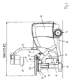
- FIG. 1 shows the medical system in a first embodiment.
- a device carrier 10 carries the entire system.
- the tool carrier 10 has substantially the shape of a horizontal rectangle and is formed by a simple one-piece lightweight steel structure. At its one narrow end, the equipment carrier 10 wheels 12. At the other Schmalende is the equipment rack 10 with feet 14 on the floor.
- a housing 16 which occupies about half of the longitudinal extension of the equipment carrier.
- a device for locating and / or diagnosis (short locating device) of a patient to be treated body area At the front narrow side of the housing 16 is a device for locating and / or diagnosis (short locating device) of a patient to be treated body area, a device for generating and focusing acoustic waves (short therapy device) on this body area to be treated and a device for storage of the treated Patient (short storage facility) arranged.
- the locating device is in the illustrated embodiment, an X-ray locating device, which consists of an X-ray source 18 and an X-ray receiver 20 is made.
- the X-ray source 18 and the X-ray receiver 20 are attached to the two free ends of a C-arm 22.
- the C-arm 22 is pivotally mounted on the housing 16 in its central region about a pivot axis 24.
- the pivot axis 24 extends horizontally and in the direction of the longitudinal axis of the device carrier 10.
- the mode of operation of such an X-ray locating device is known per se in the art.
- an X-ray locating device instead of an X-ray locating device, as shown in the drawing, another known locating device may be used, e.g. an ultrasonic locating device.
- the therapy device has a therapy head 26.
- the therapy head 26 e.g. generated by an electric spark discharge in a liquid acoustic pressure waves, the e.g. be focused by a parabolic reflector as shock waves.
- the therapy head 26 is terminated by a coupling membrane 28 which is applied to the body of the patient to transmit the acoustic shock waves generated in the therapy head 26 into the body of the patient.
- the axis 30 of the X-rays emitted by the X-ray source 18 to the X-ray receiver 20 intersects the pivot axis 24 of the C-arm in an isocenter.
- This isocenter thus remains spatially fixed when the C-arm 22 is pivoted about the pivot axis 24.
- the therapy head 26 is fixed to the housing 16 and oriented so that its central axis intersects the isocenter and the focus of the acoustic shock waves falls into this isocenter.
- the storage of the C-arm 22 with the pivot axis 24 lies in a vertical plane which extends in the longitudinal center axis of the device carrier 10, above the therapy head 26. Therefore the C-arm 22 between the pivot axis 24 and the X-ray source 18 is laterally bent and guided around the therapy head 26 in an arc.
- the housing 16 receives the electrical supply and the electronic control circuit of the locating device and the therapy device. Likewise, a conditioning device for the liquid medium of the therapy head 26 may optionally be arranged in the housing 16. The electronic circuits and controls of the utilities are combined via a common control and data bus system.
- the storage device has a horizontal table 32 on which the patient to be treated is stored.
- the table 32 is height adjustable by means of telescopically extendable vertical lifting columns 34.
- the reclining table 32 is movable toward and away from the therapy device by means of horizontal guides 36.
- vertical horizontal guides 38 serve to move the table 32 transverse to the longitudinal extension of the device carrier 10.
- the height adjustment by means of the lifting columns 34 and the horizontal adjustment in the guides 36 and 38 is preferably carried out via a pneumatic, or hydraulic or electric drive.
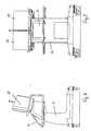
- FIG. 2 is a pneumatic unit 40 for the horizontal transverse displacement in the guides 38 recognizable.
- the lying table 32 has in its central region on the housing 16 facing edge a recess 42, as in FIG. 3 shown.
- the patient is stored on the lying table 32 in such a way that his body area to be treated, for example a body concrement to be destroyed, a tumor, a bone area to be treated or the like, comes to lie on this recess 42.
- the table 32 can be moved with the patient controlled in the three spatial coordinates to the means The locating device localized to be treated body area in the isocenter and thus to position in the focus of the therapy head 26.
- the signals of the locating device for example, the signals of the X-ray receiver 20 are passed to an image processing and displayed in an imaging system, for example on a monitor.
- an observation under different spatial directions is possible in order to determine the spatial position of the body region to be treated.
- FIG. 2 is also shown in dashed lines, as the X-ray locating device is pivoted from the vertical position by 30 ° in order to aim and locate the body region to be treated from two spatial directions.
- the lying surface of the table 32 is shown divided into three surface parts.
- the middle surface portion with the recess 42 is slidably mounted for the positioning of the patient in the guides 36 and 38.
- the two on the device carrier 10 on both sides protruding end portions 44 of the lying surface are each about a horizontal in the longitudinal direction of the device carrier 10 extending axis swung up until they are perpendicular to the top and are thus within the base of the device carrier 10.
- the end portions 44 are also pneumatic units 46. While in the FIGS. 1 . 2 and 3 the end portions 44 are folded down, so that the lying table 32 has a continuous horizontal lying surface, show the FIGS. 4 and 5 the end portions 44 in the raised position.
- the length and the width of the device system correspond to the base area of a standard hospital bed or may be smaller than this base area. Accordingly, in the FIGS. 1 and 3 the total length of the arranged on the equipment rack 10 integrated system with 1920 mm and in FIG. 5 the width of the system with the swung-up end portions 44 with 980 mm.
- the system is mobile.
- a driving device 48 which is attached to the wheels 12 opposite narrow side of the device carrier 10 and the device carrier 10 engages below to raise the device carrier 10, so that the feet 14 free from the floor.
- the driving device 48 engages positively on the underside of the device carrier 10.
- the driver 48 is equipped with wheels 50 and preferably powered by a motor, eg by a battery-powered electric motor.
- a handle 52 serves to guide and maneuver the movable on the wheels 12 of the equipment carrier 10 and the wheels 15 of the driving device 48 system. Due to the above dimensions of the equipment carrier 10 and arranged on the equipment rack integrated system, a method and maneuvering of the system is also possible inside buildings and through door openings.
- the operating device 54 is designed as a self-contained movable unit.
- the operating device 54 has a control panel 56, the bsw. can be realized as a touch screen.
- the control panel 56 contains switching elements for the operation and control of the locating device and the therapy device as well as switching elements for the method of the lying table 32 in the three spatial axes.
- the operating device 54 display devices, such as monitors 58, to represent the captured by the locator images.
- the operating device 54 is connected to the system via cable or via a non-wired signal exchange.
- FIG. 8 shows a further modification of the system, in which also the operating device 54 is arranged on the equipment carrier 10 and integrated into the system.
- the operating device 54 is constructed on the housing 16, resulting in a further space saving and ease of transport.
Landscapes
- Health & Medical Sciences (AREA)
- Surgery (AREA)
- Life Sciences & Earth Sciences (AREA)
- Heart & Thoracic Surgery (AREA)
- Molecular Biology (AREA)
- Vascular Medicine (AREA)
- Engineering & Computer Science (AREA)
- Biomedical Technology (AREA)
- Orthopedic Medicine & Surgery (AREA)
- Medical Informatics (AREA)
- Nuclear Medicine, Radiotherapy & Molecular Imaging (AREA)
- Animal Behavior & Ethology (AREA)
- General Health & Medical Sciences (AREA)
- Public Health (AREA)
- Veterinary Medicine (AREA)
- Accommodation For Nursing Or Treatment Tables (AREA)
- Radiation-Therapy Devices (AREA)
Description
- Die Erfindung betrifft ein medizinisches System gemäß dem Oberbegriff des Anspruchs 1.
- Ein medizinisches System dieser Gattung ist aus der
DE 197 46 956 C2 bekannt. Dieses bekannte System dient zur Behandlung eines Patienten mit fokussierten akustischen Wellen. Der Patient wird auf einer Lagerungseinrichtung in Form eines Tisches gelagert. Der zu behandelnde Körperbereich des Patienten, z. B. ein Konkrement oder eine Gewebepartie wird mittels einer Ortungseinrichtung ermittelt. Eine Therapieeinrichtung erzeugt akustische Wellen, die auf den mittels der Ortungseinrichtung ermittelten Körperbereich fokussiert werden, um dort die gewünschte therapeutische Wirkung zu verursachen, z. B. ein Konkrement oder einen Tumor zu zerstören. - Bei dem bekannten System sind die Ortungseinrichtung und die Therapieeinrichtung jeweils gesonderte Geräte, die mit jeweils einer eigenen Versorgungseinrichtung ausgestattet sind. Die Ortungseinrichtung ist als Röntgengerät mit einem C-Bogen ausgebildet. Damit das System eingesetzt werden kann, werden die Ortungseinrichtung und die Therapieeinrichtung mechanisch gekoppelt und gegenseitig justiert, so das der Fokus der von der Therapieeinrichtung erzeugten akustischen Wellen in das Isozentrum der Röntgen-Ortungseinrichtung fällt.
- Die Ortungseinrichtung und die Therapieeinrichtung sind relativ große und schwere Geräte. Die Kopplung und insbesondere die gegenseitige Justage und elektrische Verbindung der Ortungseinrichtung und der Therapieeinrichtung sind mühsam, zeitaufwendig und müssen durch Fachpersonal durchgeführt werden. Ein Transport des Systems, wozu die einzelnen Komponenten voneinander getrennt werden müssen, wird daher nur in Ausnahmefällen durchgeführt werden.
- Als weiterer Stand der Technik werden die
DE 195 20 748 A1 ,DE 42 32 683 C1 ,DE 197 02829 A1 undDE 44 41 939 A1 genannt. - Der Erfindung liegt die Aufgabe zugrunde, ein medizinisches System der eingangs genannten Gattung zu schaffen, welches in Bezug auf seine räumlichen Einsatzmöglichkeiten flexibler ist.
- Diese Aufgabe wird erfindungsgemäß gelöst durch ein medizinisches System mit den Merkmalen des Anspruchs 1.
- Vorteilhafte Ausführungen der Erfindung sind in den Unteransprüchen angegeben.
- Der wesentliche Gedanke der Erfindung besteht darin, dass die Ortungseinrichtung, die Therapieeinrichtung mit ihren jeweils zugehörigen Versorgungseinrichtungen sowie die Lagerungseinrichtung in einem gemeinsamen Geräteträger angeordnet und montiert sind. Die Länge und die Breite des in den Geräteträger montierten Systems sind höchstens so groß wie die projizierte Grundfläche eines Standart-Krankenhausbettes, d.h. übertreffen diese Grundflächenabmessungen zumindest nicht wesentlich. Die Ortungseinrichtung, die Therapieeinrichtung und die Lagerungseinrichtung sind in dem Geräteträger fest montiert und relativ zueinander justiert. Die sich hieraus ergebende geringe Grundfläche ermöglicht es, das System in vollständig montiertem Zustand zu transportieren und insbesondere auch in die Behandlungsräume einer Klinik oder einer Arztpraxis in montiertem Zustand zu befördern. Dadurch ergibt sich der wesentliche Vorteil, dass das System werkseitig montiert und justiert angeliefert und aufgestellt werden kann, ohne dass am Aufstellungsort umfangreiche Montage- und Justierungsarbeiten erforderlich sind. Weiter kann das System in montiertem Zustand von einem Behandlungsort zu einem anderen Behandlungsort transportiert werden, ohne dass eine Entkopplung der einzelnen Geräte notwendig ist, die wiederum eine Kopplung und Justierung am neuen Aufstellungsort zur Folge hat. Das System kann dadurch in bequemer Weise von einem Raum in einen anderen Raum eines Gebäudes verbracht werden und eignet sich insbesondere auch für den mobilen Einsatz, bei welchem das System unterschiedlichen Nutzern an unterschiedlichen Orten jeweils für eine beschränkte Zeit z.B. angemietet zur Verfügung steht.
- Die Lagerungseinrichtung des erfindungsgemässen medizinischen Systems ist zweckmäßigerweise verstellbar, so dass der auf der Lagerungseinrichtung liegende Patient mit seinem zu behandelnden Körperbereich in den Fokus der Therapieeinrichtung positioniert werden kann. Ist die Lagerungseinrichtung mit einem Liegestuhl ausgebildet, auf welchem der zu behandelnde Patient sitzt, so kann dieser Liegestuhl im Wesentlichen in die Außenabmessungen des Geräteträgers eingefügt werden, so dass die einfache Transportmöglichkeit des Systems durch die Lagerungseinrichtung nicht beeinträchtigt wird. In einer vorteilhaften Ausführung weist die Lagerungseinrichtung einen Liegetisch auf, auf welchem der Patient während der Behandlung ausgestreckt liegt. Damit die Transportmöglichkeiten des Systems nicht behindert werden, ist in dieser Ausführungsform der Liegetisch so ausgebildet, dass er vorzugsweise ohne Zuhilfenahme von Werkzeugen verkleinert werden kann. Hierzu ist die Liegefläche des Liegetisches zweckmäßigerweise unterteilt, wobei die einzelnen Flächenteile zusammengeschoben, zusammengeklappt oder hochgeschwenkt werden können, so dass sie nicht mehr über den Außenumfang des Geräteträgers hinausragen.
Vorzugsweise ist der Liegetisch der Lagerungseinrichtung an einer Schmalseite des Geräteträgers und quer zu dessen Längserstreckung angeordnet. Dadurch ist der Liegetisch von wenigstens drei Seiten frei zugänglich, so dass auch ein gebrechlicher oder behinderter Patient sich einfach auf den Liegetisch begeben kann bzw. von dem Pflegepersonal auf den Liegetisch gelegt werden kann. Außerdem ist der auf dem Liegetisch liegende Patient für den behandelnden Arzt bzw. das behandelnde Personal gut zugänglich. Die Anordnung der Lagerungseinrichtung an einer Endschmalseite des Geräteträgers macht außerdem möglich, dass der Liegetisch mit einem großen vertikalen Hubweg ausgestattet werden kann, wobei insbesondere ein Absenken der Liegefläche des Liegetisches zur Erleichterung des Besteigens des Liegetisches möglich ist. Hierzu kann der Liegetisch beispielsweise soweit gesenkt werden, dass die Liegefläche eine Aufstiegshöhe über dem Fußboden von weniger als 75 cm aufweist. - Um eine möglichst kompakte Anordnung des Systems in dem Geräteträger zu erreichen, sind die Versorgungseinrichtungen für die Therapieeinrichtung ,die Ortungseinrichtung und die Lagerungseinrichtung in einem Endbereich des Geräteträgers angeordnet und die Ortungseinrichtung und die Therapieeinrichtung sind an der schmalen Stirnseite der Versorgungseinrichtung angebracht, die der Lagerungseinrichtung zugewandt ist. Die Ortungseinrichtung ist i.d.R. schwenkbar gelagert, um den zu behandelnden Körperbereich räumlich zu lokalisieren und in dem Isozentrum der Ortungseinrichtung zu positionieren. Ist die Ortungseinrichtung an der schmalen Stirnseite der Versorgungseinrichtung angeordnet, so verläuft die Schwenkachse der Ortungseinrichtung vorzugsweise horizontal in Längsrichtung des Geräteträgers. Ist die Ortungseinrichtung insbesondere als Röntgeneinrichtung mit einer Röntgenstrahlquelle und einem Röntgenstrahlempfänger an einem schwenkbaren C-Bogen ausgebildet, so ist dieser C-Bogen vorzugsweise seitlich abgekröpft. Dadurch können die Schwenkachse des C-Bogens und die Stoßwellenquelle der Therapieeinrichtung in einer vertikalen Ebene übereinander liegen und der C-Bogen wird seitlich um die Stoßwellenquelle herumgeführt.
- Die elektrische Energieversorgung und Steuerung der Ortungseinrichtung, der Therapieeinrichtung und der Lagerungseinrichtung sind in dem Geräteträger in einer kompakten Einheit integriert. Dies hat den Vorteil, dass die benötigten elektrischen Komponenten wesentlich reduziert werden können, dass eine gemeinsame Verkabelung installiert werden kann und eine elektrische Abstimmung von Ortungseinrichtung, Therapieeinrichtung und Lagerungseinrichtung und deren Versorgungseinrichtungen nicht notwendig ist. Weiter kann die gesamte Steuerung der Ortungseinrichtung, der Therapieeinrichtung und der Lagerungseinrichtung über ein Steuer- und Datenbussystem erfolgen. Das Steuer- und Datenbussystem kann über eine einzige Schnittstelle mit einer Bedieneinrichtung verbunden sein, über welche die Ortungseinrichtung, die Therapieeinrichtung und die Lagerungseinrichtung gesteuert und betätigt werden. Die Bedieneinrichtung kann als eine separate Einheit ausgebildet sein, welche leitungsgebunden oder nicht leitungsgebunden an das Steuer- und Datenbussystem angeschlossen ist. Die Bedieneinrichtung kann auch in das System integriert in dem Geräteträger angeordnet sein.
- Die Integration der gesamten elektrischen und elektronischen Komponenten und insbesondere deren Installation in einem Steuer- und Datenbussystem ermöglichen weiter eine Ferndiagnose und/oder -wartung des gesamten Systems, z.B. über ein GSM-Modem oder ein Telefonmodem. Dadurch ist Wartung und Service des Systems zeit- und kostensparend möglich.
- Die Ortungseinrichtung ist zweckmäßig mit einer bildgebenden Einrichtung ausgestattet, die vorzugsweise mit einem in die Bedieneinrichtung integrierten Monitor versehen ist, so dass der zu behandelnde Körperbereich des Patienten und dessen Positionierung von dem Arzt beobachtet und begutachtet werden können. Der Patient kann je nach dem zu behandelnden Körperbereich unterschiedlich auf der Lagerungseinrichtung gelagert werden. Insbesondere ist alternativ eine Rücken- oder Bauchlagerung möglich und ebenso ist eine Vertauschung von Kopfund Fußlage des Patienten z.B. zur Ortung und Behandlung der rechten oder linken Niere möglich. In einer vorteilhaften Ausführung ist die bildverarbeitende Einrichtung so ausgelegt, dass durch Eingabe der Lage des Patienten Spiegelungen der Bildinformationen in der Weise stattfinden, dass auf dem Monitor der Bedieneinrichtung stets die Abbildung in derselben Patientenlage erfolgt, z.B. in der Weise, dass der Körper des Patienten von vorn gesehen wird und der Kopf des Patienten sich im Bild oben befindet. Die die unterschiedlichen Positionen des Patienten auf der Lagerungseinrichtung kompensierenden Spiegelungen können außerdem auch auf die Steuerung der Lagerungseinrichtung durch die Bedieneinrichtung übertragen werden. Dadurch kann der Arzt an der Bedieneinrichtung die Positionierung nach dem ggf. gespiegelten Monitorbild durchführen, wobei die Lagerungseinrichtung entsprechend der tatsächlichen Position des Patienten gesteuert bewegt wird.
- Das gesamte medizinische System kann mit dem Geräteträger einfach transportiert und stationär aufgestellt werden. Ist eine Veränderung des Aufstellungsortes beabsichtigt, so ist vorzugsweise der Geräteträger verfahrbar ausgebildet. Der Geräteträger weist hierzu an seinem einen Ende Laufrollen oder -räder auf. Mit dem anderen Ende sitzt der Geräteträger auf dem Fußboden auf, so dass das System stabil ortsfest steht. Für den Transport wird ein Fahrgerät verwendet, welches an dem den Laufrollen oder -rädern entgegengesetzten Ende des Geräteträgers angreift, um den Geräteträger mit dem integrierten System insgesamt verfahrbar zu machen. Das Fahrgerät untergreift dabei vorzugsweise formschlüssig den Geräteträger, um diesen vom Fußboden abzuheben. Das Fahrgerät ist steuerbar, um ein leichtes Manövrieren beim Verfahren zu ermöglichen. Zweckmäßigerweise kann das Fahrgerät auch motorisch angetrieben sein, z.B. mittels eines akkugespeisten Elektromotors.
- Im Folgenden wird die Erfindung anhand von in der Zeichnung dargestellten Ausführungsbeispielen näher erläutert. Es zeigen
- Figur 1
- eine Seitenansicht des medizinischen Systems in einer ersten Ausführung,
- Figur 2
- eine Stirnansicht des Systems der
Figur 1 , - Figur 3
- eine Draufsicht auf das System in der zweiten Ausführung,
- Figur 4
- eine Seitenansicht des Systems in der zweiten Ausführung während des Transports,
- Figur 5
- eine Stirnansicht der
Figur 4 , - Figur 6
- eine Seitenansicht der Bedieneinrichtung,
- Figur 7
- eine Stirnansicht der Bedieneinrichtung und
- Figur 8
- eine Seitenansicht des Systems in einer dritten Ausführung mit integrierter Bedieneinrichtung.
-
Figur 1 zeigt das medizinische System in einer ersten Ausführung. - Ein Geräteträger 10 trägt das gesamte System. Der Geräteträger 10 hat im Wesentlichen die Form eines horizontalen Rechtecks und wird durch eine einfache einteilige leichte Stahlbaustruktur gebildet. An seinem einen Schmalende weist der Geräteträger 10 Laufräder 12 auf. An dem anderen Schmalende steht der Geräteträger 10 mit Füßen 14 auf dem Fußboden auf.
- Auf dem Geräteträger 10 sitzt ein Gehäuse 16, welches etwa die Hälfte der Längserstreckung des Geräteträgers einnimmt. An der Stirnschmalseite des Gehäuses 16 ist eine Einrichtung zur Ortung und/oder Diagnose (kurz Ortungseinrichtung) eines zur behandelnden Körperbereichs eines Patienten, eine Einrichtung zur Erzeugung und Fokussierung akustischer Wellen (Kurztherapieeinrichtung) auf diesen zu behandelnden Körperbereich und eine Einrichtung zur Lagerung des zu behandelnden Patienten (kurz Lagerungseinrichtung) angeordnet.
- Die Ortungseinrichtung ist im dargestellten Ausführungsbeispiel eine Röntgen-Ortungseinrichtung, die aus einer Röntgenstrahlquelle 18 und einem Röntgenstrahlempfänger 20 besteht. Die Röntgenstrahlquelle 18 und der Röntgenstrahlempfänger 20 sind an den beiden freien Enden eines C-Bogens 22 angebracht. Der C-Bogen 22 ist in seinem mittleren Bereich um eine Schwenkachse 24 schwenkbar an dem Gehäuse 16 gelagert. Die Schwenkachse 24 verläuft horizontal und in Richtung der Längsachse des Geräteträgers 10. Die Funktionsweise einer solchen Röntgenortungseinrichtung ist an sich bekannter Stand der Technik.
- Anstelle einer Röntgenortungseinrichtung, wie sie in der Zeichnung dargestellt ist, kann auch eine andere an sich bekannte Ortungseinrichtung verwendet werden, z.B. eine Ultraschall-Ortungseinrichtung.
- Die Therapieeinrichtung weist einen Therapiekopf 26 auf. In dem Therapiekopf 26 werden z.B. durch eine elektrische Funkenentladung in einer Flüssigkeit akustische Druckwellen erzeugt, die z.B. durch einen Parabolreflektor als Stoßwellen fokussiert werden. Der Therapiekopf 26 ist durch eine Koppelmembran 28 abgeschlossen, die an den Körper des Patienten angelegt wird, um die in dem Therapiekopf 26 erzeugten akustischen Stoßwellen in den Körper des Patienten zu übertragen.
- Die Achse 30 der von der Röntgenstrahlquelle 18 zu dem Röntgenstrahlempfänger 20 ausgesandten Röntgenstrahlen schneidet die Schwenkachse 24 des C-Bogens in einem Isozentrum. Dieses Isozentrum bleibt somit räumlich fest, wenn der C-Bogen 22 um die Schwenkachse 24 geschwenkt wird. Der Therapiekopf 26 ist an dem Gehäuse 16 fest angeordnet und so ausgerichtet, dass seine Mittelachse das Isozentrum schneidet und der Fokus der akustischen Stoßwellen in dieses Isozentrum fällt.
- Die Lagerung des C-Bogens 22 mit der Schwenkachse 24 liegt in einer vertikalen Ebene, die in der Längsmittelachse des Geräteträgers 10 verläuft, oberhalb des Therapiekopfes 26. Deshalb ist der C-Bogen 22 zwischen der Schenkachse 24 und der Röntgenstrahlquelle 18 seitlich ausgekröpft und in einem Bogen um den Therapiekopf 26 herumgeführt.
- Das Gehäuse 16 nimmt die elektrische Versorgung und die elektronische Steuerschaltung der Ortungseinrichtung und der Therapieeinrichtung auf. Ebenso kann in dem Gehäuse 16 ggf. eine Aufbereitungseinrichtung für das flüssige Medium des Therapiekopfes 26 angeordnet sein. Die elektronischen Schaltungen und Steuerungen der Versorgungseinrichtungen sind über ein gemeinsames Steuer und Datenbus-System zusammengefasst.
- Die Lagerungseinrichtung weist einen horizontalen Liegetisch 32 auf, auf welchem der zu behandelnde Patient gelagert wird. Der Liegetisch 32 ist mittels teleskopisch ausfahrbarer vertikaler Hubsäulen 34 höhenverstellbar. Außerdem ist der Liegetisch 32 mittels horizontaler Führungen 36 gegen die Therapieeinrichtung hin und von dieser weg bewegbar. Weitere zu den Führungen 36 senkrechte horizontale Führungen 38 dienen dazu, den Liegetisch 32 quer zur Längserstreckung des Geräteträgers 10 zu verschieben. Die Höhenverstellung mittels der Hubsäulen 34 und die Horizontalverstellung in den Führungen 36 und 38 erfolgt vorzugsweise über einen pneumatischen, oder hydraulischen oder elektrischen Antrieb.
- In
Figur 2 ist ein pneumatisches Aggregat 40 für die horizontale Querverschiebung in den Führungen 38 erkennbar.
Der Liegetisch 32 weist in seinem mittleren Bereich an der dem Gehäuse 16 zugewandten Kante eine Aussparung 42 auf, wie inFigur 3 dargestellt. Der Patient wird auf dem Liegetisch 32 so gelagert, dass sein zu behandelnder Körperbereich z.B. ein zu zerstörendes Körperkonkrement, ein Tumor, ein zu behandelnder Knochenbereich oder dergleichen auf dieser Aussparung 42 zu liegen kommt. Mittels der Hubsäulen 34 und der Führungen 36 und 38 kann der Liegetisch 32 mit dem Patienten in den drei räumlichen Koordinaten gesteuert verfahren werden, um den mittels der Ortungseinrichtung lokalisierten zu behandelnden Körperbereich in dem Isozentrum und damit in dem Fokus des Therapiekopfes 26 zu positionieren. Hierzu werden die Signale der Ortungseinrichtung, z.B. die Signale des Röntgenstrahlempfängers 20 zu einer Bildverarbeitung geleitet und in einem bildgebenden System, z.B. auf einem Monitor dargestellt. Durch Schwenken des C-Bogens 22 ist eine Beobachtung unter unterschiedlichen räumlichen Richtungen möglich, um die räumliche Lage des zu behandelnden Körperbereichs zu ermitteln. - In
Figur 2 ist auch gestrichelt dargestellt, wie die Röntgenortungseinrichtung aus der vertikalen Position um 30° geschwenkt wird, um den zu behandelnden Körperbereich aus zwei räumlichen Richtungen anzupeilen und zu lokalisieren. - In den
Figuren 2 und3 ist die Liegefläche des Liegetisches 32 in drei Flächenteile unterteilt dargestellt. Der mittlere Flächenteil mit der Aussparung 42 ist für die Positionierung des Patienten in den Führungen 36 und 38 verschiebbar gelagert. Die beiden über den Geräteträger 10 beidseitig hinausragenden Endteile 44 der Liegefläche sind jeweils um eine horizontale in Längsrichtung des Geräteträgers 10 verlaufende Achse hochschwenkbar, bis sie senkrecht nach oben stehen und sich somit innerhalb der Grundfläche des Geräteträgers 10 befinden. Zum Hochschwenken der Endteile 44 dienen ebenfalls pneumatische Aggregate 46. Während in denFiguren 1 ,2 und3 die Endteile 44 nach unten geklappt sind, so dass der Liegetisch 32 eine durchgehende horizontale Liegefläche aufweist, zeigen dieFiguren 4 und5 die Endteile 44 in der hochgeschwenkten Stellung. - Die Länge und die Breite des Gerätesystems entsprechen der Grundfläche eines Standard-Krankenhausbettes oder sind ggf. auch kleiner als diese Grundfläche. Dementsprechend ist in den
Figuren 1 und3 die Gesamtlänge des auf dem Geräteträger 10 angeordneten integrierten Systems mit 1920 mm angegeben und inFigur 5 die Breite des Systems mit den hochgeschwenkten Endteilen 44 mit 980 mm. - In der in der Zeichnung dargestellten Ausführung, in welcher der Geräteträger 10 mit Laufrädern 12 versehen ist, ist das System fahrbar. Wie in den
Figuren 4 und5 dargestellt ist, kann hierzu ein Fahrgerät 48 verwendet werden, welches an der den Laufrädern 12 entgegengesetzten Schmalseite des Geräteträgers 10 angesetzt wird und den Geräteträger 10 untergreift, um den Geräteträger 10 anzuheben, so dass die Füße 14 vom Fußboden freikommen. Vorzugsweise greift das Fahrgerät 48 dabei formschlüssig an der Unterseite des Geräteträgers 10 an. Das Fahrgerät 48 ist mit Laufrädern 50 ausgestattet und vorzugsweise motorisch angetrieben, z.B. durch einen akkugespeisten Elektromotor. Ein Handgriff 52 dient zum Führen und Manövrieren des auf den Laufrädern 12 des Geräteträgers 10 und den Laufrädern 15 des Fahrgeräts 48 verfahrbaren Systems. Aufgrund der oben genannten Abmessungen des Geräteträgers 10 und des auf dem Geräteträger angeordneten integrierten System ist ein Verfahren und Manövrieren des Systems auch im Inneren von Gebäuden und durch Türöffnungen möglich. - In den Ausführungen der
Figuren 1 bis 5 wird das System mit einer separaten Bedieneinrichtung 54 betrieben, die in denFiguren 6 und 7 dargestellt ist. Die Bedieneinrichtung 54 ist als selbstständige verfahrbare Einheit ausgebildet. Die Bedieneinrichtung 54 weist ein Bedienfeld 56 auf, das bsw. als Touch-Screen realisiert sein kann. Das Bedienfeld 56 enthält Schaltelemente für den Betrieb und die Steuerung der Ortungseinrichtung und der Therapieeinrichtung sowie Schaltelemente für das Verfahren des Liegetisches 32 in den drei räumlichen Achsen. Weiter weist die Bedienungseinrichtung 54 Anzeigeeinrichtungen, z.B. Monitore 58 auf, um die von der Ortungseinrichtung aufgenommenen Bilder darzustellen. Die Bedieneinrichtung 54 ist mit dem System über Kabel oder über einen nicht leitungsgebundenen Signalaustausch verbunden. -
Figur 8 zeigt eine weitere Abwandlung des Systems, bei welcher auch die Bedieneinrichtung 54 auf dem Geräteträger 10 angeordnet und in das System integriert ist. Hierzu ist die Bedieneinrichtung 54 auf dem Gehäuse 16 aufgebaut, wodurch sich eine weitere Platzeinsparung und eine Erleichterung des Transports ergibt. - Bezugszeichenliste
- 10
- Geräteträger
- 12
- Laufräder
- 14
- Füße
- 16
- Gehäuse
- 18
- Röntgenstrahlquelle
- 20
- Röntgenstrahlempfänger
- 22
- C-Bogen
- 24
- Schwenkachse
- 26
- Therapiekopf
- 28
- Koppelmembran
- 30
- Achse für Röntgenstrahlen
- 32
- Liegetisch
- 34
- Hubsäulen
- 36
- Führungen
- 38
- Führungen
- 40
- Pneumatisches Aggregat
- 42
- Aussparung
- 44
- Endteile
- 46
- Pneumatische Aggregate
- 48
- Fahrgerät
- 50
- Laufräder
- 52
- Handgriff
- 54
- Bedieneinrichtung
- 56
- Bedienfeld
- 58
- Monitore
Claims (13)
- Medizinisches System, mit einer Ortungseinrichtung zur Ortung und/oder Diagnose eines zu behandelnden Körperbereichs eines Patienten, mit einer Therapieeinrichtung zur Erzeugung von akustischen Wellen und zur Fokussierung dieser Wellen in den zu behandelnden Körperbereich, mit einer Lagerungseinrichtung zur Lagerung des zu behandelnden Patienten und mit Versorgungseinrichtungen zur Energieversorgung und Steuerung der Ortungseinrichtung, der Therapieeinrichtung und der Lagerungseinrichtung, wobei die Ortungseinrichtung (18, 20, 22), die Therapieeinrichtung (26), die Lagerungseinrichtung (32), und deren Versorgungseinrichtungen in einem gemeinsamen Geräteträger (10) angeordnet sind und wobei die Ortungseinrichtung (18, 20) und die Therapieeinrichtung (26) in diesem Geräteträger (10) relativ zueinander justiert sind, dadurch gekennzeichnet, dass die projizierte Grundfläche der Ortungseinrichtung (18, 20, 22), der Therapieeinrichtung (26), der Lagerungseinrichtung (32), und deren Versorgungseinrichtungen eine Länge von 1920 mm und eine Breite von 980 mm aufweist, wobei der Geräteträger (10) an einem Ende Laufräder (12) aufweist und an seinem entgegengesetzten Ende mit Füßen (14) auf dem Fußboden aufsteht und dass ein Fahrgerät (48) vorgesehen ist, mit welchem dieses andere Ende des Geräteträgers (10) angehoben werden kann, um den Geräteträger verfahrbar zu machen.
- Medizinisches System nach Anspruch 1,
dadurch gekennzeichnet, dass die Lagerungseinrichtung (32), in Bezug auf die Ortungseinrichtung (18, 20) und die Therapieeinrichtung (26) räumlich positionierbar ist. - Medizinisches System nach den Ansprüchen 1 und 2,
dadurch gekennzeichnet, dass die Lagerungseinrichtung einen Liegetisch (32) aufweist, der in einer Betriebsstellung zur Lagerung eines Patienten über den Geräteträger (10) hinausragt, und der in eine Transportstellung gebracht werden kann, in welcher er sich innerhalb des Umfangs des Geräteträgers (10) befindet. - Medizinisches System nach einem der vorhergehenden Ansprüche,
dadurch gekennzeichnet, dass die Versorgungseinrichtungen der Ortungseinrichtung, der Therapieeinrichtung und der Lagerungseinrichtung in einem gemeinsamen Gehäuse (16) integriert und gemeinsam elektrisch verschaltet sind. - Medizinisches System nach Anspruch 4,
dadurch gekennzeichnet, dass die Steuerung und Überwachung der Ortungseinrichtung, der Therapieeinrichtung und der Lagerungseinrichtung über ein Steuer- und Datenbussystem erfolgt. - Medizinisches System nach Anspruch 4,
dadurch gekennzeichnet, dass die Ortungseinrichtung, die Therapieeinrichtung und die Lagerungseinrichtung über eine gemeinsame Bedieneinrichtung (54) überwacht und gesteuert werden. - Medizinisches System nach Anspruch 4,
dadurch gekennzeichnet, dass die Bedieneinrichtung (54) eine bildgebende Einrichtung (58) aufweist zur Darstellung der von der Ortungseinrichtung empfangenen Bildsignale. - Medizinisches System nach Anspruch 7,
dadurch gekennzeichnet, dass die Bildsignale der Ortungseinrichtung zu der bildgebenden Einrichtung (58) über eine Bildverarbeitung geführt werden, die entsprechend einer eingebbaren Patientenposition umschaltbar eine oder mehrere Bildspiegelungen durchführt. - Medizinisches System nach Anspruch 5,
dadurch gekennzeichnet, dass das Steuer und Datenbussystem an eine Ferndiagnose und/oder - Wartung anschließbar ist. - Medizinisches System nach einem der vorhergehenden Ansprüche,
dadurch gekennzeichnet, dass die Versorgungseinrichtungen in einem Gehäuse (16) integriert sind, dass die Ortungseinrichtung (18, 20) und die Therapieeinrichtung (26) an einer Stirnseite des Gehäuses (16) angeordnet sind und dass die Lagerungseinrichtung (32) vor dieser Stirnseite angeordnet ist. - Medizinisches System nach Anspruch 10,
dadurch gekennzeichnet, dass die Ortungseinrichtung eine Röntgenortungseinrichtung mit einer Röntgenstrahlquelle (18) und einem Röntgenstrahlempfänger (20) ist, die an einem C-Bogen (22) angeordnet sind, dass der C-Bogen in einer vertikalen Längsmittelebene oberhalb des Therapiekopfes (26) der Therapieeinrichtung schwenkbar gelagert ist und dass der C-Bogen (22) unterhalb seiner Schwenklagerachse bogenförmig ausgekröpft um den Therapiekopf (26) herumgeführt ist. - Medizinisches System nach Anspruch 11,
dadurch gekennzeichnet, dass der C-Bogen (22) der Ortungseinrichtung in der Höhe reduzierbar ausgeführt ist. - Medizinisches System nach Anspruch 12,
dadurch gekennzeichnet, dass der C-Bogen (22) der Ortungseinrichtung vorzugsweise klappbar ausgeführt ist.
Applications Claiming Priority (2)
| Application Number | Priority Date | Filing Date | Title |
|---|---|---|---|
| DE2002107385 DE10207385A1 (de) | 2002-02-21 | 2002-02-21 | Medizinisches System |
| DE10207385 | 2002-02-21 |
Publications (3)
| Publication Number | Publication Date |
|---|---|
| EP1338249A2 EP1338249A2 (de) | 2003-08-27 |
| EP1338249A3 EP1338249A3 (de) | 2004-01-02 |
| EP1338249B1 true EP1338249B1 (de) | 2010-06-02 |
Family
ID=27635223
Family Applications (1)
| Application Number | Title | Priority Date | Filing Date |
|---|---|---|---|
| EP20030003578 Expired - Lifetime EP1338249B1 (de) | 2002-02-21 | 2003-02-17 | Medizinisches System |
Country Status (2)
| Country | Link |
|---|---|
| EP (1) | EP1338249B1 (de) |
| DE (2) | DE10207385A1 (de) |
Families Citing this family (2)
| Publication number | Priority date | Publication date | Assignee | Title |
|---|---|---|---|---|
| DE102004002564B4 (de) * | 2004-01-17 | 2010-04-01 | Ziehm Imaging Gmbh | Mobile chirurgische Röntgendiagnostikeinrichtung |
| US20090060821A1 (en) | 2007-08-27 | 2009-03-05 | Andreas Menzel | Method for manufacturing silicone wafers |
Family Cites Families (7)
| Publication number | Priority date | Publication date | Assignee | Title |
|---|---|---|---|---|
| EP0405282A1 (de) * | 1989-06-30 | 1991-01-02 | Siemens Aktiengesellschaft | Gerät zur Behandlung eines Lebewesens mit fukussierten Stosswellen |
| DE4232683C1 (de) * | 1992-09-29 | 1994-04-28 | Siemens Ag | Therapieeinrichtung zur Behandlung mit fokussierten akustischen Wellen |
| US5572566A (en) * | 1993-11-30 | 1996-11-05 | J. Morita Manufacturing Corporation | X-ray imaging apparatus and X-ray generation detector for activating the same |
| DE19520748C2 (de) * | 1995-06-07 | 1999-09-02 | Siemens Ag | Therapiegerät mit einer Strahlungsquelle |
| DE19702829A1 (de) * | 1997-01-27 | 1998-07-30 | Siemens Ag | Medizinisches Gerät |
| DE19718511C5 (de) * | 1997-05-02 | 2010-10-21 | Sanuwave, Inc., | Gerät zur Applikation von akustischen Stoßwellen |
| DE19746956C2 (de) * | 1997-10-23 | 2000-05-11 | Siemens Ag | Medizinisches System aufweisend ein Röntgengerät und ein Therapiegerät mit einer Quelle fokussierter akustischer Wellen |
-
2002
- 2002-02-21 DE DE2002107385 patent/DE10207385A1/de not_active Ceased
-
2003
- 2003-02-17 EP EP20030003578 patent/EP1338249B1/de not_active Expired - Lifetime
- 2003-02-17 DE DE50312753T patent/DE50312753D1/de not_active Expired - Lifetime
Also Published As
| Publication number | Publication date |
|---|---|
| EP1338249A3 (de) | 2004-01-02 |
| EP1338249A2 (de) | 2003-08-27 |
| DE50312753D1 (de) | 2010-07-15 |
| DE10207385A1 (de) | 2003-09-25 |
Similar Documents
| Publication | Publication Date | Title |
|---|---|---|
| EP1878412B1 (de) | Ophthalmochirurgischer Arbeitsplatz | |
| DE19520748C2 (de) | Therapiegerät mit einer Strahlungsquelle | |
| EP0396866B1 (de) | Patientenliege | |
| DE19920008B4 (de) | Operations-Diagnose-Einrichtung mit einer Lagerungsvorrichtung für ein Behandlungs- und/oder Untersucherungsobjekt | |
| DE69727675T2 (de) | Excimerlasersystem zur augenchirurgie | |
| DE19807243C2 (de) | Medizinischer Arbeitsplatz | |
| EP1370178B1 (de) | Medizinische untersuchungs- und/oder behandlungseinrichtung mit einem transportwagen für eine patientenliege und transportwagen | |
| DE60303641T2 (de) | Anordnung zur Strahlentherapie | |
| DE3714397C2 (de) | ||
| DE69725987T2 (de) | Medizinisches gerät mit patiententisch und hebevorrichtung in kompakter und steifer bauart | |
| DE10211081A1 (de) | System zur medizinischen Notversorgung und -überwachung eines Patienten | |
| EP0405282A1 (de) | Gerät zur Behandlung eines Lebewesens mit fukussierten Stosswellen | |
| WO2006003143A1 (de) | Vorrichtung zum platzieren eines patienten | |
| DE69821368T2 (de) | Röntgenstrahldurchlässige verlängerungstischanordnung | |
| CH695538A5 (de) | Medizinische Vorrichtung. | |
| DE102009048361A1 (de) | Medizinische Therapieeinrichtung | |
| EP0264738B1 (de) | Lithotripsie-Arbeitsplatz | |
| DE4216983C2 (de) | Einrichtung für die minimal invasive Therapie und Mikrotherapie | |
| EP0255645A1 (de) | Patientenlagerungstisch | |
| EP1289423B1 (de) | Operations-diagnose-einrichtung mit einer lagerungsvorrichtung für ein behandlungs- und/oder untersuchungsobjekt | |
| EP1720467A1 (de) | Anlage zur bildgestützten stosswellenbehandlung | |
| DE112013006858B4 (de) | Steinentfernende körperexterne Vorrichtung | |
| DE4341324A1 (de) | Medizinische Anlage mit Mitteln zum Erfassen einer physiologischen Funktion | |
| DE4232683C1 (de) | Therapieeinrichtung zur Behandlung mit fokussierten akustischen Wellen | |
| EP2515999A1 (de) | Vorrichtung zur behandlung mit magnetischen feldern |
Legal Events
| Date | Code | Title | Description |
|---|---|---|---|
| PUAI | Public reference made under article 153(3) epc to a published international application that has entered the european phase |
Free format text: ORIGINAL CODE: 0009012 |
|
| AK | Designated contracting states |
Designated state(s): AT BE BG CH CY CZ DE DK EE ES FI FR GB GR HU IE IT LI LU MC NL PT SE SI SK TR |
|
| AX | Request for extension of the european patent |
Extension state: AL LT LV MK RO |
|
| PUAL | Search report despatched |
Free format text: ORIGINAL CODE: 0009013 |
|
| 17P | Request for examination filed |
Effective date: 20031016 |
|
| AK | Designated contracting states |
Kind code of ref document: A3 Designated state(s): AT BE BG CH CY CZ DE DK EE ES FI FR GB GR HU IE IT LI LU MC NL PT SE SI SK TR |
|
| AX | Request for extension of the european patent |
Extension state: AL LT LV MK RO |
|
| AKX | Designation fees paid |
Designated state(s): CH DE FR IT LI TR |
|
| 17Q | First examination report despatched |
Effective date: 20041109 |
|
| 19U | Interruption of proceedings before grant |
Effective date: 20050112 |
|
| 19W | Proceedings resumed before grant after interruption of proceedings |
Effective date: 20060201 |
|
| RAP1 | Party data changed (applicant data changed or rights of an application transferred) |
Owner name: HEALTHTRONICS INC. |
|
| GRAP | Despatch of communication of intention to grant a patent |
Free format text: ORIGINAL CODE: EPIDOSNIGR1 |
|
| GRAC | Information related to communication of intention to grant a patent modified |
Free format text: ORIGINAL CODE: EPIDOSCIGR1 |
|
| GRAS | Grant fee paid |
Free format text: ORIGINAL CODE: EPIDOSNIGR3 |
|
| GRAA | (expected) grant |
Free format text: ORIGINAL CODE: 0009210 |
|
| AK | Designated contracting states |
Kind code of ref document: B1 Designated state(s): CH DE FR IT LI TR |
|
| REG | Reference to a national code |
Ref country code: CH Ref legal event code: EP |
|
| REF | Corresponds to: |
Ref document number: 50312753 Country of ref document: DE Date of ref document: 20100715 Kind code of ref document: P |
|
| REG | Reference to a national code |
Ref country code: CH Ref legal event code: NV Representative=s name: R. A. EGLI & CO. PATENTANWAELTE |
|
| PLBE | No opposition filed within time limit |
Free format text: ORIGINAL CODE: 0009261 |
|
| STAA | Information on the status of an ep patent application or granted ep patent |
Free format text: STATUS: NO OPPOSITION FILED WITHIN TIME LIMIT |
|
| 26N | No opposition filed |
Effective date: 20110303 |
|
| REG | Reference to a national code |
Ref country code: DE Ref legal event code: R097 Ref document number: 50312753 Country of ref document: DE Effective date: 20110302 |
|
| PGFP | Annual fee paid to national office [announced via postgrant information from national office to epo] |
Ref country code: TR Payment date: 20140130 Year of fee payment: 12 |
|
| REG | Reference to a national code |
Ref country code: FR Ref legal event code: PLFP Year of fee payment: 14 |
|
| REG | Reference to a national code |
Ref country code: FR Ref legal event code: PLFP Year of fee payment: 15 |
|
| PG25 | Lapsed in a contracting state [announced via postgrant information from national office to epo] |
Ref country code: TR Free format text: LAPSE BECAUSE OF NON-PAYMENT OF DUE FEES Effective date: 20150217 |
|
| REG | Reference to a national code |
Ref country code: FR Ref legal event code: PLFP Year of fee payment: 16 |
|
| PGFP | Annual fee paid to national office [announced via postgrant information from national office to epo] |
Ref country code: DE Payment date: 20220225 Year of fee payment: 20 Ref country code: CH Payment date: 20220302 Year of fee payment: 20 |
|
| PGFP | Annual fee paid to national office [announced via postgrant information from national office to epo] |
Ref country code: IT Payment date: 20220222 Year of fee payment: 20 Ref country code: FR Payment date: 20220223 Year of fee payment: 20 |
|
| REG | Reference to a national code |
Ref country code: DE Ref legal event code: R071 Ref document number: 50312753 Country of ref document: DE |
|
| REG | Reference to a national code |
Ref country code: CH Ref legal event code: PL |