EP1336539A1 - seat belt system for vehicles and vehicle provided therewith - Google Patents
seat belt system for vehicles and vehicle provided therewith Download PDFInfo
- Publication number
- EP1336539A1 EP1336539A1 EP03003581A EP03003581A EP1336539A1 EP 1336539 A1 EP1336539 A1 EP 1336539A1 EP 03003581 A EP03003581 A EP 03003581A EP 03003581 A EP03003581 A EP 03003581A EP 1336539 A1 EP1336539 A1 EP 1336539A1
- Authority
- EP
- European Patent Office
- Prior art keywords
- seat
- seat belt
- anchor
- door
- rail member
- Prior art date
- Legal status (The legal status is an assumption and is not a legal conclusion. Google has not performed a legal analysis and makes no representation as to the accuracy of the status listed.)
- Granted
Links
- 230000000452 restraining effect Effects 0.000 claims abstract description 8
- 238000001514 detection method Methods 0.000 abstract description 11
- 238000010276 construction Methods 0.000 description 9
- 238000005452 bending Methods 0.000 description 3
- 230000002452 interceptive effect Effects 0.000 description 3
- 230000009286 beneficial effect Effects 0.000 description 1
- 230000001419 dependent effect Effects 0.000 description 1
- 239000000088 plastic resin Substances 0.000 description 1
- 238000009751 slip forming Methods 0.000 description 1
- 210000005182 tip of the tongue Anatomy 0.000 description 1
Images





Classifications
-
- B—PERFORMING OPERATIONS; TRANSPORTING
- B60—VEHICLES IN GENERAL
- B60R—VEHICLES, VEHICLE FITTINGS, OR VEHICLE PARTS, NOT OTHERWISE PROVIDED FOR
- B60R21/00—Arrangements or fittings on vehicles for protecting or preventing injuries to occupants or pedestrians in case of accidents or other traffic risks
- B60R21/01—Electrical circuits for triggering passive safety arrangements, e.g. airbags, safety belt tighteners, in case of vehicle accidents or impending vehicle accidents
- B60R21/015—Electrical circuits for triggering passive safety arrangements, e.g. airbags, safety belt tighteners, in case of vehicle accidents or impending vehicle accidents including means for detecting the presence or position of passengers, passenger seats or child seats, and the related safety parameters therefor, e.g. speed or timing of airbag inflation in relation to occupant position or seat belt use
- B60R21/01512—Passenger detection systems
- B60R21/01516—Passenger detection systems using force or pressure sensing means
-
- B—PERFORMING OPERATIONS; TRANSPORTING
- B60—VEHICLES IN GENERAL
- B60R—VEHICLES, VEHICLE FITTINGS, OR VEHICLE PARTS, NOT OTHERWISE PROVIDED FOR
- B60R22/00—Safety belts or body harnesses in vehicles
- B60R22/18—Anchoring devices
- B60R22/22—Anchoring devices secured to the vehicle floor
-
- B—PERFORMING OPERATIONS; TRANSPORTING
- B60—VEHICLES IN GENERAL
- B60R—VEHICLES, VEHICLE FITTINGS, OR VEHICLE PARTS, NOT OTHERWISE PROVIDED FOR
- B60R22/00—Safety belts or body harnesses in vehicles
- B60R22/18—Anchoring devices
- B60R22/24—Anchoring devices secured to the side, door, or roof of the vehicle
-
- B—PERFORMING OPERATIONS; TRANSPORTING
- B60—VEHICLES IN GENERAL
- B60R—VEHICLES, VEHICLE FITTINGS, OR VEHICLE PARTS, NOT OTHERWISE PROVIDED FOR
- B60R22/00—Safety belts or body harnesses in vehicles
- B60R22/18—Anchoring devices
- B60R22/20—Anchoring devices adjustable in position, e.g. in height
- B60R2022/207—Horizontally or transversally adjustable
Definitions
- the present invention relates to a seat belt system, more particularly, to a seat belt system for a vehicle and to a vehicle provided therewith, which has a double door structure, in which a front door is supported to a vehicular body at its leading edge via a hinge and a rear door is supported to the vehicular body at its trailing edge via a hinge so that both the doors are opened and closed, for example.
- a double door structure is well known as disclosed in Japanese Unexamined Patent Publication No. H8-142680.
- the conventional structure includes a lock pillar extending vertically in the middle portion of a rear opening which is opened and closed by a left-side door and a right-side door in a double door configuration.
- Such a double door structure may be provided for an ingress and egress opening on the side of a vehicle.
- a center-pillar extends vertically in the middle portion of the ingress and egress opening, which is beneficial to the rigidity of the vehicle body, but is disadvantageous to the openness of the opening.
- a center-pillar-less structure i.e. a structure without the center-pillar, is preferable.
- a double door structure combined with the center-pillar-less body is preferred, however, in the case where a seat belt system is so configured that its seat belt webbing is extended from the rear door to the passenger compartment and a seat belt retractor for restricting the passenger is provided in the rear door, an extended length of the seat belt webbing spans between the frontal portion of the rear door and the lower portion of the door opening of the body. This impedes ingress and egress for rear passengers.
- a rail member which allows an anchor of the seat belt, especially of a lap belt to slide in the vehicular longitudinal direction.
- the rail member is disposed between a floor portion in the vicinity of the outboard side of a front seat and a rear portion thereof.
- an object of the present invention is to provide a seat belt system for vehicles, particularly, a seat belt system which does not interfere with the ingress and egress of the rear seat passenger, and can detect the presence of an occupant while reducing the influence by the seat belt tension to provide more accurate weight detection.
- a seat belt system which does not interfere with the ingress and egress of the rear seat passenger, and can detect the presence of an occupant without being influenced by the seat belt tension to provide the accurate weight detection.
- seat belt system mountable to a vehicular body comprising a retractor to be disposed at or in a rear door for retracting a seat belt webbing for restraining an occupant in a front seat, an anchor of the seat belt webbing to be disposed laterally adjacent to the front seat, a rail member to be attached to the vehicle at a front attached portion and a rear attached portion, for allowing the anchor of the seat belt webbing to slide substantially in the vehicular longitudinal direction, and a weight detecting means to be disposed between the front seat and a floor panel for detecting weight acting on the front seat, wherein, the front end of the rail member is attached substantially on the seat above (or on a front seat side with respect to) the weight detecting means.
- the three-point seat belt restraint configuration for restraining the occupant in the front seat is attained.
- the opening motion of the rear door causes the anchor of the seat belt webbing to rearwardly move along the rail member. This prevents the seat belt webbing from interfering with the ingress and egress of the rear passengers.
- the presence of passenger can be detected while reducing the influence of or without being influenced by the seat belt tension, because the front end of the rail member is attached substantially on the seat above (or on a front seat side with respect to) the weight detecting means. This ensures accurate weight detection by the weight detecting means.
- the seat belt system further comprises a buckle to be disposed on the seat above (or on a front seat side with respect to) the weight detecting means, capable of engaging a tongue of the seat belt webbing.
- the influence of the seat belt system on the weight detection can be further reduced so that the weight detection is even more accurate.
- the weight detecting means may include a load detecting portion which detects load of the passenger, a base member which supports the load detecting portion, and a load transfer member which transfer load acting on the front seat to the load detecting portion, wherein, the front attached portion of the rail member is fixed to the load transfer member. Therefore, there is no need for additional parts for fixing the rail member because the rail member is fixed efficiently utilizing the load transfer member of the weight detecting means, which reduces the number of parts.
- the rear portion of the weight detecting means may be located in the vicinity of the rear end portion of a seat cushion of the front seat, and/or further preferably the front attached portion of the rail member may be fixed to an extension extending rearwardly from the rear end of the load transfer member, and the rail member may includes a curved portion between the front attached portion and a slide portion on which the anchor slides, the curved portion firstly extending forwardly and downwardly from the front attached portion and then curving upwardly and rearwardly, and deviating outboardly in the vehicular lateral direction from the front attached portion towards the front end of the slide portion. That is, the anchor point is surely provided avoiding the interference with other parts such as a reclining mechanism provided in the front seat, because the rail member is constructed so as to have the curved portion which outboardly deviates towards the front end of the slide portion.
- said curved portion is formed so as to prevent said anchor from sliding onto said curved portion. Accordingly, the shape (e.g. the cross section, diameter and/or curvature) of the curved portion prevents the anchor from sliding onto the curvature which upwardly curves, thereby avoiding the forward movement of the anchor point through the curved portion while fastening the seat belt webbing.
- shape e.g. the cross section, diameter and/or curvature
- the anchor of the seat belt webbing may have a predetermined longitudinal length along the sliding direction and may be slidably fitted onto the slide portion of the rail member, and the curvature of the curved portion curving upwardly in the rail member is set so a small curvature as to prevent the anchor from sliding onto the curved portion. Accordingly, the curvature of the curved portion set as above prevents the anchor from sliding onto the curvature which upwardly curves, thereby avoiding the forward movement of the anchor point through the curved portion while fastening the seat belt webbing.
- the longitudinal length of the anchor may be set to a predetermined length which prevents itself from sliding onto the curved portion upwardly curving. Accordingly, the anchor is prevented from sliding onto the curved portion by the predetermined longitudinal length of the anchor itself.
- a vehicle equipped with the seat belt system according to the present invention or an embodiment thereof.
- the vehicle may comprise a door opening, a front door swingably supported at the front edge of the door opening, and the rear door swingably supported at the rear edge of the door opening, wherein the front door and the rear door can cooperatively close the door opening.
- the drawings show a seat belt system for a vehicle. Firstly, with reference to FIG. 1 to FIG. 4, a body structure and a door structure will be described.
- side doors are disposed on the side portions of a body of a vehicle 1.
- the side doors consist of a front door 2 and a rear door 3 which are supported on the side portion of a body of the vehicle 1 via front-door hinges 4 and rear-door hinges 5 attached on the a leading edge of the front door 2 and a trailing edge of the rear door 3, respectively, constituting a side door structure in a free style configuration, or so-called a double door configuration.
- the front door 2 and the rear door 3 comprise door panels 6, 7, door sashes 8, 9, and door windows 10, 11, respectively.
- door panel 6 and door panel 7 specifically, in the interspace defined by a door inner-panel and a door-outer panel, side impact bars (not shown) extend substantially in the vehicular longitudinal direction, respectively.
- a side mirror for rearward visibility and an outside door-handle (not shown) for unlatch operation of the front door 2 from the outside are preferably disposed.
- the rear door 3 is prohibited from opening unless the front door 2 is initially opened.
- a front ingress and egress opening 13a for a front passenger and a rear ingress and egress opening 13b for a rear passenger as door openings (side openings of the vehicle) are continuously formed to provide a substantially continuous opening 13, whereby a B-post- or center-pillar-less body structure is obtained.
- the openings 13a and 13b are at least partly closed and opened by the doors 2, 3 respectively.
- the locks 14, 15 are provided for locking the rear door 3 between the body side and a striker.
- a lock 17 is provided on the front door 2 for locking a striker 16.
- a front seat 21 is mounted on or to a floor panel 18 preferably via brackets 19, 19 and a seat-sliding system 20.
- the front seat 21 comprises a seat cushion 22, a seat back 23, and a headrest 24.
- a buckle 25 is provided preferably on or mounted to the seat cushion 22 of the front seat 21 so as to be adjacent to a tunnel 18a.
- the buckle 25 is fixedly secured to the seat cushion bracket of the seat cushion 22 via a stalk 26.
- the rear portion of the floor panel 18 is stepped upwardly to unitarily or integrally form a kick-up or step 27.
- a seat cushion 29 of a rear seat 28 is mounted on the top deck surface (the top surface) of the kick-up 27, a seat cushion 29 of a rear seat 28 is mounted.
- FIG. 2 is a partial elevational view showing the front seat 21 and the rear door 3 in the closed state
- FIG. 4 is a partial elevational view showing the rear door 3 in the open state.
- the drawings depict a seat belt webbing 31 for restraining the occupant in the front seat 21.
- This seat belt webbing 31 is retracted by a retractor 32 disposed on a front structural door-member 3a of the rear door 3.
- the front structural door-member 3a has the equivalent rigidity to that of a center-pillar which would be otherwise provided.
- the lower half of the inboard side of the rear door 3 is at least partly covered with a door trim 34 having an armrest 33. Additionally, at the upper portion of the inboard side of the front structural door-member 3a, a shoulder anchor 35 is attached so as to substantially face or to be substantially adjacent to the flank of headrest 24 of the front seat 21 when the rear door 3 is substantially closed.
- the seat belt webbing 31 is so arranged as to extend from the retractor 32 through the upper edge of the door trim 34 along the inboard side of the front structural door-member 3a, and reaches the passenger compartment 30 through the shoulder anchor 35.
- the shoulder anchor 35 supports a portion of the extended length of the seat belt webbing 31.
- a tongue 36 is slidably or displaceably provided on an extended length of the seat belt webbing 31, a tongue 36 is slidably or displaceably provided.
- the distal end, or the lower end of the seat belt webbing 31 is connected to the lower edge of the door opening 13 so as to be slidable substantially back and forth or along the vehicular longitudinal direction, as shown in FIG. 3.
- a side sill 40 which is a structural member and includes a substantially closed cross-section 39 defined by a side-sill inner 37 and a side-sill outer 38, is disposed.
- a rail member 41 which is preferably formed from a metallic cylindrical pipe, is fixedly secured via bolts 42, 43, preferably nearly along the height of the upper edge of the side-sill 40.
- FIG. 5, FIG. 6, and FIG. 7 show the overall construction and attaching structure of the frontal portion of the rail member 41.
- FIG. 8 shows the overall construction and attaching structure of the rear portion of the rail member 41.
- the rail member 41 includes a front attached portion 41a in a substantially planar shape formed by pressing or deforming the metallic pipe, and a slide portion 41b which guides the anchor 44 (a slider) of the seat belt webbing 31 substantially in the vehicular longitudinal direction.
- the rail member 41 includes a curved portion 41e between the front attached portion 41a and the slide portion 41b.
- the curved portion 41e forwardly and downwardly extends from the front attached portion 41a to a front-lower end 41c, and curves rearwardly and upwardly from the front-lower end 41c to the slide portion 41b.
- the front attached portion 41a is to be attached or mounted to the front seat 21 as will be described later.
- the curved portion 41e is formed so as to deviate outboardly (towards the side-sill 40) in the vehicular lateral direction from the front attached portion 41a towards the front end 41d of the slide portion 41b.
- the anchor 44 of the seat belt webbing 31 (specifically of the lap belt as shown in FIG. 2) has a predetermined longitudinal length along the sliding direction (along the back and forth direction) and is slidably fitted onto or mounted to the slide portion 41 b of the rail member 41.
- the curved portion upwardly curving from the front-lower end 41c of the rail member 41 has such a small curvature and/or shape as to prevent the anchor 44 from sliding onto the curved portion 41e from above. Additionally, the predetermined longitudinal length of the anchor 44 may be preferably set so as to prevent itself from sliding onto the curved portion upwardly curving from the front-lower end 41 c.
- the front attached portion 41a of the rail member 41 is to be fixedly secured to an extension 46a extending rearwardly from a load transfer means 46 as a part of a weight detecting means 45 via bolt 42 as described above.
- the rear portion of the rail member 41 includes a bending portion 41f bending downwardly and inboardly in the vehicular lateral direction from the slide portion 41b, and a rear attached portion 41g in a planar shape formed unitarily with the bending portion 41f.
- the rear attached portion 41g is to be fixed on the top deck surface 27a rearward of the kick-up 27 via the bolt 43 as described above.
- the fixed portion is concealed by the seat cushion 29 of the rear seat 28 when viewed from above.
- the weight detecting means 45 is disposed between the seat sliding system 20 for the front seat 21 and the seat bracket 19 on the floor panel 18, as shown in FIG. 2 and FIG. 3.
- the weight detecting means is provided for detecting the weight acting on the front seat 21.
- the seat sliding system 20 described above comprises: a lower rail 47; an upper rail 48; and a plurality of balls or glide members 49... disposed between the upper rail 48 and the lower rail 47.
- a pair of seat sliding systems 20 is disposed below the driver's seat.
- a pair of seat sliding systems 20 is disposed below the front-passenger's seat.
- four sets of the weight detecting means 45 are provided in total.
- FIG. 9 is an exploded perspective view showing the main parts of the weight detecting means 45.
- the weight detecting means 45 comprises: a load detecting portion 52 having a substantially U-shaped cross-section and including a pair of arms 50 and a load sensor 51 (such as a strain member) for detecting the weight of the occupant and/or the weight acting on the respective seat; a base member 53 having a U-shape cross-section and supporting the load detecting portion 52; and the load transfer member 46 which transfers the load acting on the front seat 21 to the load detecting portion 52.
- the base member 53 substantially extends in the vehicular longitudinal direction, with approximately the same longitudinal length as the lower rail 47 in the seat sliding system 20.
- the base member 53 is to be fixedly secured to the floor panel 18 via the seat brackets 19, 19, as shown in FIG. 3.
- Two sets of the load detecting portion 52 and the load transfer member 46 are provided at the front portion and rear portion of the base member 53, respectively.
- a set of the load detecting portion 52 and the load transfer member 46 is provided at the front portion, and the other set is provided at the rear portion.
- FIG. 9 is an exploded perspective view showing the rear portion of the weight detecting means 45.
- the arm 50 and the load transfer member 46 are to be fixed to the inner portion of the base member 53 via bolts 54, 55 and nuts 56, 57.
- the load transfer member 46 is to be fixedly secured to the lower rail 47 of the seat slide system 20 via bolts 58, 58 shown in FIG. 6. As shown in FIG. 6, the rear portion of the weight detecting means 45 is located in the vicinity to the rear edge of the front seat 21.
- the load acting on the load transfer member 46 slightly deflects the arm 50 preferably within the range up to about 5 degrees, so that load acting portions 50a, 50a of the arm 50 transfer the load to the load sensor 51.
- the load sensor 51 picks up the mechanical strain of the load acting portion 50a in the form of an electrical signal to detect the weight of the occupant.
- the detailed structure of the weight detecting means 45 preferably may be the same as that disclosed in U.S. Pat. No. 6,323,444, or Japanese Unexamined Patent Publication No. 2000-258233.
- the load transfer member 46 is unitarily or integrally formed with the extension 46a extending substantially rearwardly at the rear portion of the load transfer member 46.
- the extension 46a preferably is in an approximately cylindrical shape and slanted down to the rearward such that its rear end is located lower than its front end.
- the extension 46a is to be fitted or provided with the front attached portion 41 a of the rail member 41 described above via bolt 42 as shown in FIG. 5, FIG. 6, and FIG. 7. With this structure, the front end (refer to the front attached portion 41a) is disposed substantially on the seat 21 above the weight detecting means 45.
- the reference numeral 60 indicates a scuff plate e.g. made of plastic resin; 61 indicates a roof panel; 62 indicates a roof rail; 63 indicates a roof side rail outer; 64 indicates the roof side rail inner; and 65 and 66 indicate a bolt and a nut for fixing the seat bracket 19 to the floor panel 18, respectively.
- the seat belt webbing 31, the shoulder anchor 35 and the tongue 36 are so arranged as to substantially face or correspond to the flank of the seat back 23 and head rest 24 of the front seat 21.
- the lower end portion of the seat belt webbing attached to the anchor 44 (a movable anchor, or the slider) is caused to move to a forward position in the vicinity of the front seat 21 along the slide portion 41b of the rail member 41.
- the presence of the occupant can be accurately detected by the weight detecting means 45 without being affected by tension in the seat belt webbing 31, because the front end of the rail member 41 is fixed substantially on the seat 21 above the weight detecting means 45. (In contrast to this, if the front end of the rail member 41 is fixed under portion of the weight detecting means 45, the floor panel 18 for example, tension in the seat belt webbing 31 acts as additional load on the load detecting means 45, and as a result the presence of the occupant cannot be accurately detected.)
- the opening motion of the rear door 3 pulls the seat belt webbing 31 rearwardly. Accordingly, as showing in FIG. 3, the lower portion of the seat belt webbing attached to the anchor 44 moves to a rearward position or direction along the slide portion 41b of the rail member 41, causing no interference with the legs of the rear passenger during egress from the vehicle 1. This is also the case with respect to passenger ingress to the vehicle 1. Therefore, during both the ingress and egress of the rear passenger, the seat belt webbing 31 causes no interference with the passenger.
- a seat belt system for a vehicle comprising the retractor 32 disposed in the rear door 3 for retracting the seat belt webbing 31 for restraining the occupant in the front seat, and the anchor 44 of the seat belt webbing 31 disposed laterally adjacent to the front seat 21, wherein, the rail member 41 is provided for allowing the anchor 44 of the seat belt webbing 31 to slide substantially in the vehicular longitudinal direction, the weight detecting means 45 is disposed between the front seat 21 and the floor panel 18 for detecting weight acting on the front seat 21, the buckle 25 capable of engaging the tongue 36 of the seat belt webbing 31 is disposed on or mounted to the seat 21 above (or on a seat-side with respect to) the weight detecting means 45, and the front end of the rail member 41 is attached substantially on or to the seat 21 above (or on a seat-side with respect to) the weight detecting means 45.
- the rail member 41 and/or the buckle 25 are to be fixed with respect to the seat 21 without the interposition of the weight detecting means 45 thus not negatively influencing the weight detection by the weight detecting means 45 e.g. by the tension of the seat belt webbing 31.
- the opening motion of the rear door 3 causes the anchor 44 of the seat belt webbing 31 (or the lap belt) to rearwardly move along the rail member 41. This prevents the seat belt webbing 31 from interfering with the ingress and egress of the rear passengers.
- the seat belt webbing 31 when the seat belt webbing 31 is fastened, the presence of passenger can be detected without being influenced by the seat belt tension, because the front end of the rail member 41 is attached substantially on the seat 21 above (or on a seat-side with respect to) the weight detecting means 45 or is attached between the weight detecting means 45 and a structure of the seat 21. This ensures accurate weight detection by the weight detecting means 45.
- the rail member 41 is to be fixed with respect to the seat 21 without the interposition of the weight detecting means 45 thus not negatively influencing the weight detection by the weight detecting means 45 e.g. by the tension of the seat belt webbing 31.
- the weight detecting means 45 includes the load detecting portion 52 which detects load of the passenger, the base member 53 which supports the load detecting portion 52, the load transfer member 46 which transfers the load acting on the front seat 21 to the load detecting portion 52, wherein, the front attached portion 41 a of the rail member 41 is fixed on the load transfer member 46.
- the rear portion of the weight detecting means 45 is located in the vicinity of the rear end portion of the seat cushion 22 of the front seat 21; the front attached portion 41a of the rail member 41 is fixed to the extension 46a extending rearwardly from the rear end of the load transfer member 46; and the rail member 41 includes the curved portion 41e between the front attached portion 41a and the slide portion 41b on which the anchor 44 slides, the curved portion 41e firstly extending forwardly and downwardly from the front attached portion 41a and then curving upwardly and rearwardly, and deviating outboardly in the vehicular lateral direction from the front attached portion 41a towards the front end 41d of the slide portion 41b.
- the anchor point is surely provided avoiding the interference with other parts such as a reclining mechanism provided in the front seat 21, because the rail member 41 is constructed so as to have the curved portion 41e which outboardly deviates towards the front end of the slide portion 41b.
- the point "AP" shown in FIG. 5 actually serves as an anchor point.
- the anchor 44 of the seat belt webbing 31 has a predetermined longitudinal length along the sliding direction and is slidably fitted onto the slide portion 41b of the rail member 41.
- the curvature of the curved portion 41e curving upwardly in the rail member 41 is preferably set to so a small curvature as to prevent the anchor 44 from sliding onto the curved portion 41e.
- the cross-section of the rail member 41 at or near the curved portion 41e may be set or shaped such that the slider 44 cannot move or slide thereonto.
- the curvature of the curved portion 41e set as above prevents the anchor 44 from sliding onto the curvature which upwardly curves, thereby avoiding the rearward movement of the anchor point after the seat belt webbing 31 is fastened.
- the longitudinal length of the anchor 44 is set to a predetermined length which prevents itself from sliding onto the curved portion 41e upwardly curving (refer to the front-lower end 41c). According to this construction, the anchor 44 is prevented from sliding onto the curved portion 41e by the predetermined longitudinal length of the anchor 44 itself.
- FIG. 10 shows another preferred embodiment of the invention regarding a seat belt system for a vehicle.
- the buckle 25 is fixed to the seat cushion 22 via the stalk 26 in the embodiment shown in FIG. 2, the buckle 25 may be fixed to the floor panel 18 via a buckle bracket 67 in this embodiment shown in FIG. 10.
- the front seat in the present invention corresponds to the front seat 21 in the embodiment.
- the floor corresponds to the floor panel 18;
- the buckle means corresponds to the buckle 25; and
- the tongue corresponds to the tongue member 36.
- the present invention is not limited to the construction in the embodiments described above.
- the portion on which the rear portion of the rail member 41 is attached may be the corresponding portion thereto of the side-sill inner 37, in place of the top deck surface rearward of the kick-up 27.
- a seat belt system for vehicles which does not interfere with the ingress and egress of the rear seat passenger, and can detect the presence of an occupant without being influenced by the seat belt tension to provide the accurate weight detection, by attaching the front end of the rail member which allows the seat belt anchor to slide in the vehicular longitudinal direction on the seat side above a weight detecting means.
Landscapes
- Engineering & Computer Science (AREA)
- Mechanical Engineering (AREA)
- Automotive Seat Belt Assembly (AREA)
- Seats For Vehicles (AREA)
Abstract
Description
- The present invention relates to a seat belt system, more particularly, to a seat belt system for a vehicle and to a vehicle provided therewith, which has a double door structure, in which a front door is supported to a vehicular body at its leading edge via a hinge and a rear door is supported to the vehicular body at its trailing edge via a hinge so that both the doors are opened and closed, for example.
- A double door structure is well known as disclosed in Japanese Unexamined Patent Publication No. H8-142680. The conventional structure includes a lock pillar extending vertically in the middle portion of a rear opening which is opened and closed by a left-side door and a right-side door in a double door configuration.
- Such a double door structure may be provided for an ingress and egress opening on the side of a vehicle. In such a double door structure as described above, a center-pillar extends vertically in the middle portion of the ingress and egress opening, which is beneficial to the rigidity of the vehicle body, but is disadvantageous to the openness of the opening. To enhance the openness, a center-pillar-less structure, i.e. a structure without the center-pillar, is preferable.
- As noted, a double door structure combined with the center-pillar-less body is preferred, however, in the case where a seat belt system is so configured that its seat belt webbing is extended from the rear door to the passenger compartment and a seat belt retractor for restricting the passenger is provided in the rear door, an extended length of the seat belt webbing spans between the frontal portion of the rear door and the lower portion of the door opening of the body. This impedes ingress and egress for rear passengers.
- In order to solve the problem as described above, a rail member may be provided which allows an anchor of the seat belt, especially of a lap belt to slide in the vehicular longitudinal direction. The rail member is disposed between a floor portion in the vicinity of the outboard side of a front seat and a rear portion thereof. With this configuration, the opening motion of the rear door causes the anchor to slide rearwardly along the rail member, which prevents the seat belt from interfering with the ingress or egress of rear passengers.
- In the meantime, it is required to detect weight acting on the front seat for the purpose of the decision as to whether air bags should be deployed. In the case of providing a weight detecting means for detecting weight between the front seat and the floor, however, when the rail member is attached to the floor, the fastening of the seat belt by an occupant in the front seat causes tension in the seat belt to act on the anchor and the lap belt. Thus, the front seat undergoes the tension towards the floor in addition to the weight of the occupant, which may possibly result in the erroneous detection by the weight detecting means.
- In view of the aspect above, an object of the present invention is to provide a seat belt system for vehicles, particularly, a seat belt system which does not interfere with the ingress and egress of the rear seat passenger, and can detect the presence of an occupant while reducing the influence by the seat belt tension to provide more accurate weight detection.
- The object is solved according to the invention by a seat belt system according to
Claim 1, and by a vehicle according toClaim 9. Preferred embodiments of the present invention are subject of the dependent claims. - Thus, according to the present invention, there is provided a seat belt system which does not interfere with the ingress and egress of the rear seat passenger, and can detect the presence of an occupant without being influenced by the seat belt tension to provide the accurate weight detection.
- According to the present invention, the object is achieved by seat belt system mountable to a vehicular body, comprising a retractor to be disposed at or in a rear door for retracting a seat belt webbing for restraining an occupant in a front seat, an anchor of the seat belt webbing to be disposed laterally adjacent to the front seat, a rail member to be attached to the vehicle at a front attached portion and a rear attached portion, for allowing the anchor of the seat belt webbing to slide substantially in the vehicular longitudinal direction, and a weight detecting means to be disposed between the front seat and a floor panel for detecting weight acting on the front seat, wherein,
the front end of the rail member is attached substantially on the seat above (or on a front seat side with respect to) the weight detecting means. - Accordingly, when the seat belt webbing is retractably reeled out from the retractor in the rear door and the tongue of the seat belt webbing engages the buckle, the three-point seat belt restraint configuration for restraining the occupant in the front seat is attained. On the other hand, when the rear door is opened after the seat belt webbing is released, the opening motion of the rear door causes the anchor of the seat belt webbing to rearwardly move along the rail member. This prevents the seat belt webbing from interfering with the ingress and egress of the rear passengers.
- Furthermore, when the seat belt webbing is fastened, the presence of passenger can be detected while reducing the influence of or without being influenced by the seat belt tension, because the front end of the rail member is attached substantially on the seat above (or on a front seat side with respect to) the weight detecting means. This ensures accurate weight detection by the weight detecting means.
- According to a preferred embodiment of the invention, the seat belt system further comprises a buckle to be disposed on the seat above (or on a front seat side with respect to) the weight detecting means, capable of engaging a tongue of the seat belt webbing.
- Accordingly, the influence of the seat belt system on the weight detection can be further reduced so that the weight detection is even more accurate.
- Preferably, in the apparatus according to the present invention, the weight detecting means may include a load detecting portion which detects load of the passenger, a base member which supports the load detecting portion, and a load transfer member which transfer load acting on the front seat to the load detecting portion, wherein, the front attached portion of the rail member is fixed to the load transfer member. Therefore, there is no need for additional parts for fixing the rail member because the rail member is fixed efficiently utilizing the load transfer member of the weight detecting means, which reduces the number of parts.
- More preferably, the rear portion of the weight detecting means may be located in the vicinity of the rear end portion of a seat cushion of the front seat, and/or further preferably the front attached portion of the rail member may be fixed to an extension extending rearwardly from the rear end of the load transfer member, and the rail member may includes a curved portion between the front attached portion and a slide portion on which the anchor slides, the curved portion firstly extending forwardly and downwardly from the front attached portion and then curving upwardly and rearwardly, and deviating outboardly in the vehicular lateral direction from the front attached portion towards the front end of the slide portion. That is, the anchor point is surely provided avoiding the interference with other parts such as a reclining mechanism provided in the front seat, because the rail member is constructed so as to have the curved portion which outboardly deviates towards the front end of the slide portion.
- Further preferably, said curved portion is formed so as to prevent said anchor from sliding onto said curved portion. Accordingly, the shape (e.g. the cross section, diameter and/or curvature) of the curved portion prevents the anchor from sliding onto the curvature which upwardly curves, thereby avoiding the forward movement of the anchor point through the curved portion while fastening the seat belt webbing.
- Still further preferably, the anchor of the seat belt webbing may have a predetermined longitudinal length along the sliding direction and may be slidably fitted onto the slide portion of the rail member, and the curvature of the curved portion curving upwardly in the rail member is set so a small curvature as to prevent the anchor from sliding onto the curved portion. Accordingly, the curvature of the curved portion set as above prevents the anchor from sliding onto the curvature which upwardly curves, thereby avoiding the forward movement of the anchor point through the curved portion while fastening the seat belt webbing.
- Still further preferably, the longitudinal length of the anchor may be set to a predetermined length which prevents itself from sliding onto the curved portion upwardly curving. Accordingly, the anchor is prevented from sliding onto the curved portion by the predetermined longitudinal length of the anchor itself.
- In accordance with the present invention, there is further provided a vehicle equipped with the seat belt system according to the present invention or an embodiment thereof.
- Preferably, the vehicle may comprise a door opening, a front door swingably supported at the front edge of the door opening, and the rear door swingably supported at the rear edge of the door opening, wherein the front door and the rear door can cooperatively close the door opening.
- These and other objects, features, aspects, and advantages of the present invention will become more apparent from the following detailed description of the preferred embodiments relative to the accompanied drawings, in which:
- FIG. 1 is a side view of a vehicle equipped with the seat belt system in accordance with a preferred embodiment of the present invention.
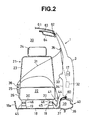
- FIG. 2 is an elevational view of the main portion of the present invention when the doors are closed.
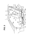
- FIG. 3 is a side view illustrating the seat belt movement when the doors are being opened.
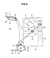
- FIG. 4 is an elevational view of the main portion of the present invention when the doors are open.
- FIG. 5 is an enlarged view showing the front attaching structure of the rail member.
- FIG. 6 is a top plan view showing the front attaching structure of the rail member.
- FIG. 7 is a rear view showing the front attaching structure of the rail member.
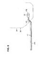
- FIG. 8 is a top plan view showing the rear attaching structure of the rail member.
- FIG. 9 is an exploded perspective view showing the main portion of the weight detecting means.
- FIG. 10 is an elevational view showing another preferred embodiment of the invention regarding a seat belt system for vehicles.
-
- Preferred embodiments of the present invention will now be described with reference to the drawings.
- The drawings show a seat belt system for a vehicle. Firstly, with reference to FIG. 1 to FIG. 4, a body structure and a door structure will be described.
- As shown in FIG. 1 and FIG. 3, side doors are disposed on the side portions of a body of a
vehicle 1. The side doors consist of afront door 2 and arear door 3 which are supported on the side portion of a body of thevehicle 1 via front-door hinges 4 and rear-door hinges 5 attached on the a leading edge of thefront door 2 and a trailing edge of therear door 3, respectively, constituting a side door structure in a free style configuration, or so-called a double door configuration. - The
front door 2 and therear door 3 comprisedoor panels 6, 7,door sashes door windows door panel 6 and door panel 7 (specifically, in the interspace defined by a door inner-panel and a door-outer panel), side impact bars (not shown) extend substantially in the vehicular longitudinal direction, respectively. - On the
front door 2, a side mirror for rearward visibility and an outside door-handle (not shown) for unlatch operation of thefront door 2 from the outside are preferably disposed. - In the double door configuration according to this embodiment, the
rear door 3 is prohibited from opening unless thefront door 2 is initially opened. - Inboardly adjacent to the side doors in the closed position illustrated in FIG. 1, a front ingress and egress opening 13a for a front passenger and a rear ingress and egress opening 13b for a rear passenger as door openings (side openings of the vehicle) are continuously formed to provide a substantially
continuous opening 13, whereby a B-post- or center-pillar-less body structure is obtained. Theopenings doors rear door 3, thelocks rear door 3 between the body side and a striker. At the middle portion of the leading edge of therear door 3, alock 17 is provided on thefront door 2 for locking astriker 16. - Additionally, as shown in FIG. 2 and FIG. 3, a
front seat 21 is mounted on or to afloor panel 18 preferably viabrackets system 20.
Thefront seat 21 comprises aseat cushion 22, a seat back 23, and aheadrest 24. Abuckle 25 is provided preferably on or mounted to theseat cushion 22 of thefront seat 21 so as to be adjacent to atunnel 18a. Thebuckle 25 is fixedly secured to the seat cushion bracket of theseat cushion 22 via astalk 26. - The rear portion of the
floor panel 18 is stepped upwardly to unitarily or integrally form a kick-up or step 27. On the top deck surface (the top surface) of the kick-up 27, aseat cushion 29 of arear seat 28 is mounted. Thus, as shown in FIG. 3, in apassenger compartment 30 of thevehicle 1, plural rows ofseats - FIG. 2 is a partial elevational view showing the
front seat 21 and therear door 3 in the closed state, and FIG. 4 is a partial elevational view showing therear door 3 in the open state. The drawings depict aseat belt webbing 31 for restraining the occupant in thefront seat 21. - This
seat belt webbing 31 is retracted by aretractor 32 disposed on a front structural door-member 3a of therear door 3. The front structural door-member 3a has the equivalent rigidity to that of a center-pillar which would be otherwise provided. - The lower half of the inboard side of the
rear door 3 is at least partly covered with adoor trim 34 having anarmrest 33. Additionally, at the upper portion of the inboard side of the front structural door-member 3a, ashoulder anchor 35 is attached so as to substantially face or to be substantially adjacent to the flank ofheadrest 24 of thefront seat 21 when therear door 3 is substantially closed. - The
seat belt webbing 31 is so arranged as to extend from theretractor 32 through the upper edge of the door trim 34 along the inboard side of the front structural door-member 3a, and reaches thepassenger compartment 30 through theshoulder anchor 35. Theshoulder anchor 35 supports a portion of the extended length of theseat belt webbing 31. - On an extended length of the
seat belt webbing 31, atongue 36 is slidably or displaceably provided. The distal end, or the lower end of theseat belt webbing 31 is connected to the lower edge of the door opening 13 so as to be slidable substantially back and forth or along the vehicular longitudinal direction, as shown in FIG. 3. - The sliding structure of the lower end of the
seat belt webbing 31 will be described in detail hereinafter. - As shown in FIG. 2 and FIG. 3, along both lateral sides of the floor panel 18 (only one of which is show in the drawings), a
side sill 40, which is a structural member and includes a substantially closedcross-section 39 defined by a side-sill inner 37 and a side-sill outer 38, is disposed. Arail member 41, which is preferably formed from a metallic cylindrical pipe, is fixedly secured viabolts sill 40. - FIG. 5, FIG. 6, and FIG. 7 show the overall construction and attaching structure of the frontal portion of the
rail member 41. FIG. 8 shows the overall construction and attaching structure of the rear portion of therail member 41. - As shown in FIG. 5, FIG. 6 and FIG. 7, the
rail member 41 includes a front attachedportion 41a in a substantially planar shape formed by pressing or deforming the metallic pipe, and aslide portion 41b which guides the anchor 44 (a slider) of theseat belt webbing 31 substantially in the vehicular longitudinal direction. - In addition, as shown in FIG. 5, the
rail member 41 includes acurved portion 41e between the front attachedportion 41a and theslide portion 41b. As shown, thecurved portion 41e forwardly and downwardly extends from the front attachedportion 41a to a front-lower end 41c, and curves rearwardly and upwardly from the front-lower end 41c to theslide portion 41b. The front attachedportion 41a is to be attached or mounted to thefront seat 21 as will be described later. Moreover, as shown in FIG. 6, thecurved portion 41e is formed so as to deviate outboardly (towards the side-sill 40) in the vehicular lateral direction from the front attachedportion 41a towards thefront end 41d of theslide portion 41b. - Here, the
anchor 44 of the seat belt webbing 31 (specifically of the lap belt as shown in FIG. 2) has a predetermined longitudinal length along the sliding direction (along the back and forth direction) and is slidably fitted onto or mounted to theslide portion 41 b of therail member 41. - The curved portion upwardly curving from the front-
lower end 41c of therail member 41 has such a small curvature and/or shape as to prevent theanchor 44 from sliding onto thecurved portion 41e from above.
Additionally, the predetermined longitudinal length of theanchor 44 may be preferably set so as to prevent itself from sliding onto the curved portion upwardly curving from the front-lower end 41 c. - The front attached
portion 41a of therail member 41 is to be fixedly secured to anextension 46a extending rearwardly from a load transfer means 46 as a part of aweight detecting means 45 viabolt 42 as described above. - On the other hand, as shown in FIG. 3 and FIG. 8, the rear portion of the
rail member 41 includes a bending portion 41f bending downwardly and inboardly in the vehicular lateral direction from theslide portion 41b, and a rear attachedportion 41g in a planar shape formed unitarily with the bending portion 41f. The rear attachedportion 41g is to be fixed on thetop deck surface 27a rearward of the kick-up 27 via thebolt 43 as described above. The fixed portion is concealed by theseat cushion 29 of therear seat 28 when viewed from above. In the meantime, theweight detecting means 45 is disposed between theseat sliding system 20 for thefront seat 21 and theseat bracket 19 on thefloor panel 18, as shown in FIG. 2 and FIG. 3. The weight detecting means is provided for detecting the weight acting on thefront seat 21. - As shown in FIG. 7, the
seat sliding system 20 described above comprises: alower rail 47; anupper rail 48; and a plurality of balls orglide members 49... disposed between theupper rail 48 and thelower rail 47. A pair ofseat sliding systems 20 is disposed below the driver's seat. Likewise, a pair ofseat sliding systems 20 is disposed below the front-passenger's seat. Corresponding to the fourseat sliding systems 20, four sets of theweight detecting means 45 are provided in total. - FIG. 9 is an exploded perspective view showing the main parts of the
weight detecting means 45. As shown, theweight detecting means 45 comprises: aload detecting portion 52 having a substantially U-shaped cross-section and including a pair ofarms 50 and a load sensor 51 (such as a strain member) for detecting the weight of the occupant and/or the weight acting on the respective seat; abase member 53 having a U-shape cross-section and supporting theload detecting portion 52; and theload transfer member 46 which transfers the load acting on thefront seat 21 to theload detecting portion 52. - The
base member 53 substantially extends in the vehicular longitudinal direction, with approximately the same longitudinal length as thelower rail 47 in theseat sliding system 20. Thebase member 53 is to be fixedly secured to thefloor panel 18 via theseat brackets - Two sets of the
load detecting portion 52 and theload transfer member 46 are provided at the front portion and rear portion of thebase member 53, respectively. In other words, a set of theload detecting portion 52 and theload transfer member 46 is provided at the front portion, and the other set is provided at the rear portion. - FIG. 9 is an exploded perspective view showing the rear portion of the
weight detecting means 45. Thearm 50 and theload transfer member 46 are to be fixed to the inner portion of thebase member 53 viabolts nuts - Moreover, the
load transfer member 46 is to be fixedly secured to thelower rail 47 of theseat slide system 20 viabolts weight detecting means 45 is located in the vicinity to the rear edge of thefront seat 21. - Then, the load acting on the
load transfer member 46 slightly deflects thearm 50 preferably within the range up to about 5 degrees, so thatload acting portions arm 50 transfer the load to theload sensor 51. Theload sensor 51 picks up the mechanical strain of theload acting portion 50a in the form of an electrical signal to detect the weight of the occupant. - The detailed structure of the
weight detecting means 45 preferably may be the same as that disclosed in U.S. Pat. No. 6,323,444, or Japanese Unexamined Patent Publication No. 2000-258233. - The
load transfer member 46 is unitarily or integrally formed with theextension 46a extending substantially rearwardly at the rear portion of theload transfer member 46. Theextension 46a preferably is in an approximately cylindrical shape and slanted down to the rearward such that its rear end is located lower than its front end. Theextension 46a is to be fitted or provided with the front attachedportion 41 a of therail member 41 described above viabolt 42 as shown in FIG. 5, FIG. 6, and FIG. 7. With this structure, the front end (refer to the front attachedportion 41a) is disposed substantially on theseat 21 above theweight detecting means 45. - In the drawings, the
reference numeral 60 indicates a scuff plate e.g. made of plastic resin; 61 indicates a roof panel; 62 indicates a roof rail; 63 indicates a roof side rail outer; 64 indicates the roof side rail inner; and 65 and 66 indicate a bolt and a nut for fixing theseat bracket 19 to thefloor panel 18, respectively. - It should be noted that the drawings show only the structure on the left side of the vehicle, and the structures on the right and left sides are substantially symmetrically constructed.
- Next, the action of the seat belt system for a vehicle constructed as above will now be described.
- As shown by broken lines in FIG. 1 and by phantom lines α in FIG. 3, when the
rear door 3 is in the closed state, theseat belt webbing 31, theshoulder anchor 35 and thetongue 36 are so arranged as to substantially face or correspond to the flank of the seat back 23 and head rest 24 of thefront seat 21. When the front passenger pulls theseat belt webbing 31 to fasten the seat belt, the lower end portion of the seat belt webbing attached to the anchor 44 (a movable anchor, or the slider) is caused to move to a forward position in the vicinity of thefront seat 21 along theslide portion 41b of therail member 41. - Therefore, as shown in FIG. 2, the engagement of the clasp at the tip of the
tongue 36 with thebuckle 25 results in the three-point seat belt restraint configuration for restraining the occupant in thefront seat 21. - When the occupant in the front seat is preferably restricted by the
seat belt webbing 31, the presence of the occupant can be accurately detected by theweight detecting means 45 without being affected by tension in theseat belt webbing 31, because the front end of therail member 41 is fixed substantially on theseat 21 above theweight detecting means 45. (In contrast to this, if the front end of therail member 41 is fixed under portion of theweight detecting means 45, thefloor panel 18 for example, tension in theseat belt webbing 31 acts as additional load on theload detecting means 45, and as a result the presence of the occupant cannot be accurately detected.) - On the other hand, when the
rear door 3 is opened after the front passenger unlatches theseat belt 31 and opens thefront door 2, the opening motion of therear door 3 pulls theseat belt webbing 31 rearwardly. Accordingly, as showing in FIG. 3, the lower portion of the seat belt webbing attached to theanchor 44 moves to a rearward position or direction along theslide portion 41b of therail member 41, causing no interference with the legs of the rear passenger during egress from thevehicle 1. This is also the case with respect to passenger ingress to thevehicle 1. Therefore, during both the ingress and egress of the rear passenger, theseat belt webbing 31 causes no interference with the passenger. - As described above, in accordance with the embodiment of the present invention shown in FIG. 1 to FIG. 9, there is provided a seat belt system for a vehicle, comprising the
retractor 32 disposed in therear door 3 for retracting theseat belt webbing 31 for restraining the occupant in the front seat, and theanchor 44 of theseat belt webbing 31 disposed laterally adjacent to thefront seat 21, wherein,
therail member 41 is provided for allowing theanchor 44 of theseat belt webbing 31 to slide substantially in the vehicular longitudinal direction,
theweight detecting means 45 is disposed between thefront seat 21 and thefloor panel 18 for detecting weight acting on thefront seat 21,
thebuckle 25 capable of engaging thetongue 36 of theseat belt webbing 31 is disposed on or mounted to theseat 21 above (or on a seat-side with respect to) theweight detecting means 45, and
the front end of therail member 41 is attached substantially on or to theseat 21 above (or on a seat-side with respect to) theweight detecting means 45. In other words, therail member 41 and/or thebuckle 25 are to be fixed with respect to theseat 21 without the interposition of theweight detecting means 45 thus not negatively influencing the weight detection by theweight detecting means 45 e.g. by the tension of theseat belt webbing 31. - According to this construction, when the
seat belt webbing 31 is retractably reeled out from theretractor 32 in therear door 3 and thetongue 36 of theseat belt webbing 31 engages thebuckle 25, the three-point seat belt restraint configuration for restraining the occupant in the front seat (refer to FIG. 2) is attained. - On the other hand, when the
rear door 3 is opened after theseat belt webbing 31 is released, the opening motion of therear door 3 causes theanchor 44 of the seat belt webbing 31 (or the lap belt) to rearwardly move along therail member 41. This prevents theseat belt webbing 31 from interfering with the ingress and egress of the rear passengers. - Furthermore, when the
seat belt webbing 31 is fastened, the presence of passenger can be detected without being influenced by the seat belt tension, because the front end of therail member 41 is attached substantially on theseat 21 above (or on a seat-side with respect to) theweight detecting means 45 or is attached between theweight detecting means 45 and a structure of theseat 21. This ensures accurate weight detection by theweight detecting means 45. In other words, therail member 41 is to be fixed with respect to theseat 21 without the interposition of theweight detecting means 45 thus not negatively influencing the weight detection by theweight detecting means 45 e.g. by the tension of theseat belt webbing 31. - The
weight detecting means 45 includes theload detecting portion 52 which detects load of the passenger, thebase member 53 which supports theload detecting portion 52, theload transfer member 46 which transfers the load acting on thefront seat 21 to theload detecting portion 52, wherein, the front attachedportion 41 a of therail member 41 is fixed on theload transfer member 46. - According to this construction, there is no need for additional parts for fixing the rail member because the
rail member 41 is fixed efficiently utilizing theload transfer member 46 of theweight detecting means 45, which reduces the number of parts. - Moreover, as described with reference to FIG. 5 and FIG. 6, the rear portion of the
weight detecting means 45 is located in the vicinity of the rear end portion of theseat cushion 22 of thefront seat 21; the front attachedportion 41a of therail member 41 is fixed to theextension 46a extending rearwardly from the rear end of theload transfer member 46; and therail member 41 includes thecurved portion 41e between the front attachedportion 41a and theslide portion 41b on which theanchor 44 slides, thecurved portion 41e firstly extending forwardly and downwardly from the front attachedportion 41a and then curving upwardly and rearwardly, and deviating outboardly in the vehicular lateral direction from the front attachedportion 41a towards thefront end 41d of theslide portion 41b. - According to this construction, the anchor point is surely provided avoiding the interference with other parts such as a reclining mechanism provided in the
front seat 21, because therail member 41 is constructed so as to have thecurved portion 41e which outboardly deviates towards the front end of theslide portion 41b.
Here, in this embodiment, the point "AP" shown in FIG. 5 actually serves as an anchor point. - Moreover, the
anchor 44 of theseat belt webbing 31 has a predetermined longitudinal length along the sliding direction and is slidably fitted onto theslide portion 41b of therail member 41. On the other hand, the curvature of thecurved portion 41e curving upwardly in the rail member 41 (refer to the curvature of the front-lower end 41c) is preferably set to so a small curvature as to prevent theanchor 44 from sliding onto thecurved portion 41e. Alternatively or additionally, the cross-section of therail member 41 at or near thecurved portion 41e may be set or shaped such that theslider 44 cannot move or slide thereonto. - According to this construction, the curvature of the
curved portion 41e set as above prevents theanchor 44 from sliding onto the curvature which upwardly curves, thereby avoiding the rearward movement of the anchor point after theseat belt webbing 31 is fastened. - Furthermore, the longitudinal length of the
anchor 44 is set to a predetermined length which prevents itself from sliding onto thecurved portion 41e upwardly curving (refer to the front-lower end 41c).
According to this construction, theanchor 44 is prevented from sliding onto thecurved portion 41e by the predetermined longitudinal length of theanchor 44 itself. - FIG. 10 shows another preferred embodiment of the invention regarding a seat belt system for a vehicle. Although the
buckle 25 is fixed to theseat cushion 22 via thestalk 26 in the embodiment shown in FIG. 2, thebuckle 25 may be fixed to thefloor panel 18 via abuckle bracket 67 in this embodiment shown in FIG. 10. - The detailed description of this embodiment is omitted, with showing FIG. 10 given the identical reference numerals for the identical elements to those shown in FIG. 2, because this embodiment is similar to the preceding embodiment in other construction, function, and advantage.
- With respect to the correspondence between the elements of the present invention and the embodiments described above, the front seat in the present invention corresponds to the
front seat 21 in the embodiment. Similarly, the floor corresponds to thefloor panel 18; the buckle means corresponds to thebuckle 25; and the tongue corresponds to thetongue member 36. However, the present invention is not limited to the construction in the embodiments described above. - For example, the portion on which the rear portion of the
rail member 41 is attached may be the corresponding portion thereto of the side-sill inner 37, in place of the top deck surface rearward of the kick-up 27. - According to the present invention, a seat belt system for vehicles is provided which does not interfere with the ingress and egress of the rear seat passenger, and can detect the presence of an occupant without being influenced by the seat belt tension to provide the accurate weight detection, by attaching the front end of the rail member which allows the seat belt anchor to slide in the vehicular longitudinal direction on the seat side above a weight detecting means.
-
- 3 ...
- rear door
- 18 ...
- floor panel
- 21 ...
- front seat
- 22 ...
- seat cushion
- 25 ...
- buckle
- 31 ...
- seat belt webbing
- 32 ...
- retractor
- 36 ...
- tongue
- 41 ...
- rail member
- 41a ...
- front attached portion
- 41b ...
- slide portion
- 41d ...
- front end of slide portion
- 41e ...
- curved portion
- 44 ...
- anchor
- 45 ...
- weight detecting means
- 46 ...
- load transfer member
- 46a ...
- extension
- 52 ...
- load detecting portion
- 53 ...
- base member
Claims (10)
- A seat belt system mountable to a vehicular body, comprising
a retractor (32) to be disposed at a rear door (3) for retracting a seat belt webbing (31) for restraining an occupant in a front seat (21),
an anchor (44) of the seat belt webbing (31) to be disposed laterally adjacent to the front seat (21),
a rail member (41) to be attached to the vehicle at a front attached portion (41a) and a rear attached portion (41g), for allowing said anchor (44) of the seat belt webbing (31) to slide substantially in the vehicular longitudinal direction, and
a weight detecting means (45) to be disposed between the front seat (21) and a floor panel (18) for detecting weight acting on the front seat (21),
wherein, said front attached portion (41a) is to be attached substantially on the seat (21) above said weight detecting means (45). - A seat belt system mountable to a vehicular body as defined in Claim 1, further comprising a buckle (25) to be disposed on the seat (21) above the weight detecting means (45), capable of engaging a tongue (36) of the seat belt webbing (21).
- A seat belt system mountable to a vehicular body as defined in any one of the preceding Claims, wherein, said weight detecting means (45) includes
a load detecting portion (52) which detects load of the passenger,
a base member (53) which supports said load detecting portion (52), and
a load transfer member (46) which transfer load acting on the front seat (21) to said load detecting portion (52),
wherein, said front attached portion (41a) of said rail member (41) is fixed to said load transfer member (46). - A seat belt system mountable to a vehicular body as defined in any one of the preceding claims,
wherein, the rear portion of said weight detecting means (45) is located in the vicinity of the rear end portion of a seat cushion of the front seat (21). - A seat belt system mountable to a vehicular body as defined in any one of the preceding claims,
wherein, said front attached portion (41a) of said rail member (41) is fixed to an extension extending rearwardly from the rear end of said load transfer member (46), and
said rail member (41) includes a curved portion (41e) between said front attached portion (41a) and a slide portion (41b) on which said anchor (44) slides, said curved portion (41e) firstly extending forwardly and downwardly from said front attached portion (41a) and then curving upwardly and rearwardly, and deviating outboardly in the vehicular lateral direction from said front attached portion (41 a) towards the front end of said slide portion (41 b). - A seat belt system mountable to a vehicular body as defined in claim 5,
wherein, said curved portion (41e) is formed so as to prevent said anchor (44) from sliding onto said curved portion (41e). - A seat belt system mountable to a vehicular body as defined in claim 6,
wherein, said anchor (44) of the seat belt webbing (31) has a predetermined longitudinal length along the sliding direction and is slidably fitted onto said slide portion (41 b) of said rail member (41), and
the curvature of said curved portion (41e) curving upwardly in said rail member (41) is set so a small curvature as to prevent said anchor (44) from sliding onto said curved portion (41e). - A seat belt system mountable to a vehicular body as defined in claim 6 or 7,
wherein, the longitudinal length of the anchor (44) is set to a predetermined length which prevents itself from sliding onto the curved portion (41e) upwardly curving. - A vehicle equipped with the seat belt system as defined in any one of the preceding claims.
- A vehicle as defined in Claim 9, the vehicle comprising,
a door opening (13),
a front door (2) swingably supported at the front edge of the door opening (13), and
the rear door (3) swingably supported at the rear edge of the door opening (13),
wherein the front door (2) and the rear door (3) can cooperatively close the door opening (13).
Applications Claiming Priority (2)
| Application Number | Priority Date | Filing Date | Title |
|---|---|---|---|
| JP2002040015 | 2002-02-18 | ||
| JP2002040015A JP3695403B2 (en) | 2002-02-18 | 2002-02-18 | Vehicle seat belt device |
Publications (2)
| Publication Number | Publication Date |
|---|---|
| EP1336539A1 true EP1336539A1 (en) | 2003-08-20 |
| EP1336539B1 EP1336539B1 (en) | 2004-11-10 |
Family
ID=27621474
Family Applications (1)
| Application Number | Title | Priority Date | Filing Date |
|---|---|---|---|
| EP03003581A Expired - Lifetime EP1336539B1 (en) | 2002-02-18 | 2003-02-17 | seat belt system for vehicles and vehicle provided therewith |
Country Status (4)
| Country | Link |
|---|---|
| US (1) | US6824167B2 (en) |
| EP (1) | EP1336539B1 (en) |
| JP (1) | JP3695403B2 (en) |
| DE (1) | DE60300134T2 (en) |
Cited By (3)
| Publication number | Priority date | Publication date | Assignee | Title |
|---|---|---|---|---|
| FR2855126A1 (en) * | 2003-05-19 | 2004-11-26 | Peugeot Citroen Automobiles Sa | Passenger retaining device for motor vehicle, has displacement unit to displace connection rail relative to chassis in case of collision of vehicle, such that stress is exerted by flexible strap on abdomen of passenger |
| EP1348602A3 (en) * | 2002-03-28 | 2005-04-27 | Mazda Motor Corporation | Front seatbelt system for vehicle |
| EP1580088A1 (en) * | 2004-03-22 | 2005-09-28 | Key Safety Systems, Inc. | Belt pretensioner |
Families Citing this family (8)
| Publication number | Priority date | Publication date | Assignee | Title |
|---|---|---|---|---|
| US7416218B2 (en) * | 2003-01-24 | 2008-08-26 | Takata Corporation | Seat belt device |
| US7537242B2 (en) * | 2003-01-24 | 2009-05-26 | Takata Corporation | Seat belt device |
| JP3800609B2 (en) | 2003-08-05 | 2006-07-26 | 本田技研工業株式会社 | Sheet device |
| JP2005239091A (en) * | 2004-02-27 | 2005-09-08 | Nissan Motor Co Ltd | Seat belt device |
| US8086073B2 (en) * | 2008-02-07 | 2011-12-27 | Seiko Epson Corporation | Non-uniform image resizer |
| US8408599B2 (en) * | 2009-09-16 | 2013-04-02 | GM Global Technology Operations LLC | Guide loops for a seat belt system |
| US8550499B2 (en) | 2010-12-09 | 2013-10-08 | Autoliv Asp, Inc. | Pyrotechnic lap belt pretensioner with slider bar function |
| CN108189800A (en) * | 2018-01-02 | 2018-06-22 | 苏州盱酋汽车科技有限公司 | A kind of door-opening type automobile front row slide rail type safety belt assembly conveniently got on or off the bus |
Citations (6)
| Publication number | Priority date | Publication date | Assignee | Title |
|---|---|---|---|---|
| US5149135A (en) * | 1988-06-15 | 1992-09-22 | Mazda Motor Corporation | Front seat shoulder belt and seat back supporting structure |
| EP0716963A1 (en) * | 1994-12-16 | 1996-06-19 | FIAT AUTO S.p.A. | Device for anchoring one end of a motor vehicle seat belt |
| EP1068970A1 (en) * | 1999-07-14 | 2001-01-17 | Mazda Motor Corporation | Side door structure for vehicle |
| JP2001138864A (en) * | 1999-11-11 | 2001-05-22 | Toyota Autom Loom Works Ltd | Automotive seat belt equipment |
| US6323444B1 (en) * | 1999-03-09 | 2001-11-27 | Takata Corporation | Seat weight measuring apparatus |
| EP1247703A1 (en) * | 2001-03-29 | 2002-10-09 | Mazda Motor Corporation | Seat belt system for vehicles and vehicle provided therewith |
Family Cites Families (6)
| Publication number | Priority date | Publication date | Assignee | Title |
|---|---|---|---|---|
| US4274657A (en) * | 1979-05-21 | 1981-06-23 | Rockwell International Corporation | Vehicle passive occupant restraining system |
| SE424812B (en) * | 1980-06-18 | 1982-08-16 | Stil Ind Ab | DEVICE AT THE VEHICLE SEAT BELT |
| JPS5869582A (en) * | 1981-10-22 | 1983-04-25 | 日産自動車株式会社 | Seat belt apparatus |
| US4817754A (en) * | 1987-04-27 | 1989-04-04 | Mazda Motor Corporation | Automotive seat belt system and retractor device for seat belt system |
| SE456983B (en) * | 1987-05-08 | 1988-11-21 | Autoliv Dev | FLOOR FIXED FOODS AND A SAFETY BALANCE OF THREE-POINT TYPE |
| JPH08142680A (en) | 1994-11-25 | 1996-06-04 | Nissan Shatai Co Ltd | Kannon door |
-
2002
- 2002-02-18 JP JP2002040015A patent/JP3695403B2/en not_active Expired - Lifetime
-
2003
- 2003-02-12 US US10/364,679 patent/US6824167B2/en not_active Expired - Lifetime
- 2003-02-17 DE DE60300134T patent/DE60300134T2/en not_active Expired - Lifetime
- 2003-02-17 EP EP03003581A patent/EP1336539B1/en not_active Expired - Lifetime
Patent Citations (6)
| Publication number | Priority date | Publication date | Assignee | Title |
|---|---|---|---|---|
| US5149135A (en) * | 1988-06-15 | 1992-09-22 | Mazda Motor Corporation | Front seat shoulder belt and seat back supporting structure |
| EP0716963A1 (en) * | 1994-12-16 | 1996-06-19 | FIAT AUTO S.p.A. | Device for anchoring one end of a motor vehicle seat belt |
| US6323444B1 (en) * | 1999-03-09 | 2001-11-27 | Takata Corporation | Seat weight measuring apparatus |
| EP1068970A1 (en) * | 1999-07-14 | 2001-01-17 | Mazda Motor Corporation | Side door structure for vehicle |
| JP2001138864A (en) * | 1999-11-11 | 2001-05-22 | Toyota Autom Loom Works Ltd | Automotive seat belt equipment |
| EP1247703A1 (en) * | 2001-03-29 | 2002-10-09 | Mazda Motor Corporation | Seat belt system for vehicles and vehicle provided therewith |
Non-Patent Citations (1)
| Title |
|---|
| PATENT ABSTRACTS OF JAPAN vol. 2000, no. 22 9 March 2001 (2001-03-09) * |
Cited By (4)
| Publication number | Priority date | Publication date | Assignee | Title |
|---|---|---|---|---|
| EP1348602A3 (en) * | 2002-03-28 | 2005-04-27 | Mazda Motor Corporation | Front seatbelt system for vehicle |
| US6959947B2 (en) | 2002-03-28 | 2005-11-01 | Mazda Motor Corporation | Front seatbelt system for vehicle |
| FR2855126A1 (en) * | 2003-05-19 | 2004-11-26 | Peugeot Citroen Automobiles Sa | Passenger retaining device for motor vehicle, has displacement unit to displace connection rail relative to chassis in case of collision of vehicle, such that stress is exerted by flexible strap on abdomen of passenger |
| EP1580088A1 (en) * | 2004-03-22 | 2005-09-28 | Key Safety Systems, Inc. | Belt pretensioner |
Also Published As
| Publication number | Publication date |
|---|---|
| US6824167B2 (en) | 2004-11-30 |
| US20030178835A1 (en) | 2003-09-25 |
| EP1336539B1 (en) | 2004-11-10 |
| JP3695403B2 (en) | 2005-09-14 |
| DE60300134T2 (en) | 2005-11-03 |
| DE60300134D1 (en) | 2004-12-16 |
| JP2003237531A (en) | 2003-08-27 |
Similar Documents
| Publication | Publication Date | Title |
|---|---|---|
| US8336914B2 (en) | Seatbelt device of vehicle | |
| EP1336539B1 (en) | seat belt system for vehicles and vehicle provided therewith | |
| AU753427B2 (en) | A retractable automotive seat assembly | |
| WO2010083607A1 (en) | Lower tip-slide mechanism | |
| EP1247703B1 (en) | Seat belt system for vehicles and vehicle provided therewith | |
| US7364200B2 (en) | Vehicle seatbelt restraining apparatus | |
| EP1285824B1 (en) | Seat belt system for a vehicle | |
| JP5487753B2 (en) | Rear body structure of the vehicle | |
| JP3680580B2 (en) | Vehicle seat belt device | |
| EP0890489B1 (en) | A safety belt attachment system for the rear of a motor vehicle | |
| US4235456A (en) | Passive occupant restraint system | |
| JP4296953B2 (en) | Vehicle seat belt device | |
| EP0411809A1 (en) | Vehicle seat belt mounting | |
| JP2003237369A (en) | Vehicle door structure | |
| JP4039211B2 (en) | Automotive interior material arrangement structure | |
| JPH0724293Y2 (en) | Car seat belt equipment | |
| JP4582434B2 (en) | Vehicle seat belt structure | |
| JP3915492B2 (en) | Vehicle seat belt device | |
| JP3952839B2 (en) | Vehicle seat belt device and method of assembling the same | |
| JP3965990B2 (en) | Vehicle seat belt device | |
| JP5077417B2 (en) | Vehicle seat belt structure | |
| JP2589763B2 (en) | Automotive seat belt equipment | |
| CN120307966A (en) | Vehicle structure | |
| JP2003252171A (en) | Seat belt anchor mounting structure | |
| JP2011084233A (en) | Upper body structure of vehicle |
Legal Events
| Date | Code | Title | Description |
|---|---|---|---|
| PUAI | Public reference made under article 153(3) epc to a published international application that has entered the european phase |
Free format text: ORIGINAL CODE: 0009012 |
|
| AK | Designated contracting states |
Designated state(s): AT BE BG CH CY CZ DE DK EE ES FI FR GB GR HU IE IT LI LU MC NL PT SE SI SK TR |
|
| AX | Request for extension of the european patent |
Extension state: AL LT LV MK RO |
|
| GRAP | Despatch of communication of intention to grant a patent |
Free format text: ORIGINAL CODE: EPIDOSNIGR1 |
|
| 17P | Request for examination filed |
Effective date: 20040108 |
|
| AKX | Designation fees paid |
Designated state(s): DE |
|
| GRAS | Grant fee paid |
Free format text: ORIGINAL CODE: EPIDOSNIGR3 |
|
| GRAA | (expected) grant |
Free format text: ORIGINAL CODE: 0009210 |
|
| AK | Designated contracting states |
Kind code of ref document: B1 Designated state(s): DE |
|
| REG | Reference to a national code |
Ref country code: IE Ref legal event code: FG4D |
|
| REF | Corresponds to: |
Ref document number: 60300134 Country of ref document: DE Date of ref document: 20041216 Kind code of ref document: P |
|
| PLBE | No opposition filed within time limit |
Free format text: ORIGINAL CODE: 0009261 |
|
| STAA | Information on the status of an ep patent application or granted ep patent |
Free format text: STATUS: NO OPPOSITION FILED WITHIN TIME LIMIT |
|
| 26N | No opposition filed |
Effective date: 20050811 |
|
| PGFP | Annual fee paid to national office [announced via postgrant information from national office to epo] |
Ref country code: DE Payment date: 20110208 Year of fee payment: 9 |
|
| REG | Reference to a national code |
Ref country code: DE Ref legal event code: R119 Ref document number: 60300134 Country of ref document: DE Effective date: 20120901 |
|
| PG25 | Lapsed in a contracting state [announced via postgrant information from national office to epo] |
Ref country code: DE Free format text: LAPSE BECAUSE OF NON-PAYMENT OF DUE FEES Effective date: 20120901 |