EP1580088A1 - Belt pretensioner - Google Patents
Belt pretensioner Download PDFInfo
- Publication number
- EP1580088A1 EP1580088A1 EP04251646A EP04251646A EP1580088A1 EP 1580088 A1 EP1580088 A1 EP 1580088A1 EP 04251646 A EP04251646 A EP 04251646A EP 04251646 A EP04251646 A EP 04251646A EP 1580088 A1 EP1580088 A1 EP 1580088A1
- Authority
- EP
- European Patent Office
- Prior art keywords
- pretensioner according
- seat belt
- pretensioner
- vehicle
- rail
- Prior art date
- Legal status (The legal status is an assumption and is not a legal conclusion. Google has not performed a legal analysis and makes no representation as to the accuracy of the status listed.)
- Granted
Links
Images


Classifications
-
- B—PERFORMING OPERATIONS; TRANSPORTING
- B60—VEHICLES IN GENERAL
- B60R—VEHICLES, VEHICLE FITTINGS, OR VEHICLE PARTS, NOT OTHERWISE PROVIDED FOR
- B60R22/00—Safety belts or body harnesses in vehicles
- B60R22/02—Semi-passive restraint systems, e.g. systems applied or removed automatically but not both ; Manual restraint systems
- B60R22/022—Semi-passive restraint systems, e.g. systems applied or removed automatically but not both ; Manual restraint systems with means for facilitating access to rear seats in two-door cars
-
- B—PERFORMING OPERATIONS; TRANSPORTING
- B60—VEHICLES IN GENERAL
- B60R—VEHICLES, VEHICLE FITTINGS, OR VEHICLE PARTS, NOT OTHERWISE PROVIDED FOR
- B60R22/00—Safety belts or body harnesses in vehicles
- B60R22/18—Anchoring devices
- B60R22/195—Anchoring devices with means to tension the belt in an emergency, e.g. means of the through-anchor or splitted reel type
- B60R22/1951—Anchoring devices with means to tension the belt in an emergency, e.g. means of the through-anchor or splitted reel type characterised by arrangements in vehicle or relative to seat belt
-
- B—PERFORMING OPERATIONS; TRANSPORTING
- B60—VEHICLES IN GENERAL
- B60R—VEHICLES, VEHICLE FITTINGS, OR VEHICLE PARTS, NOT OTHERWISE PROVIDED FOR
- B60R22/00—Safety belts or body harnesses in vehicles
- B60R22/18—Anchoring devices
- B60R22/22—Anchoring devices secured to the vehicle floor
-
- B—PERFORMING OPERATIONS; TRANSPORTING
- B60—VEHICLES IN GENERAL
- B60R—VEHICLES, VEHICLE FITTINGS, OR VEHICLE PARTS, NOT OTHERWISE PROVIDED FOR
- B60R22/00—Safety belts or body harnesses in vehicles
- B60R22/18—Anchoring devices
- B60R22/195—Anchoring devices with means to tension the belt in an emergency, e.g. means of the through-anchor or splitted reel type
- B60R22/1952—Transmission of tensioning power by cable; Return motion locking means therefor
Definitions
- the present invention relates to a pretensioner and particularly to a pretensioner for a vehicle safety restraint mechanism such as a seat belt.
- a seat belt safety restraint comprises a length of belt webbing connected at three points to load bearing parts of a vehicle.
- one end is bolted to a door sill on one side of the seat, arranged to pass laterally across the hips of the seat occupant to a buckle mechanism fixed to the vehicle on the opposite side of the seat, and then diagonally across the torso of the occupant to a further fastening point on the B pillar of the door.
- the buckle mechanism engages a buckle tongue slidably attached to the webbing.
- a retractor is fitted at the pillar end of the webbing. This allows the webbing to pay out under relatively low loads to enable limited movement of the restrained occupant, for example to reach in-car entertainment controls or storage compartments.
- the retractor is biased to keep the webbing relatively taut about the occupant and a locking element is included to lock the retractor against webbing pay out in the event of a dangerous situation being detected.
- an acceleration sensor activates if the vehicle undergoes rapid acceleration or deceleration indicative of a crash.
- pretensioners have been introduced to rapidly pull in a length of webbing to actively tighten the belt about the vehicle occupant in the event of a crash condition being sensed. This takes up any slack which may have developed in the belt and helps to more correctly position the occupant in the seat to maximise the effect of the belt protection and of any secondary safety restraint such as an air bag.
- Pretensioners comprise a force reservoir such as a pyrotechnically operated gas generator to provide an impulse of sufficient magnitude to tighten the belt in a short space of time, ideally before the crash pulse takes full effect.
- a typical known pretensioner uses rotational means to wind in a length of seat belt webbing, for example by rotating the retractor spool in a webbing rewind direction to take in the required length of webbing prior to the retractor locking against webbing pay out.
- known pretensioners tend to be bulky, and are particularly difficult to use for the driver, and front passenger, seat of a three door vehicle because of the requirement to allow access to the rear of the vehicle past the front seats.
- Using a traditional retractor pretensioner mechanism in a front seat of a three door vehicle causes an unacceptable obstruction.
- the present invention provides an improved pretensioning mechanism which can be used in three-door, front seat applications.
- a pretensioner for a three point vehicle safety restraint seat belt comprising a mounting for one end of the seat belt, the mounting comprising a first member fixed to a load bearing part of the vehicle and a second member attached to the end of the seat belt, and means for moving the second member translationally relative to the first member in a pretensioning direction in response to activation of a crash sensor.
- the means for moving the second member comprises a force reservoir such as a pyrotechnically operated gas cylinder.
- a force reservoir such as a pyrotechnically operated gas cylinder.
- a pyrotechnic unit is particularly suited to this application since it provides an impulse of the required magnitude over a short time period.
- the first member is a rail and the second member may advantageously be arranged to slide in only the pretensioning direction along the rail upon activation of the force reservoir, being restrained from return motion in the opposite direction, for example by a ratchet mechanism comprising teeth incorporated into a surface of the rail.
- Ratchets are known for different seat belt restraint applications and so the pretensioner of the present invention can advantageously be constructed using standard parts and manufacturing processes, and thus offers a relatively low cost locking mechanism.
- a piston and a cylinder housing arrangement may be connected by a cable to the second member such that activation of the force reservoir drives the piston along the cylinder and the piston pulls the cable and thus pulls the second member along the rail.
- Pretensioners can be constructed according to the invention which have reduced or eliminated obstruction to rear seat access, smaller package sizes and which are attached to an appropriate sill anchorage zone.
- Positioning the piston and cylinder below the rail advantageously reduces the overall size of the pretensioner.
- the load bearing part of the vehicle is a longitudinal chassis member such as the front door sill.
- the second member may be connected to the seat belt webbing via a slider bar to provide suitable compact anchorage with flexibility to allow access to rear seats in a three-door vehicle.
- the crash sensor is activated when the vehicle exceeds a predetermined acceleration or deceleration threshold.
- Figure 1 shows a slider bar 10 positioned adjacent to a front seat 12 of a vehicle.
- One end of seat belt webbing 14 passes around the slider bar 10 and is free to move back and forth along the slider bar 10.
- the seat belt webbing 14 is of a conventional design and is attached at one end to a retractor mounted, adjacent a seat, to a load bearing part of the vehicle such as a vehicle side pillar (not shown).
- the webbing passes through a shoulder support also attached to the side pillar and has a buckle tongue, which is insertable into a buckle (not shown) located on the other side of the seat.
- the seat belt webbing 14 When in use, the seat belt webbing 14 is at one end of the slider bar 10 in the load bearing position shown in Fig. 1. When the seat belt is not in use the end of the webbing 14 may be moved in a rearward direction along the slider bar 10 so that it does not obstruct access to the rear seat of the vehicle.
- the slider bar 10 is attached to a carriage 16 which is mounted on a rail 18.
- a cable 20 extends between the carriage 16 and a pyrotechnic unit 22.
- the pyrotechnic unit 22 is of a known type and contains a piston within a cylindrical housing and a gas generator.
- the gas generator is pyrotechnically activated to provide an impulse which forces the piston in a rearward direction and tensions the cable 20.
- FIG. 2 shows one arrangement of the carriage 16 and the rail 18 in greater detail.
- the rail 18 is attached at each end to support members 26 which are fixed to a load bearing chassis member 24 by means of bolts 28.
- a load bearing chassis member 24 may be a chassis member extending in a longitudinal direction down each side of the vehicle, or a load bearing door sill and provides a suitable load bearing anchorage zone for the slider bar 10 adjacent to and slightly to the rear of each of the vehicle doors.
- the carriage 16 Prior to pretensioning, the carriage 16 is positioned for normal use of the seat belt webbing 14 at its forward most position, at the right hand side as shown in figure 2 of the rail 18.
- a crash sensor Upon sensing an acceleration of the vehicle above a predetermined criteria, a crash sensor, in known manner, generates a signal indicative of a crash condition which causes the pyrotechnic unit 22 to fire, creating a tension in the metal cable 20.
- the tension in the cable 20 pulls the carriage 16 and the slider bar 10 in a rearward direction i.e. the direction of arrow A in figure 2.
- the carriage 16 can be arranged to move rearwardly a distance in the region of 50 to 150 mm depending on the vehicle size and requirements.
- the sudden movement of the slider bar 10 in a rearward direction provides tension in the seat belt webbing 14, which takes up any slack in the webbing 14 and pulls an occupant backwards into the seat 12 so as to correctly position the occupant within the seat 12 in order to maximise the benefit of the seat belt and correctly position him for maximum effect of any secondary restraint such as an air bag.
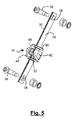
- Figure 3 shows the position of the carriage immediately after pretensioning. After the pyrotechnic unit has fired, the carriage 16 is prevented from returning to its original position under the forward momentum of the occupant during a crash, by a ratchet mechanism within the carriage 16 which is shown more clearly in figure 5.
- the rail 18 is attached at each of its ends to respective support members 26 by means of bolts 36 passing through cylindrical holes 38 at each end of the rail 18.
- Locking ratchet teeth 30 are formed in one surface of the rail 18.
- the carriage 16 has two end plates 40 and a base plate 42 attached to a side wall 44.
- a locking lever 32 extends from the base plate 42.
- Each of the end plates 40 and the locking lever 32 have a slot, allowing the rail 18 to pass through the centre of the carriage 16.
- An inner surface of the locking lever 32 is in contact with the teeth 30 in the surface of the rail 18 and is orientated at an angle such that the locking lever 32 can pass over the teeth 30 in one direction.
- the locking lever 32 is biased such that if it tries to move in the opposite direction, a locking edge of the inner surface of the locking lever 32 will be caught against a tooth 30 on the upper surface of the rail 18 and thus prevents the carriage 16 from sliding in a reverse direction.
- the teeth 30 may be of a saw-tooth form.
- the slider bar 10, the carriage 16 and ratchet mechanism, the rail 18, the support members 26 and the bolts 28, 36 and 46 are all preferably made of metal.
- the ratchet mechanism and the carriage 16 may be formed from both parts of a height adjuster traditionally used to alter the height of the belt shoulder support.
- the pyrotechnic unit is shown stored beneath the rail 18 and the bolts 36 and corresponding holes 38 in the rail may be used to fix the pyrotechnic unit 22 in relation to the rail 18.
- the operation of the pretensioner in figure 4 is substantially the same as that shown in figure 1, except that the cable 20 bends 180° in order to cater for the different orientation of the pyrotechnic unit 22.
Abstract
Description
- The present invention relates to a pretensioner and particularly to a pretensioner for a vehicle safety restraint mechanism such as a seat belt.
- Traditionally a seat belt safety restraint comprises a length of belt webbing connected at three points to load bearing parts of a vehicle. Typically one end is bolted to a door sill on one side of the seat, arranged to pass laterally across the hips of the seat occupant to a buckle mechanism fixed to the vehicle on the opposite side of the seat, and then diagonally across the torso of the occupant to a further fastening point on the B pillar of the door. The buckle mechanism engages a buckle tongue slidably attached to the webbing.
- To increase comfort for the occupant restrained by the belt, a retractor is fitted at the pillar end of the webbing. This allows the webbing to pay out under relatively low loads to enable limited movement of the restrained occupant, for example to reach in-car entertainment controls or storage compartments. The retractor is biased to keep the webbing relatively taut about the occupant and a locking element is included to lock the retractor against webbing pay out in the event of a dangerous situation being detected. For example, an acceleration sensor activates if the vehicle undergoes rapid acceleration or deceleration indicative of a crash.
- In recent years, pretensioners have been introduced to rapidly pull in a length of webbing to actively tighten the belt about the vehicle occupant in the event of a crash condition being sensed. This takes up any slack which may have developed in the belt and helps to more correctly position the occupant in the seat to maximise the effect of the belt protection and of any secondary safety restraint such as an air bag.
- Pretensioners comprise a force reservoir such as a pyrotechnically operated gas generator to provide an impulse of sufficient magnitude to tighten the belt in a short space of time, ideally before the crash pulse takes full effect. A typical known pretensioner uses rotational means to wind in a length of seat belt webbing, for example by rotating the retractor spool in a webbing rewind direction to take in the required length of webbing prior to the retractor locking against webbing pay out.
- However, known pretensioners tend to be bulky, and are particularly difficult to use for the driver, and front passenger, seat of a three door vehicle because of the requirement to allow access to the rear of the vehicle past the front seats. Using a traditional retractor pretensioner mechanism in a front seat of a three door vehicle causes an unacceptable obstruction.
- Seat travel is greater in a three door vehicle than in a four door vehicle in order to provide such access and to accommodate this the door sill end of the webbing is usually attached to a so-called slider bar of well known design, instead of being fixedly bolted to the floor. This allows the sill end of the webbing to be moved longitudinally forward and rearward to facilitate rear seat access and front seat movement.
- The present invention provides an improved pretensioning mechanism which can be used in three-door, front seat applications.
- According to the present invention there is provided a pretensioner for a three point vehicle safety restraint seat belt, comprising a mounting for one end of the seat belt, the mounting comprising a first member fixed to a load bearing part of the vehicle and a second member attached to the end of the seat belt, and means for moving the second member translationally relative to the first member in a pretensioning direction in response to activation of a crash sensor.
- According to one embodiment the means for moving the second member comprises a force reservoir such as a pyrotechnically operated gas cylinder. Such a pyrotechnic unit is particularly suited to this application since it provides an impulse of the required magnitude over a short time period.
- In a preferred embodiment of the invention the first member is a rail and the second member may advantageously be arranged to slide in only the pretensioning direction along the rail upon activation of the force reservoir, being restrained from return motion in the opposite direction, for example by a ratchet mechanism comprising teeth incorporated into a surface of the rail.
- Locking the pretensioner against return movement in this way prevents a loss of tension in the seat belt after pretensioning has been carried out. Ratchets are known for different seat belt restraint applications and so the pretensioner of the present invention can advantageously be constructed using standard parts and manufacturing processes, and thus offers a relatively low cost locking mechanism.
- A piston and a cylinder housing arrangement, advantageously located below the rail, may be connected by a cable to the second member such that activation of the force reservoir drives the piston along the cylinder and the piston pulls the cable and thus pulls the second member along the rail.
- The use of a rail is particularly beneficial since the pretensioning action can be constrained to a linear motion in one direction in a simple manner and without the need for complicated or bulky rotating parts. Pretensioners can be constructed according to the invention which have reduced or eliminated obstruction to rear seat access, smaller package sizes and which are attached to an appropriate sill anchorage zone.
- Positioning the piston and cylinder below the rail advantageously reduces the overall size of the pretensioner.
- According to a preferred embodiment, the load bearing part of the vehicle is a longitudinal chassis member such as the front door sill. The second member may be connected to the seat belt webbing via a slider bar to provide suitable compact anchorage with flexibility to allow access to rear seats in a three-door vehicle.
- Advantageously the crash sensor is activated when the vehicle exceeds a predetermined acceleration or deceleration threshold.
- For a better understanding of the present invention, and to show how the same may be carried into effect, reference will now be made, by way of example, to the accompanying drawings, in which:
- Figure 1 is a schematic side view of a pretensioner according to the present invention.
- Figure 2 is an enlarged view of part of the pretensioner of figure 1 before pretensioning.
- Figure 3 is an enlarged view of part of the pretensioner of figure 1 after pretensioning.
- Figure 4 is a side view of an alternative arrangement of the pretensioner of figure 1.
- Figure 5 is an enlarged perspective view of the carriage and rail arrangement of figure 1.
-
- Figure 1 shows a
slider bar 10 positioned adjacent to afront seat 12 of a vehicle. One end ofseat belt webbing 14 passes around theslider bar 10 and is free to move back and forth along theslider bar 10. - The
seat belt webbing 14 is of a conventional design and is attached at one end to a retractor mounted, adjacent a seat, to a load bearing part of the vehicle such as a vehicle side pillar (not shown). The webbing passes through a shoulder support also attached to the side pillar and has a buckle tongue, which is insertable into a buckle (not shown) located on the other side of the seat. - When in use, the
seat belt webbing 14 is at one end of theslider bar 10 in the load bearing position shown in Fig. 1. When the seat belt is not in use the end of thewebbing 14 may be moved in a rearward direction along theslider bar 10 so that it does not obstruct access to the rear seat of the vehicle. - One end of the
slider bar 10 is attached to acarriage 16 which is mounted on arail 18. Acable 20 extends between thecarriage 16 and apyrotechnic unit 22. Thepyrotechnic unit 22 is of a known type and contains a piston within a cylindrical housing and a gas generator. The gas generator is pyrotechnically activated to provide an impulse which forces the piston in a rearward direction and tensions thecable 20. - Figure 2 shows one arrangement of the
carriage 16 and therail 18 in greater detail. Therail 18 is attached at each end to supportmembers 26 which are fixed to a load bearingchassis member 24 by means ofbolts 28. Such a load bearingchassis member 24 may be a chassis member extending in a longitudinal direction down each side of the vehicle, or a load bearing door sill and provides a suitable load bearing anchorage zone for theslider bar 10 adjacent to and slightly to the rear of each of the vehicle doors. - Prior to pretensioning, the
carriage 16 is positioned for normal use of theseat belt webbing 14 at its forward most position, at the right hand side as shown in figure 2 of therail 18. Upon sensing an acceleration of the vehicle above a predetermined criteria, a crash sensor, in known manner, generates a signal indicative of a crash condition which causes thepyrotechnic unit 22 to fire, creating a tension in themetal cable 20. The tension in thecable 20 pulls thecarriage 16 and theslider bar 10 in a rearward direction i.e. the direction of arrow A in figure 2. Thecarriage 16 can be arranged to move rearwardly a distance in the region of 50 to 150 mm depending on the vehicle size and requirements. - The sudden movement of the
slider bar 10 in a rearward direction provides tension in theseat belt webbing 14, which takes up any slack in thewebbing 14 and pulls an occupant backwards into theseat 12 so as to correctly position the occupant within theseat 12 in order to maximise the benefit of the seat belt and correctly position him for maximum effect of any secondary restraint such as an air bag. - Figure 3 shows the position of the carriage immediately after pretensioning. After the pyrotechnic unit has fired, the
carriage 16 is prevented from returning to its original position under the forward momentum of the occupant during a crash, by a ratchet mechanism within thecarriage 16 which is shown more clearly in figure 5. - The
rail 18 is attached at each of its ends to respective supportmembers 26 by means ofbolts 36 passing throughcylindrical holes 38 at each end of therail 18. Lockingratchet teeth 30 are formed in one surface of therail 18. Thecarriage 16 has twoend plates 40 and abase plate 42 attached to aside wall 44. Alocking lever 32 extends from thebase plate 42. Each of theend plates 40 and thelocking lever 32 have a slot, allowing therail 18 to pass through the centre of thecarriage 16. - An inner surface of the
locking lever 32 is in contact with theteeth 30 in the surface of therail 18 and is orientated at an angle such that thelocking lever 32 can pass over theteeth 30 in one direction. However thelocking lever 32 is biased such that if it tries to move in the opposite direction, a locking edge of the inner surface of thelocking lever 32 will be caught against atooth 30 on the upper surface of therail 18 and thus prevents thecarriage 16 from sliding in a reverse direction. To facilitate this theteeth 30 may be of a saw-tooth form. - The
slider bar 10, thecarriage 16 and ratchet mechanism, therail 18, thesupport members 26 and thebolts carriage 16 may be formed from both parts of a height adjuster traditionally used to alter the height of the belt shoulder support. - In figure 4 the pyrotechnic unit is shown stored beneath the
rail 18 and thebolts 36 and correspondingholes 38 in the rail may be used to fix thepyrotechnic unit 22 in relation to therail 18. The operation of the pretensioner in figure 4 is substantially the same as that shown in figure 1, except that thecable 20 bends 180° in order to cater for the different orientation of thepyrotechnic unit 22.
Claims (13)
- A pretensioner for a three point vehicle safety restraint seat belt, comprising:a mounting for one end of the seat belt (14), the mounting comprising a first member (18) adapted to be fixed to a load bearing part (24) of the vehicle and a second member (16) attached to the end of the seat belt (14), andmeans for moving the second member (16) translationally relative to the first member (18) in a pretensioning direction in response to activation of a crash sensor.
- A pretensioner according to claim 1 wherein the mounting further comprises a slider bar connecting the second member to the end of the seat belt.
- A pretensioner according to claim 1 or claim 2 wherein said one end of the seat belt is the sill end.
- A pretensioner according to claim 3 wherein the load bearing part comprises a sill anchorage.
- A pretensioner according to any one of the preceding claims wherein the means for moving the second member (16) comprises a force reservoir.
- A pretensioner according to claim 5 wherein the means for moving further comprises a piston connected to the second member (16) and a cylinder housing the piston such that activation of the force reservoir drives the piston along the cylinder.
- A pretensioner according to claim 6 wherein the piston and cylinder are located below the first member (18).
- A pretensioner according to claims 5, 6 or 7 wherein the force reservoir comprises a gas generator which is pyrotechnically activated.
- A pretensioner according to any one of the preceding claims wherein the first member comprises a rail (18).
- A pretensioner according to any one of the preceding claims wherein the first member (18) comprises means for restraining motion of the second member (16) in a non-pretensioning direction.
- A pretensioner according to claim 10 wherein the restraining means comprises ratchet teeth (30) in one surface of the rail (18).
- A pretensioner according to any one of the preceding claims wherein the load bearing part (24) of the vehicle is a longitudinal chassis member.
- A pretensioner according to any one of the preceding claims wherein the crash sensor is activated upon the vehicle exceeding a predetermined acceleration or deceleration threshold.
Priority Applications (17)
| Application Number | Priority Date | Filing Date | Title |
|---|---|---|---|
| AT04251646T ATE352461T1 (en) | 2004-03-22 | 2004-03-22 | BELT TENSIONER |
| EP04251646A EP1580088B1 (en) | 2004-03-22 | 2004-03-22 | Belt pretensioner |
| ES04251646T ES2280906T3 (en) | 2004-03-22 | 2004-03-22 | BELT PRETENSOR. |
| DE602004004502T DE602004004502T2 (en) | 2004-03-22 | 2004-03-22 | pretensioners |
| DE602004009282T DE602004009282T2 (en) | 2004-03-22 | 2004-06-11 | pretensioners |
| AT04253510T ATE374710T1 (en) | 2004-03-22 | 2004-06-11 | BELT TENSIONER |
| EP04253510A EP1580089B1 (en) | 2004-03-22 | 2004-06-11 | Belt pretensioner |
| US10/874,911 US7219929B2 (en) | 2004-03-22 | 2004-06-24 | Seat belt pretensioner |
| AT04254459T ATE380133T1 (en) | 2004-03-22 | 2004-07-26 | BELT TENSIONER |
| DE602004010484T DE602004010484T2 (en) | 2004-03-22 | 2004-07-26 | pretensioners |
| ES04254459T ES2297341T3 (en) | 2004-03-22 | 2004-07-26 | BELT PRETENSOR. |
| EP04254459A EP1580090B1 (en) | 2004-03-22 | 2004-07-26 | Belt pretensioner |
| ES05251728T ES2357315T3 (en) | 2004-03-22 | 2005-03-22 | BELT PRETENSER. |
| AT05251728T ATE485196T1 (en) | 2004-03-22 | 2005-03-22 | BELT TENSIONER |
| EP07101690A EP1783011A3 (en) | 2004-03-22 | 2005-03-22 | Pretensioner |
| EP20050251728 EP1580091B1 (en) | 2004-03-22 | 2005-03-22 | Belt pretensioner |
| DE602005024205T DE602005024205D1 (en) | 2004-03-22 | 2005-03-22 | pretensioners |
Applications Claiming Priority (1)
| Application Number | Priority Date | Filing Date | Title |
|---|---|---|---|
| EP04251646A EP1580088B1 (en) | 2004-03-22 | 2004-03-22 | Belt pretensioner |
Publications (2)
| Publication Number | Publication Date |
|---|---|
| EP1580088A1 true EP1580088A1 (en) | 2005-09-28 |
| EP1580088B1 EP1580088B1 (en) | 2007-01-24 |
Family
ID=34854714
Family Applications (1)
| Application Number | Title | Priority Date | Filing Date |
|---|---|---|---|
| EP04251646A Expired - Lifetime EP1580088B1 (en) | 2004-03-22 | 2004-03-22 | Belt pretensioner |
Country Status (5)
| Country | Link |
|---|---|
| US (1) | US7219929B2 (en) |
| EP (1) | EP1580088B1 (en) |
| AT (2) | ATE352461T1 (en) |
| DE (2) | DE602004004502T2 (en) |
| ES (2) | ES2280906T3 (en) |
Families Citing this family (21)
| Publication number | Priority date | Publication date | Assignee | Title |
|---|---|---|---|---|
| US7263750B2 (en) | 2005-06-09 | 2007-09-04 | Amsafe, Inc. | Buckle assembly having single release for multiple belt connectors |
| ATE388055T1 (en) * | 2005-07-12 | 2008-03-15 | Key Safety Systems Inc | BELT TENSIONER |
| US20070235999A1 (en) * | 2006-04-06 | 2007-10-11 | Morra Mark A | Vehicle seat belt apparatus |
| US8303043B2 (en) | 2008-09-29 | 2012-11-06 | Amsafe, Inc. (Phoenix Group) | Tensioning apparatuses for occupant restraint systems and associated systems and methods |
| DE102009009390B4 (en) | 2009-02-18 | 2020-06-04 | Autoliv Development Ab | Tensioning device for a seat belt of a motor vehicle |
| US8469401B2 (en) | 2009-02-23 | 2013-06-25 | Amsafe, Inc. | Seat harness pretensioner |
| US8393645B2 (en) | 2009-11-02 | 2013-03-12 | Amsafe Commercial Products, Inc. | Devices for adjusting tension in seat belts and other restraint system webs, and associated methods |
| US8683666B2 (en) | 2009-11-04 | 2014-04-01 | Amsafe Commercial Products, Inc. | Restraint system buckle components having tactile surfaces, and associated methods of use and manufacture |
| US8627554B1 (en) | 2010-05-03 | 2014-01-14 | Amsafe, Inc. (Phoenix Group) | Buckle assemblies with swivel and dual release features and associated methods of use and manufacture |
| US8777323B2 (en) | 2010-07-20 | 2014-07-15 | Amsafe, Inc. | Restraint harnesses and associated methods of use and manufacture |
| USD661619S1 (en) | 2010-09-15 | 2012-06-12 | Amsafe Commercial Products, Inc. | Buckle assembly |
| USD655223S1 (en) | 2010-09-15 | 2012-03-06 | Amsafe Commercial Products, Inc. | Buckle assembly |
| US9022483B2 (en) | 2012-06-07 | 2015-05-05 | Shield Restraint Systems, Inc. | Seatbelt buckle tongue assembly |
| US9119445B2 (en) | 2013-02-19 | 2015-09-01 | Amsafe, Inc. | Buckle assemblies with lift latches and associated methods and systems |
| US9277788B2 (en) | 2013-02-19 | 2016-03-08 | Amsafe, Inc. | Dual release buckle assemblies and associated systems and methods |
| WO2016100566A1 (en) | 2014-12-16 | 2016-06-23 | Shield Restraint Systems, Inc. | Web adjusters for use with restraint systems and associated methods of use and manufacture |
| US10604259B2 (en) | 2016-01-20 | 2020-03-31 | Amsafe, Inc. | Occupant restraint systems having extending restraints, and associated systems and methods |
| US9814282B2 (en) | 2016-02-02 | 2017-11-14 | Shield Restraint Systems, Inc. | Harsh environment buckle assemblies and associated systems and methods |
| WO2018148221A1 (en) | 2017-02-07 | 2018-08-16 | Shield Restraint Systems, Inc. | Web adjuster |
| DE102017209867A1 (en) * | 2017-06-12 | 2018-12-13 | Volkswagen Aktiengesellschaft | Retaining device for a vehicle |
| US11180110B2 (en) * | 2018-09-12 | 2021-11-23 | Ford Global Technologies, Llc | Vehicle buckle assembly |
Citations (6)
| Publication number | Priority date | Publication date | Assignee | Title |
|---|---|---|---|---|
| DE2234246A1 (en) * | 1972-07-12 | 1974-01-24 | Opel Adam Ag | SAFETY BELT SYSTEM WITH A BELT TENSIONING DEVICE |
| US5374110A (en) * | 1992-01-21 | 1994-12-20 | Takata Corporation | Pretensioner for seat belts |
| WO1995031359A1 (en) * | 1994-05-14 | 1995-11-23 | Alliedsignal Limited | Multiposition vehicle seat belt anchorage arrangement |
| EP1266809A1 (en) * | 2001-06-12 | 2002-12-18 | Honda Giken Kogyo Kabushiki Kaisha | Automotive vehicle occupant protection system |
| EP1336539A1 (en) * | 2002-02-18 | 2003-08-20 | Mazda Motor Corporation | seat belt system for vehicles and vehicle provided therewith |
| US6626463B1 (en) * | 1998-09-22 | 2003-09-30 | Nsk Autoliv Co., Ltd. | Seatbelt device |
Family Cites Families (44)
| Publication number | Priority date | Publication date | Assignee | Title |
|---|---|---|---|---|
| JPS5312087B2 (en) | 1973-07-04 | 1978-04-26 | ||
| DE3341678A1 (en) * | 1983-11-18 | 1985-05-30 | Hellmuth 1000 Berlin Butenuth | Pneumatic belt dispenser for the seat belts of motor vehicles |
| JPH01285438A (en) | 1988-05-11 | 1989-11-16 | Honda Motor Co Ltd | Preloader device for seat belt |
| GB8824026D0 (en) | 1988-10-13 | 1988-11-23 | Jaguar Cars | Passive seat belts |
| DE3933724A1 (en) | 1989-10-09 | 1991-04-11 | Trw Repa Gmbh | REVERSE DEVICE FOR SAFETY BELT RESTRAINT SYSTEMS IN VEHICLES |
| EP0450914A1 (en) | 1990-04-03 | 1991-10-09 | Bsrd Limited | Pretensioning latching mechanism |
| DE59001973D1 (en) | 1990-05-11 | 1993-08-19 | Trw Repa Gmbh | CONTROL MECHANISM FOR REVERSE DEVICES IN VEHICLES. |
| US5397075A (en) * | 1993-09-10 | 1995-03-14 | Automotive Systems Laboratory, Inc. | Seat belt pretensioner |
| US5366245A (en) | 1993-12-10 | 1994-11-22 | Trw Vehicle Safety Systems Inc. | Linear buckle pretensioner device |
| GB9516540D0 (en) * | 1995-08-11 | 1995-10-11 | Alliedsignal Ltd | Pretensioner |
| US5639120A (en) * | 1995-09-27 | 1997-06-17 | Ford Motor Company | Seat belt buckle pretensioner with end cap |
| US5564748A (en) * | 1995-09-27 | 1996-10-15 | Ford Motor Company | Seat belt buckle pretensioner with patterned frangible end cap |
| GB9601075D0 (en) * | 1996-01-19 | 1996-03-20 | Alliedsignal Ltd | Pretensioner |
| DE69718114T2 (en) * | 1996-08-08 | 2003-09-25 | Breed Automotive Tech | Belt tensioner for a vehicle occupant restraint system |
| GB2315985B (en) * | 1996-08-13 | 2000-11-22 | Alliedsignal Ltd | Pretensioner |
| FR2758503B1 (en) * | 1997-01-23 | 1999-03-26 | Faure Bertrand Equipements Sa | MOTOR VEHICLE SEAT INCLUDING A SEAT BELT PRETENSIONER |
| US5887897A (en) * | 1997-02-06 | 1999-03-30 | Breed Automoive Technology, Inc. | Apparatus for pretensioning a vehicular seat belt |
| US6036274A (en) * | 1997-11-13 | 2000-03-14 | Breed Automotive Technology, Inc. | Drive pulley, compact buckle pretensioner |
| US5944350A (en) * | 1997-11-14 | 1999-08-31 | Takata Inc. | Buckle pretensioner |
| US6039353A (en) * | 1997-12-24 | 2000-03-21 | Trw Vehicle Safety Systems Inc. | Apparatus for pretensioning seat belt webbing |
| JP3459776B2 (en) * | 1998-08-20 | 2003-10-27 | 本田技研工業株式会社 | Occupant protection device |
| US6238003B1 (en) * | 1998-10-13 | 2001-05-29 | Breed Automotive Technology, Inc. | Outboard sill pretensioner |
| US6142524A (en) * | 1998-12-14 | 2000-11-07 | Trw Vehicle Safety Systems Inc. | Seat belt pretensioner apparatus |
| JP4242520B2 (en) * | 1999-01-21 | 2009-03-25 | オートリブ株式会社 | Seat belt device |
| JP2001163179A (en) | 1999-12-10 | 2001-06-19 | Nsk Ltd | Seat belt device |
| JP2001247010A (en) | 1999-12-28 | 2001-09-11 | Takata Corp | Occupant protective device |
| JP2001213277A (en) | 2000-02-03 | 2001-08-07 | Nsk Ltd | Seat belt system |
| GB2358838B (en) * | 2000-02-04 | 2002-12-04 | Autoliv Dev | Improvements in or relating to a seat-belt pre-tensioner |
| US6340176B1 (en) * | 2000-03-31 | 2002-01-22 | Delphi Technologies, Inc. | Seat restraint tensioner |
| JP2001301565A (en) | 2000-04-19 | 2001-10-31 | Nsk Ltd | Seat belt device |
| JP2002145013A (en) | 2000-11-06 | 2002-05-22 | Honda Motor Co Ltd | Occupant crash protection device |
| JP2002211353A (en) | 2001-01-17 | 2002-07-31 | Tokai Rika Co Ltd | Pretensioner device |
| JP2002211354A (en) | 2001-01-18 | 2002-07-31 | Takata Corp | Pretensioner device |
| JP2002211352A (en) | 2001-01-18 | 2002-07-31 | Takata Corp | Pretensioner device |
| JP2002308045A (en) | 2001-04-12 | 2002-10-23 | Takata Corp | Seat belt device |
| JP3969525B2 (en) | 2001-05-10 | 2007-09-05 | オートリブ デベロップメント アクテボラゲット | Pretensioner and related improvements |
| JP2003054360A (en) | 2001-06-06 | 2003-02-26 | Takata Corp | Seat belt device |
| JP2003025939A (en) | 2001-07-18 | 2003-01-29 | Honda Motor Co Ltd | Occupant protective device |
| JP4621384B2 (en) * | 2001-07-18 | 2011-01-26 | 本田技研工業株式会社 | Crew protection device |
| JP4656556B2 (en) | 2001-08-10 | 2011-03-23 | タカタ株式会社 | Pretensioner |
| JP4593847B2 (en) | 2001-09-10 | 2010-12-08 | オートリブ株式会社 | Seat belt device |
| JP3836708B2 (en) * | 2001-11-13 | 2006-10-25 | 株式会社東海理化電機製作所 | Pretensioner device |
| EP1371528B1 (en) * | 2002-06-14 | 2005-03-09 | Key Safety Systems, Inc. | Pretensioner |
| US6902195B2 (en) * | 2002-09-10 | 2005-06-07 | Trw Vehicle Safety Systems Inc. | Seat belt pretensioner |
-
2004
- 2004-03-22 ES ES04251646T patent/ES2280906T3/en not_active Expired - Lifetime
- 2004-03-22 AT AT04251646T patent/ATE352461T1/en not_active IP Right Cessation
- 2004-03-22 EP EP04251646A patent/EP1580088B1/en not_active Expired - Lifetime
- 2004-03-22 DE DE602004004502T patent/DE602004004502T2/en not_active Expired - Lifetime
- 2004-06-11 AT AT04253510T patent/ATE374710T1/en not_active IP Right Cessation
- 2004-06-11 DE DE602004009282T patent/DE602004009282T2/en not_active Expired - Fee Related
- 2004-06-24 US US10/874,911 patent/US7219929B2/en not_active Expired - Fee Related
-
2005
- 2005-03-22 ES ES05251728T patent/ES2357315T3/en active Active
Patent Citations (6)
| Publication number | Priority date | Publication date | Assignee | Title |
|---|---|---|---|---|
| DE2234246A1 (en) * | 1972-07-12 | 1974-01-24 | Opel Adam Ag | SAFETY BELT SYSTEM WITH A BELT TENSIONING DEVICE |
| US5374110A (en) * | 1992-01-21 | 1994-12-20 | Takata Corporation | Pretensioner for seat belts |
| WO1995031359A1 (en) * | 1994-05-14 | 1995-11-23 | Alliedsignal Limited | Multiposition vehicle seat belt anchorage arrangement |
| US6626463B1 (en) * | 1998-09-22 | 2003-09-30 | Nsk Autoliv Co., Ltd. | Seatbelt device |
| EP1266809A1 (en) * | 2001-06-12 | 2002-12-18 | Honda Giken Kogyo Kabushiki Kaisha | Automotive vehicle occupant protection system |
| EP1336539A1 (en) * | 2002-02-18 | 2003-08-20 | Mazda Motor Corporation | seat belt system for vehicles and vehicle provided therewith |
Also Published As
| Publication number | Publication date |
|---|---|
| ATE352461T1 (en) | 2007-02-15 |
| US20050206153A1 (en) | 2005-09-22 |
| DE602004004502D1 (en) | 2007-03-15 |
| DE602004009282D1 (en) | 2007-11-15 |
| ES2357315T3 (en) | 2011-04-25 |
| DE602004004502T2 (en) | 2007-11-15 |
| DE602004009282T2 (en) | 2008-07-10 |
| US7219929B2 (en) | 2007-05-22 |
| ES2280906T3 (en) | 2007-09-16 |
| EP1580088B1 (en) | 2007-01-24 |
| ATE374710T1 (en) | 2007-10-15 |
Similar Documents
| Publication | Publication Date | Title |
|---|---|---|
| US7131667B2 (en) | Seat belt pretensioner | |
| US7118133B2 (en) | Seat belt pretensioner | |
| US7137650B2 (en) | Seat belt pretensioner | |
| US7147251B2 (en) | Seat belt pretensioner | |
| EP1580088B1 (en) | Belt pretensioner | |
| EP1752340B1 (en) | Seatbelt pretensioner | |
| CA2574891C (en) | Seat belt pretensioner | |
| EP1580091B1 (en) | Belt pretensioner | |
| CA2574586C (en) | Seat belt pretensioner | |
| EP1580089B1 (en) | Belt pretensioner | |
| MX2007000069A (en) | Seat belt pretensioner. |
Legal Events
| Date | Code | Title | Description |
|---|---|---|---|
| PUAI | Public reference made under article 153(3) epc to a published international application that has entered the european phase |
Free format text: ORIGINAL CODE: 0009012 |
|
| AK | Designated contracting states |
Kind code of ref document: A1 Designated state(s): AT BE BG CH CY CZ DE DK EE ES FI FR GB GR HU IE IT LI LU MC NL PL PT RO SE SI SK TR |
|
| AX | Request for extension of the european patent |
Extension state: AL LT LV MK |
|
| 17P | Request for examination filed |
Effective date: 20060215 |
|
| AKX | Designation fees paid |
Designated state(s): AT BE BG CH CY CZ DE DK EE ES FI FR GB GR HU IE IT LI LU MC NL PL PT RO SE SI SK TR |
|
| GRAP | Despatch of communication of intention to grant a patent |
Free format text: ORIGINAL CODE: EPIDOSNIGR1 |
|
| GRAS | Grant fee paid |
Free format text: ORIGINAL CODE: EPIDOSNIGR3 |
|
| GRAA | (expected) grant |
Free format text: ORIGINAL CODE: 0009210 |
|
| AK | Designated contracting states |
Kind code of ref document: B1 Designated state(s): AT BE BG CH CY CZ DE DK EE ES FI FR GB GR HU IE IT LI LU MC NL PL PT RO SE SI SK TR |
|
| PG25 | Lapsed in a contracting state [announced via postgrant information from national office to epo] |
Ref country code: LI Free format text: LAPSE BECAUSE OF FAILURE TO SUBMIT A TRANSLATION OF THE DESCRIPTION OR TO PAY THE FEE WITHIN THE PRESCRIBED TIME-LIMIT Effective date: 20070124 Ref country code: PL Free format text: LAPSE BECAUSE OF FAILURE TO SUBMIT A TRANSLATION OF THE DESCRIPTION OR TO PAY THE FEE WITHIN THE PRESCRIBED TIME-LIMIT Effective date: 20070124 Ref country code: FI Free format text: LAPSE BECAUSE OF FAILURE TO SUBMIT A TRANSLATION OF THE DESCRIPTION OR TO PAY THE FEE WITHIN THE PRESCRIBED TIME-LIMIT Effective date: 20070124 Ref country code: DK Free format text: LAPSE BECAUSE OF FAILURE TO SUBMIT A TRANSLATION OF THE DESCRIPTION OR TO PAY THE FEE WITHIN THE PRESCRIBED TIME-LIMIT Effective date: 20070124 Ref country code: NL Free format text: LAPSE BECAUSE OF FAILURE TO SUBMIT A TRANSLATION OF THE DESCRIPTION OR TO PAY THE FEE WITHIN THE PRESCRIBED TIME-LIMIT Effective date: 20070124 Ref country code: CH Free format text: LAPSE BECAUSE OF FAILURE TO SUBMIT A TRANSLATION OF THE DESCRIPTION OR TO PAY THE FEE WITHIN THE PRESCRIBED TIME-LIMIT Effective date: 20070124 Ref country code: SI Free format text: LAPSE BECAUSE OF FAILURE TO SUBMIT A TRANSLATION OF THE DESCRIPTION OR TO PAY THE FEE WITHIN THE PRESCRIBED TIME-LIMIT Effective date: 20070124 Ref country code: AT Free format text: LAPSE BECAUSE OF FAILURE TO SUBMIT A TRANSLATION OF THE DESCRIPTION OR TO PAY THE FEE WITHIN THE PRESCRIBED TIME-LIMIT Effective date: 20070124 |
|
| REG | Reference to a national code |
Ref country code: GB Ref legal event code: FG4D |
|
| REG | Reference to a national code |
Ref country code: CH Ref legal event code: EP |
|
| REG | Reference to a national code |
Ref country code: IE Ref legal event code: FG4D |
|
| REF | Corresponds to: |
Ref document number: 602004004502 Country of ref document: DE Date of ref document: 20070315 Kind code of ref document: P |
|
| REG | Reference to a national code |
Ref country code: SE Ref legal event code: TRGR |
|
| PG25 | Lapsed in a contracting state [announced via postgrant information from national office to epo] |
Ref country code: BG Free format text: LAPSE BECAUSE OF FAILURE TO SUBMIT A TRANSLATION OF THE DESCRIPTION OR TO PAY THE FEE WITHIN THE PRESCRIBED TIME-LIMIT Effective date: 20070425 |
|
| PG25 | Lapsed in a contracting state [announced via postgrant information from national office to epo] |
Ref country code: PT Free format text: LAPSE BECAUSE OF FAILURE TO SUBMIT A TRANSLATION OF THE DESCRIPTION OR TO PAY THE FEE WITHIN THE PRESCRIBED TIME-LIMIT Effective date: 20070625 |
|
| REG | Reference to a national code |
Ref country code: CH Ref legal event code: PL |
|
| NLV1 | Nl: lapsed or annulled due to failure to fulfill the requirements of art. 29p and 29m of the patents act | ||
| ET | Fr: translation filed | ||
| REG | Reference to a national code |
Ref country code: ES Ref legal event code: FG2A Ref document number: 2280906 Country of ref document: ES Kind code of ref document: T3 |
|
| PG25 | Lapsed in a contracting state [announced via postgrant information from national office to epo] |
Ref country code: SK Free format text: LAPSE BECAUSE OF FAILURE TO SUBMIT A TRANSLATION OF THE DESCRIPTION OR TO PAY THE FEE WITHIN THE PRESCRIBED TIME-LIMIT Effective date: 20070124 |
|
| PLBE | No opposition filed within time limit |
Free format text: ORIGINAL CODE: 0009261 |
|
| STAA | Information on the status of an ep patent application or granted ep patent |
Free format text: STATUS: NO OPPOSITION FILED WITHIN TIME LIMIT |
|
| 26N | No opposition filed |
Effective date: 20071025 |
|
| PG25 | Lapsed in a contracting state [announced via postgrant information from national office to epo] |
Ref country code: BE Free format text: LAPSE BECAUSE OF FAILURE TO SUBMIT A TRANSLATION OF THE DESCRIPTION OR TO PAY THE FEE WITHIN THE PRESCRIBED TIME-LIMIT Effective date: 20070124 Ref country code: CZ Free format text: LAPSE BECAUSE OF FAILURE TO SUBMIT A TRANSLATION OF THE DESCRIPTION OR TO PAY THE FEE WITHIN THE PRESCRIBED TIME-LIMIT Effective date: 20070124 Ref country code: RO Free format text: LAPSE BECAUSE OF FAILURE TO SUBMIT A TRANSLATION OF THE DESCRIPTION OR TO PAY THE FEE WITHIN THE PRESCRIBED TIME-LIMIT Effective date: 20070124 |
|
| PG25 | Lapsed in a contracting state [announced via postgrant information from national office to epo] |
Ref country code: IE Free format text: LAPSE BECAUSE OF NON-PAYMENT OF DUE FEES Effective date: 20070322 Ref country code: MC Free format text: LAPSE BECAUSE OF NON-PAYMENT OF DUE FEES Effective date: 20070331 |
|
| PG25 | Lapsed in a contracting state [announced via postgrant information from national office to epo] |
Ref country code: GR Free format text: LAPSE BECAUSE OF FAILURE TO SUBMIT A TRANSLATION OF THE DESCRIPTION OR TO PAY THE FEE WITHIN THE PRESCRIBED TIME-LIMIT Effective date: 20070425 |
|
| PG25 | Lapsed in a contracting state [announced via postgrant information from national office to epo] |
Ref country code: EE Free format text: LAPSE BECAUSE OF FAILURE TO SUBMIT A TRANSLATION OF THE DESCRIPTION OR TO PAY THE FEE WITHIN THE PRESCRIBED TIME-LIMIT Effective date: 20070124 |
|
| PG25 | Lapsed in a contracting state [announced via postgrant information from national office to epo] |
Ref country code: CY Free format text: LAPSE BECAUSE OF FAILURE TO SUBMIT A TRANSLATION OF THE DESCRIPTION OR TO PAY THE FEE WITHIN THE PRESCRIBED TIME-LIMIT Effective date: 20070124 |
|
| PG25 | Lapsed in a contracting state [announced via postgrant information from national office to epo] |
Ref country code: LU Free format text: LAPSE BECAUSE OF NON-PAYMENT OF DUE FEES Effective date: 20070322 |
|
| PG25 | Lapsed in a contracting state [announced via postgrant information from national office to epo] |
Ref country code: HU Free format text: LAPSE BECAUSE OF FAILURE TO SUBMIT A TRANSLATION OF THE DESCRIPTION OR TO PAY THE FEE WITHIN THE PRESCRIBED TIME-LIMIT Effective date: 20070725 Ref country code: TR Free format text: LAPSE BECAUSE OF FAILURE TO SUBMIT A TRANSLATION OF THE DESCRIPTION OR TO PAY THE FEE WITHIN THE PRESCRIBED TIME-LIMIT Effective date: 20070124 |
|
| PGFP | Annual fee paid to national office [announced via postgrant information from national office to epo] |
Ref country code: FR Payment date: 20110304 Year of fee payment: 8 Ref country code: IT Payment date: 20110319 Year of fee payment: 8 Ref country code: SE Payment date: 20110307 Year of fee payment: 8 |
|
| PGFP | Annual fee paid to national office [announced via postgrant information from national office to epo] |
Ref country code: GB Payment date: 20110221 Year of fee payment: 8 Ref country code: ES Payment date: 20110325 Year of fee payment: 8 |
|
| PGFP | Annual fee paid to national office [announced via postgrant information from national office to epo] |
Ref country code: DE Payment date: 20120330 Year of fee payment: 9 |
|
| REG | Reference to a national code |
Ref country code: SE Ref legal event code: EUG |
|
| PG25 | Lapsed in a contracting state [announced via postgrant information from national office to epo] |
Ref country code: SE Free format text: LAPSE BECAUSE OF NON-PAYMENT OF DUE FEES Effective date: 20120323 |
|
| GBPC | Gb: european patent ceased through non-payment of renewal fee |
Effective date: 20120322 |
|
| REG | Reference to a national code |
Ref country code: FR Ref legal event code: ST Effective date: 20121130 |
|
| PG25 | Lapsed in a contracting state [announced via postgrant information from national office to epo] |
Ref country code: FR Free format text: LAPSE BECAUSE OF NON-PAYMENT OF DUE FEES Effective date: 20120402 Ref country code: GB Free format text: LAPSE BECAUSE OF NON-PAYMENT OF DUE FEES Effective date: 20120322 |
|
| PG25 | Lapsed in a contracting state [announced via postgrant information from national office to epo] |
Ref country code: IT Free format text: LAPSE BECAUSE OF NON-PAYMENT OF DUE FEES Effective date: 20120322 |
|
| REG | Reference to a national code |
Ref country code: ES Ref legal event code: FD2A Effective date: 20130711 |
|
| PG25 | Lapsed in a contracting state [announced via postgrant information from national office to epo] |
Ref country code: ES Free format text: LAPSE BECAUSE OF NON-PAYMENT OF DUE FEES Effective date: 20120323 |
|
| REG | Reference to a national code |
Ref country code: DE Ref legal event code: R119 Ref document number: 602004004502 Country of ref document: DE Effective date: 20131001 |
|
| PG25 | Lapsed in a contracting state [announced via postgrant information from national office to epo] |
Ref country code: DE Free format text: LAPSE BECAUSE OF NON-PAYMENT OF DUE FEES Effective date: 20131001 |