EP1335076A1 - Outlet fitting for a sanitary device, in particular an urinal - Google Patents
Outlet fitting for a sanitary device, in particular an urinal Download PDFInfo
- Publication number
- EP1335076A1 EP1335076A1 EP02405100A EP02405100A EP1335076A1 EP 1335076 A1 EP1335076 A1 EP 1335076A1 EP 02405100 A EP02405100 A EP 02405100A EP 02405100 A EP02405100 A EP 02405100A EP 1335076 A1 EP1335076 A1 EP 1335076A1
- Authority
- EP
- European Patent Office
- Prior art keywords
- siphon
- drain
- fitting according
- housing
- drain fitting
- Prior art date
- Legal status (The legal status is an assumption and is not a legal conclusion. Google has not performed a legal analysis and makes no representation as to the accuracy of the status listed.)
- Granted
Links
Images


Classifications
-
- E—FIXED CONSTRUCTIONS
- E03—WATER SUPPLY; SEWERAGE
- E03C—DOMESTIC PLUMBING INSTALLATIONS FOR FRESH WATER OR WASTE WATER; SINKS
- E03C1/00—Domestic plumbing installations for fresh water or waste water; Sinks
- E03C1/12—Plumbing installations for waste water; Basins or fountains connected thereto; Sinks
- E03C1/28—Odour seals
- E03C1/284—Odour seals having U-shaped trap
Definitions
- the invention relates to a drain fitting for a sanitary device, especially toilets and urinals, with a siphon, which forms an odor trap and has an inlet, to connect to a drain opening of a sanitary body and which has an output which has a drain line is to be connected.
- Drain fittings of the type mentioned are in sanitary engineering, for example in sinks and urinals well known.
- a urinal for example, rinse water gets into it through the drain opening in the siphon and finally in the drain pipe.
- high traffic is the required regular cleaning and maintenance of the waste set is comparatively complex. Blockages in the siphon and drain line, the relative are frequent, lead to failures and costly expansion of the siphon.
- the invention has for its object a drain valve to create mentioned type, which is particularly suitable for urinal systems suitable and for which cleaning and maintenance are simplified is.
- the drain fitting should still be reliable.
- the task is with a generic waste set solved that the siphon from above into the drain opening of the Sanitary body can be used and removed from this upwards is.
- the siphon In the drain fitting according to the invention is the siphon not, as usual, from the bottom to the bottom The outlet opening is attached, but inserted from above.
- the siphon can be easily removed from above then cleaned or replaced.
- the sanitary unit must do this cannot be removed from the wall. A no longer functional Siphon can be easily replaced by a new one Siphon to be replaced. It also means better accessibility guaranteed to drain line.
- the Siphon is a so-called suction siphon, which works the same way like a commercial siphon.
- the Siphon is stored in a cup-shaped housing.
- This housing is located below the drain opening and takes the Siphon on.
- the siphon in this cup-shaped housing is guided.
- the guidance of the siphon in the cup-shaped housing in particular simplifies the installation of the Siphons and ensures that this is always in the correct one Location is installed.
- the cup-shaped housing can also be used as a Use measuring cups for setting the amount of rinse water.
- an upward inlet funnel is arranged on The inlet of the siphon.
- This inlet funnel can be fixed or detachable with be connected to the siphon. Is this inlet funnel detachable with connected to the siphon, cleaning is made even easier and can be made from different materials.
- the siphon and the inlet funnel are then separate parts removable and cleanable.
- the inlet of the inlet funnel is preferably still covered with a hat-shaped cap.
- the drain elbow is connected to the lower end of the siphon forms a so-called swamp and which forms the siphon with the Drain line connects.
- the Suction effect of the drain fitting can be increased significantly. This has the advantage that with very little water, e.g. 1 liter, rinsed can be. Water can thus be saved. at this leads to public and very frequently used urinals significant savings.
- the drain arch is preferably detachable connected to the siphon. When removing the siphon remains thus the drain elbow is connected to the drain pipe. When removed Siphon is the drain elbow and the drain pipe for cleaning comparatively easily accessible.
- the outlet of the siphon is plug-shaped and detachable into a corresponding one Depression of the housing used.
- the siphon can be installed and removed without tools.
- When installing the siphon the plug-shaped outlet into the corresponding recess of the housing used. Such a connection can also be made blind.
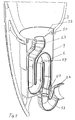
- FIG. 1 shows a urinal 1 which has a sanitary body 3, for example made of ceramic, of which only the lower one Part is shown.
- the basin 7 has one in its bottom preferably circular opening 10 into which a drain fitting 2 is inserted.
- This has a siphon 6, which is in a Open cup-shaped housing 9 is used and the an inlet 23 at an upper end and one at a lower end Has outlet 20.
- the siphon 6 is S-shaped as usual wound and has an overflow edge 14, in front of which Barrier water 15 forms.
- the inlet 23 of the siphon 6 is by means of a detachable plug connection 24 (Fig. 2) with a tubular nozzle 22 one Inlet funnel 12 connected, which has an upper opening 8.
- the plug connection 24 can also by an inseparable connection to be replaced.
- the inlet funnel 12 be welded to the siphon 6.
- the inlet funnel 12 is inserted from above into the housing 9 and with a sealing ring 11 sealed against this.
- the inlet of the inlet funnel 12 can be covered with a cap 28 as a privacy screen.
- the outlet 20 of the siphon 6 is plug-shaped and into one corresponding recess 16 in the bottom 27 of the housing 9 detachable used.
- a sealing ring 19 seals the outlet from the housing 9.
- the outlet 20 of the siphon 6 is from above inserted into the recess 16 and can be locked in this his.
- the recess 16 is open at the bottom and leads to a drain arch 17, which is attached to the housing 6 and a nozzle 26, which is aligned horizontally and on a drain line 4 is connected.
- the flow sheet 17 can be fixed with the Housing 9 connected, for example welded.
- the drain pipe 17 is joined blind.
- the drain arch 17 is designed so that it is a so-called Forms sump 18, which narrows the air passage without that the cross-section is reduced.
- the swamp 18 increased the suction effect of the siphon 6 in a manner known per se.
- the drain fitting 2 can thus with very little or even without Water can be used.
- the siphon 6 is in a lower region of the cup 9 by means of vertically extending ribs 25 for installation and removal guided.
- the siphon 6 can be used together with the inlet funnel 12 be lifted out of the housing. Is the inlet funnel 12 detachably connected to the siphon 6, so the inlet funnel 12 can also be lifted up separately. Then you can then the siphon 6 can be removed from the housing 9.
- the Drain elbow 18 and the drain pipe are now accessible from above and can be cleaned if necessary or objects be removed from this. After cleaning the siphon 6 and the inlet funnel 12, these are again from above inserted into the housing 9.
- the siphon 6 is as explained guided here on the guide ribs 25. Tools are with Installation and removal not required.
- the Housing 9 can be inexpensive as a simple molded body made of plastic getting produced. At the top of the housing 9 is a molded outwardly projecting collar 21, which at the opening 10 the sanitary body 3 is supported. The housing 9 is from below inserted into the opening 11 and can be locked in this or otherwise be fixed. Basically, the case could also 9 be designed so that it can be installed and removed from above is.
Abstract
Description
Die Erfindung betrifft eine Ablaufarmatur für eine Sanitärvorrichtung, insbesondere Klosetts und Urinal, mit einem Siphon, der einen Geruchsverschluss bildet und einen Einlass aufweist, der an eine Ablauföffnung eines Sanitärkörpers anzuschliessen ist und der einen Ausgang aufweist, welcher mit einer Ablaufleitung zu verbinden ist. Ablaufarmaturen der genannten Art sind in der Sanitärtechnik beispielsweise bei Spülbecken und Urinalen allgemein bekannt. Bei einem Urinal beispielsweise gelangt Spülwasser durch die Ablauföffnung in den Siphon und schliesslich in die Ablaufleitung. Im Siphon ist bis zu einem Überlauf Sperrwasser vorhanden, das einen Geruchsverschluss bildet, der verhindern soll, dass Gase aus der Ablaufleitung in den Sanitärkörper austreten können. Besonders bei Urinalen und Trennklosetts bei hoher Frequentierung ist die erforderliche regelmässige Reinigung und Wartung der Ablaufgarnitur vergleichsweise aufwendig. Verstopfungen des Siphons und der Ablaufleitung, die relativ häufig sind, führen zu Ausfällen und zu einem aufwendigen Ausbau des Siphons.The invention relates to a drain fitting for a sanitary device, especially toilets and urinals, with a siphon, which forms an odor trap and has an inlet, to connect to a drain opening of a sanitary body and which has an output which has a drain line is to be connected. Drain fittings of the type mentioned are in sanitary engineering, for example in sinks and urinals well known. In a urinal, for example, rinse water gets into it through the drain opening in the siphon and finally in the drain pipe. There is sealing water in the siphon up to an overflow present, which forms an odor trap that prevent that gases from the drain pipe into the sanitary body can exit. Especially with urinals and separation toilets high traffic is the required regular cleaning and maintenance of the waste set is comparatively complex. Blockages in the siphon and drain line, the relative are frequent, lead to failures and costly expansion of the siphon.
Der Erfindung liegt die Aufgabe zugrunde, eine Ablaufarmatur der genannten Art zu schaffen, die sich insbesondere für Urinalanlagen eignet und bei denen die Reinigung und Wartung vereinfacht ist. Die Ablaufarmatur soll trotzdem funktionssicher sein.The invention has for its object a drain valve to create mentioned type, which is particularly suitable for urinal systems suitable and for which cleaning and maintenance are simplified is. The drain fitting should still be reliable.
Die Aufgabe ist bei einer gattungsgemässen Ablaufgarnitur dadurch gelöst, dass der Siphon von oben in die Ablauföffnung des Sanitärkörpers einsetzbar und nach oben aus dieser ausbaubar ist. Bei der erfindungsgemässen Ablaufarmatur ist der Siphon nicht wie bisher üblich von unten an einen nach unten ragenden Stutzen der Ablauföffnung angesetzt, sondern von oben eingesetzt. Zur Reinigung der Ablaufarmatur und der Ablaufleitung wird der Siphon in einfacher Weise von oben ausgebaut und kann dann gereinigt oder ersetzt werden. Der Sanitärkörper muss hierbei nicht von der Wand abgenommen werden. Ein nicht mehr funktionstüchtiger Siphon kann in einfacher Weise durch einen neuen Siphon ersetzt werden. Zudem ist damit eine bessere Zugänglichkeit zur Ablaufleitung gewährleistet.The task is with a generic waste set solved that the siphon from above into the drain opening of the Sanitary body can be used and removed from this upwards is. In the drain fitting according to the invention is the siphon not, as usual, from the bottom to the bottom The outlet opening is attached, but inserted from above. For cleaning the drain fitting and the drain pipe the siphon can be easily removed from above then cleaned or replaced. The sanitary unit must do this cannot be removed from the wall. A no longer functional Siphon can be easily replaced by a new one Siphon to be replaced. It also means better accessibility guaranteed to drain line.
Nach einer Weiterbildung der Erfindung ist vorgesehen, dass der Siphon ein sogenannter Absaugesiphon ist, der die gleiche Wirkungsweise wie ein handelsüblicher Siphon hat.According to a development of the invention, it is provided that the Siphon is a so-called suction siphon, which works the same way like a commercial siphon.
Nach einer Weiterbildung der Erfindung ist vorgesehen, dass der Siphon in einem becherförmigen Gehäuse gelagert ist. Dieses Gehäuse befindet sich unterhalb der Ablauföffnung und nimmt den Siphon auf. Zum einfacheren Ein- und Ausbau des Siphons in das becherförmige Gehäuse ist vorgesehen, dass der Siphon in diesem becherförmigen Gehäuse geführt ist. Die Führung des Siphons im becherförmigen Gehäuse vereinfacht insbesondere den Einbau des Siphons und stellt sicher, dass dieser immer in der richtigen Lage eingebaut wird. Das becherförmige Gehäuse kann zudem als Messbecher für die Einstellung der Spülwassermenge dienen.According to a development of the invention, it is provided that the Siphon is stored in a cup-shaped housing. This housing is located below the drain opening and takes the Siphon on. For easier installation and removal of the siphon in the cup-shaped housing is provided that the siphon in this cup-shaped housing is guided. The guidance of the siphon in the cup-shaped housing in particular simplifies the installation of the Siphons and ensures that this is always in the correct one Location is installed. The cup-shaped housing can also be used as a Use measuring cups for setting the amount of rinse water.
Nach einer Weiterbildung der Erfindung ist vorgesehen, dass am Einlass des Siphons ein nach oben gerichteter Einlauftrichter angeordnet ist. Dieser Einlauftrichter kann fest oder lösbar mit dem Siphon verbunden sein. Ist dieser Einlauftrichter lösbar mit dem Siphon verbunden, so wird die Reinigung noch weiter vereinfacht und kann aus verschiedenen Materialien hergestellt werden. Der Siphon und der Einlauftrichter sind dann als einzelne Teile ausbaubar und reinigbar. Vorzugsweise ist der Einlass des Einlauftrichters noch mit einer hutförmigen Kappel abgedeckt.According to a development of the invention it is provided that on The inlet of the siphon is an upward inlet funnel is arranged. This inlet funnel can be fixed or detachable with be connected to the siphon. Is this inlet funnel detachable with connected to the siphon, cleaning is made even easier and can be made from different materials. The siphon and the inlet funnel are then separate parts removable and cleanable. The inlet of the inlet funnel is preferably still covered with a hat-shaped cap.
Nach einer Weiterbildung der Erfindung ist vorgesehen, dass am unteren Ende des Siphons ein Ablaufbogen angeschlossen ist, der einen sogenannten Sumpf bildet und welcher den Siphon mit der Ablaufleitung verbindet. Mit einem solchen Ablaufbogen kann die Absaugwirkung der Ablaufarmatur wesentlich erhöht werden. Dies hat den Vorteil, dass mit sehr wenig Wasser, z.B. 1 Liter, gespült werden kann. Damit kann somit Wasser gespart werden. Bei öffentlichen und sehr häufig benutzten Urinalen führt dies zu erheblichen Einsparungen. Der Ablaufbogen ist vorzugsweise lösbare mit dem Siphon verbunden. Beim Ausbau des Siphons bleibt somit der Ablaufbogen mit der Ablaufleitung verbunden. Bei ausgebautem Siphon ist der Ablaufbogen und die Ablaufleitung für eine Reinigung vergleichsweise gut zugänglich.According to a development of the invention it is provided that on a drain elbow is connected to the lower end of the siphon forms a so-called swamp and which forms the siphon with the Drain line connects. With such a flow sheet, the Suction effect of the drain fitting can be increased significantly. This has the advantage that with very little water, e.g. 1 liter, rinsed can be. Water can thus be saved. at this leads to public and very frequently used urinals significant savings. The drain arch is preferably detachable connected to the siphon. When removing the siphon remains thus the drain elbow is connected to the drain pipe. When removed Siphon is the drain elbow and the drain pipe for cleaning comparatively easily accessible.
Nach einer Weiterbildung der Erfindung ist der Auslass des Siphons stöpselförmig ausgebildet und lösbar in eine korrespondierende Vertiefung des Gehäuses eingesetzt. Der Siphon kann damit ohne Werkzeuge ein- und ausgebaut werden. Beim Einbau des Siphons wird der stöpselförmige Auslass in die entsprechende Vertiefung des Gehäuses eingesetzt. Eine solche Verbindung kann auch blind hergestellt werden.According to a development of the invention, the outlet of the siphon is plug-shaped and detachable into a corresponding one Depression of the housing used. The siphon can can be installed and removed without tools. When installing the siphon the plug-shaped outlet into the corresponding recess of the housing used. Such a connection can also be made blind.
Weitere vorteilhafte Merkmale ergeben sich aus den abhängigen Patenansprüchen der nachfolgenden Beschreibung sowie der Zeichnung.Further advantageous features result from the dependent ones Patent claims of the following description and the drawing.
Ein Ausführungsbeispiel der Erfindung wird nachfolgend anhand der Zeichnung näher erläutert. Es zeigen:
Figur 1- ein vertikaler Schnitt durch eine Sanitärvorrichtung mit einer erfindungsgemässen Ablaufarmatur,
Figur 2- ein vertikaler Schnitt durch eine erfindungsgemässe Ablaufarmatur und
Figur 3- eine weitere räumliche Ansicht einer geschnittenen Sanitärvorrichtung mit einer erfindungsgemässen Ablaufarmatur.
- Figure 1
- a vertical section through a sanitary device with a drain fitting according to the invention,
- Figure 2
- a vertical section through a drain fitting according to the invention and
- Figure 3
- a further spatial view of a sectioned sanitary device with a drain fitting according to the invention.
Die Figur 1 zeigt ein Urinal 1, das einen Sanitärkörper 3, beispielsweise
aus Keramik aufweist, von dem hier lediglich der untere
Teil gezeigt ist. Das Becken 7 weist in seinem Boden eine
vorzugsweise kreisrunde Öffnung 10 auf, in die eine Ablaufgarnitur
2 eingesetzt ist. Diese besitzt einen Siphon 6, der in ein
oben offenes becherförmiges Gehäuse 9 eingesetzt ist und der an
einem oberen Ende einen Einlass 23 und an einem unteren Ende einen
Auslass 20 aufweist. Der Siphon 6 ist wie üblich S-förmig
gewunden und weist eine Überlaufkante 14 auf, vor welcher sich
Sperrwasser 15 bildet.FIG. 1 shows a urinal 1 which has a
Der Einlass 23 des Siphons 6 ist mittels einer lösbaren Steckverbindung
24 (Fig. 2) mit einem rohrförmigen Stutzen 22 eines
Einlauftrichters 12 verbunden, der eine obere Öffnung 8 besitzt.
Die Steckverbindung 24 kann aber auch durch eine unlösbare Verbindung
ersetzt sein. Beispielsweise kann der Einlauftrichter 12
mit dem Siphon 6 verschweisst sein. Der Einlauftrichter 12 ist
von oben in das Gehäuse 9 eingesetzt und mit einem Dichtungsring
11 gegen dieses abgedichtet. Der Einlass des Einlauftrichters 12
kann mit einer Kappe 28 als Sichtschutz abgedeckt sein. Der Auslass
20 des Siphons 6 ist stöpselförmig ausgebildet und in eine
korrespondierende Vertiefung 16 im Boden 27 des Gehäuses 9 lösbar
eingesetzt. Ein Dichtungsring 19 dichtet den Auslass gegenüber
dem Gehäuse 9 ab. Der Auslass 20 des Siphons 6 ist von oben
in die Vertiefung 16 eingesetzt und kann in dieser verrastet
sein. Die Vertiefung 16 ist unten offen und führt zu einem Ablaufbogen
17, der am Gehäuse 6 befestigt und der einen Stutzen
26 aufweist, der horizontal ausgerichtet und an einer Ablaufleitung
4 angeschlossen ist. Der Ablaufbogen 17 kann fest mit dem
Gehäuse 9 verbunden, beispielsweise verschweisst sein. Bei der
Montage des Sanitärkörpers 3 wird der Ablaufstutzen 17 blind gefügt.
Der Ablaufbogen 17 ist so ausgebildet, dass er einen sogenannten
Sumpf 18 bildet, welcher den Luftdurchlass verengt, ohne
dass hierbei der Querschnitt verkleinert wird. Der Sumpf 18 erhöht
in an sich bekannter Weise die Absaugwirkung des Siphons 6.
Die Ablaufarmatur 2 kann damit mit sehr wenig oder sogar ohne
Wasser verwendet werden.The
Der Siphon 6 ist in einem unteren Bereich des Bechers 9 mittels
vertikal sich erstreckender Rippen 25 für den Ein- und Ausbau
geführt. Der Siphon 6 kann zusammen mit dem Einlauftrichter 12
aus dem Gehäuse herausgehoben werden. Ist der Einlauftrichter 12
lösbar mit dem Siphon 6 verbunden, so kann der Einlauftrichter
12 auch separat nach oben ausgehoben werden. Anschliessend kann
dann der Siphon 6 aus dem Gehäuse 9 herausgenommen werden. Der
Ablaufbogen 18 sowie die Ablaufleitung sind nun von oben zugänglich
und können gegebenenfalls gereinigt oder es können Gegenstände
aus diesem entfernt werden. Nach einer Reinigung des Siphons
6 und des Einlauftrichters 12 werden diese wieder von oben
in das Gehäuse 9 eingesetzt. Der Siphon 6 ist wie erläutert
hierbei an den Führungsrippen 25 geführt. Werkzeuge sind beim
Ein- und Ausbau nicht erforderlich. Nach dem Einbau wird das
Becken 7 gespült und dadurch bildet sich im Siphon 6 durch das
Sperrwasser 15 wieder ein Geruchsverschluss. Gleichzeitig wird
hierbei im Ablaufbogen 17 mit Wasser der Sumpf 18 gebildet. Das
Urinal 1 ist dann bereits wieder für den Gebrauch bereit. Das
Gehäuse 9 kann als einfacher Formkörper kostengünstig aus Kunststoff
hergestellt werden. Am oberen Rand des Gehäuses 9 ist ein
nach aussen ragender Kragen 21 angeformt, der an der Öffnung 10
des Sanitärkörpers 3 abgestützt ist. Das Gehäuse 9 wird von unten
in die Öffnung 11 eingesetzt und kann in dieser verrastet
oder sonstwie fixiert sein. Grundsätzlich könnte auch das Gehäuse
9 so ausgebildet sein, dass es von oben ein- und ausbaubar
ist.The siphon 6 is in a lower region of the
Claims (13)
Priority Applications (4)
| Application Number | Priority Date | Filing Date | Title |
|---|---|---|---|
| EP02405100A EP1335076B1 (en) | 2002-02-11 | 2002-02-11 | Outlet fitting for a sanitary device, in particular a urinal |
| AT02405100T ATE296923T1 (en) | 2002-02-11 | 2002-02-11 | DRAIN FITTING FOR A SANITARY DEVICE, PARTICULARLY URINAL |
| DE50203264T DE50203264D1 (en) | 2002-02-11 | 2002-02-11 | Drain fitting for a sanitary device, in particular urinal |
| US10/361,461 US6757918B2 (en) | 2002-02-11 | 2003-02-10 | Waste outlet fitting for a sanitary appliance, in particular a urinal |
Applications Claiming Priority (1)
| Application Number | Priority Date | Filing Date | Title |
|---|---|---|---|
| EP02405100A EP1335076B1 (en) | 2002-02-11 | 2002-02-11 | Outlet fitting for a sanitary device, in particular a urinal |
Publications (2)
| Publication Number | Publication Date |
|---|---|
| EP1335076A1 true EP1335076A1 (en) | 2003-08-13 |
| EP1335076B1 EP1335076B1 (en) | 2005-06-01 |
Family
ID=27589199
Family Applications (1)
| Application Number | Title | Priority Date | Filing Date |
|---|---|---|---|
| EP02405100A Expired - Lifetime EP1335076B1 (en) | 2002-02-11 | 2002-02-11 | Outlet fitting for a sanitary device, in particular a urinal |
Country Status (4)
| Country | Link |
|---|---|
| US (1) | US6757918B2 (en) |
| EP (1) | EP1335076B1 (en) |
| AT (1) | ATE296923T1 (en) |
| DE (1) | DE50203264D1 (en) |
Cited By (5)
| Publication number | Priority date | Publication date | Assignee | Title |
|---|---|---|---|---|
| DE202004013127U1 (en) * | 2004-08-20 | 2006-01-05 | Viega Gmbh & Co. Kg | Odor trap for a drain |
| WO2007038809A1 (en) * | 2005-09-27 | 2007-04-05 | Johannes Cronje | A plumbing connection hub |
| DE102009011061B3 (en) * | 2009-03-02 | 2010-12-16 | Urimat Holding Ag | Auxiliary device for hygienic removal and disposal of stink trap or cover part, comprises handling device which has gripper device at its one end, where pouch is held at base with gripper device |
| WO2018197026A1 (en) * | 2016-06-21 | 2018-11-01 | Geberit International Ag | Siphon |
| EP3421676A1 (en) * | 2017-06-27 | 2019-01-02 | uridan waterless solutions GmbH | Odour seal element for installation in a drain, in particular the drain of a waterless urinal |
Families Citing this family (7)
| Publication number | Priority date | Publication date | Assignee | Title |
|---|---|---|---|---|
| FR2924785B1 (en) * | 2007-12-05 | 2012-02-24 | Sanitaire Accessoires Services S A S | DEVICE FOR CONNECTING PIPES FOR SIPHON |
| GB2459915B (en) * | 2008-03-06 | 2013-01-30 | Mark David Marston | Removable access trap |
| US8321967B2 (en) | 2008-08-01 | 2012-12-04 | Kohler Co. | Wall installed toilet |
| US20120233753A1 (en) * | 2011-03-16 | 2012-09-20 | Andreas Baer | Waterless Urinal Conversion Assembly |
| DE102012104325B3 (en) | 2012-05-18 | 2013-11-21 | Viega Gmbh & Co. Kg | Drain fitting for a drainage basin, in particular a urinal, with a siphoning siphon |
| US11111663B2 (en) | 2017-09-15 | 2021-09-07 | Kohler Co. | Urinal with trapway connection system |
| WO2019185813A1 (en) * | 2018-03-29 | 2019-10-03 | Geberit International Ag | Siphon |
Citations (5)
| Publication number | Priority date | Publication date | Assignee | Title |
|---|---|---|---|---|
| DE2447695A1 (en) * | 1974-10-07 | 1976-04-08 | Franz Viegener Ii Armaturenfab | Compact odour trap with suction device for urinals - is integral plastics unit inserted into housing (NL090476) |
| FR2423595A1 (en) * | 1978-04-17 | 1979-11-16 | Ernst F Ing Ag | INTERCHANGEABLE DISPOSABLE SIPHON FOR PUBLIC URINALS |
| DE19739077A1 (en) * | 1997-09-08 | 1999-03-11 | Maris Murins | Collector trough for floor-drain |
| DE20009443U1 (en) * | 2000-05-25 | 2000-12-14 | Striedacher Franz | Drain device, in particular for wash basins, sinks or the like. |
| US20020000246A1 (en) * | 2000-06-30 | 2002-01-03 | Geberit Technik Ag | Suction-type siphon for a flushing device |
Family Cites Families (6)
| Publication number | Priority date | Publication date | Assignee | Title |
|---|---|---|---|---|
| US766764A (en) * | 1903-05-28 | 1904-08-02 | John E Keyt | Water-seal trap. |
| US4403355A (en) * | 1980-08-05 | 1983-09-13 | Elbert L. Petty | Bathtub drain enclosure |
| EP0467827B1 (en) * | 1990-07-20 | 1993-12-15 | Geberit AG | Drain connection on a sanitary element |
| GB9716498D0 (en) * | 1997-08-04 | 1997-10-08 | Mitchell Geoffrey J | Apparatus |
| US6269495B1 (en) * | 2000-06-06 | 2001-08-07 | C&D Innovations, L.C. | Adjustable floor drain apparatus |
| EP1247910B1 (en) * | 2001-04-06 | 2009-04-08 | Geberit Technik Ag | Odour-trap for waterless urinal |
-
2002
- 2002-02-11 EP EP02405100A patent/EP1335076B1/en not_active Expired - Lifetime
- 2002-02-11 AT AT02405100T patent/ATE296923T1/en active
- 2002-02-11 DE DE50203264T patent/DE50203264D1/en not_active Expired - Lifetime
-
2003
- 2003-02-10 US US10/361,461 patent/US6757918B2/en not_active Expired - Fee Related
Patent Citations (5)
| Publication number | Priority date | Publication date | Assignee | Title |
|---|---|---|---|---|
| DE2447695A1 (en) * | 1974-10-07 | 1976-04-08 | Franz Viegener Ii Armaturenfab | Compact odour trap with suction device for urinals - is integral plastics unit inserted into housing (NL090476) |
| FR2423595A1 (en) * | 1978-04-17 | 1979-11-16 | Ernst F Ing Ag | INTERCHANGEABLE DISPOSABLE SIPHON FOR PUBLIC URINALS |
| DE19739077A1 (en) * | 1997-09-08 | 1999-03-11 | Maris Murins | Collector trough for floor-drain |
| DE20009443U1 (en) * | 2000-05-25 | 2000-12-14 | Striedacher Franz | Drain device, in particular for wash basins, sinks or the like. |
| US20020000246A1 (en) * | 2000-06-30 | 2002-01-03 | Geberit Technik Ag | Suction-type siphon for a flushing device |
Cited By (7)
| Publication number | Priority date | Publication date | Assignee | Title |
|---|---|---|---|---|
| DE202004013127U1 (en) * | 2004-08-20 | 2006-01-05 | Viega Gmbh & Co. Kg | Odor trap for a drain |
| WO2007038809A1 (en) * | 2005-09-27 | 2007-04-05 | Johannes Cronje | A plumbing connection hub |
| DE102009011061B3 (en) * | 2009-03-02 | 2010-12-16 | Urimat Holding Ag | Auxiliary device for hygienic removal and disposal of stink trap or cover part, comprises handling device which has gripper device at its one end, where pouch is held at base with gripper device |
| WO2018197026A1 (en) * | 2016-06-21 | 2018-11-01 | Geberit International Ag | Siphon |
| US11280076B2 (en) | 2016-06-21 | 2022-03-22 | Geberit International Ag | Siphon |
| EP3421676A1 (en) * | 2017-06-27 | 2019-01-02 | uridan waterless solutions GmbH | Odour seal element for installation in a drain, in particular the drain of a waterless urinal |
| WO2019002332A1 (en) * | 2017-06-27 | 2019-01-03 | Uridan Waterless Solutions Gmbh | Odour trap element for installation in an outflow, in particular in the outflow of a waterless urinal |
Also Published As
| Publication number | Publication date |
|---|---|
| DE50203264D1 (en) | 2005-07-07 |
| US6757918B2 (en) | 2004-07-06 |
| EP1335076B1 (en) | 2005-06-01 |
| ATE296923T1 (en) | 2005-06-15 |
| US20030150051A1 (en) | 2003-08-14 |
Similar Documents
| Publication | Publication Date | Title |
|---|---|---|
| EP2045403B1 (en) | Outlet fitting with integrated overflow | |
| EP2009187B1 (en) | Sanitary facility with a floor drain and method for assembling such a sanitary facility | |
| EP2986787B1 (en) | Toilet with personal shower integrated into flushing water distributor | |
| EP1335076B1 (en) | Outlet fitting for a sanitary device, in particular a urinal | |
| EP1854926B1 (en) | Outlet device for a flushing cistern | |
| DE202006020903U1 (en) | Installation device for a sanitary device and sanitary device with such an installation device | |
| EP1447485B1 (en) | Draining device | |
| EP1775395A1 (en) | Draining device for sanitary installations | |
| DE102005036464B3 (en) | Anti-syphon/stench trap for drains on sanitary units has a casing with an inlet, a ring chamber, a drain chamber, a spiral inner wall and an overflow | |
| EP1862602B1 (en) | Basin with hidden overflow and corresponding waste fittings | |
| AT5032U1 (en) | SUCTION SIPHON FOR A RINSING DEVICE | |
| DE102006053756A1 (en) | Drainage armature for shower tub or bath tub, has separating wall arranged between interior and discharge nozzle, and limiting wall of interior connected with upper wall of housing in gas-tight manner and designed as single unit | |
| EP1544360A1 (en) | Drainage device | |
| EP2275610B1 (en) | Water cistern for a closet and corresponding closet | |
| EP1837447B1 (en) | Urinal | |
| EP1484453A1 (en) | Overflow and outlet device for sanitary apparatus | |
| DE10204683B4 (en) | pool | |
| EP1574629B1 (en) | Discharger armature for a sanitary apparatus, especially for a shower tray | |
| EP1614816B1 (en) | Overflow and outlet device for sanitary apparatus | |
| EP1075572B1 (en) | W.c. bowl | |
| DE102012211655A1 (en) | Shower toilet, has shower arm arranged in region of upper end of toilet bowl, and overflow aperture that is spaced from lowest point of shower arm when overflow aperture is inserted into interior space | |
| DE102009009077A1 (en) | Concealed bath mixer with an easily replaceable Amaturenblock, with integrated, flow-controlled, mechanical Rohrtrenner GB | |
| WO1997022761A1 (en) | Device for a cistern | |
| EP3421676B1 (en) | Odour seal element for installation in a drain, in particular the drain of a waterless urinal | |
| DE202015107000U1 (en) | drainage system |
Legal Events
| Date | Code | Title | Description |
|---|---|---|---|
| PUAI | Public reference made under article 153(3) epc to a published international application that has entered the european phase |
Free format text: ORIGINAL CODE: 0009012 |
|
| AK | Designated contracting states |
Designated state(s): AT BE CH CY DE DK ES FI FR GB GR IE IT LI LU MC NL PT SE TR |
|
| AX | Request for extension of the european patent |
Extension state: AL LT LV MK RO SI |
|
| 17P | Request for examination filed |
Effective date: 20030906 |
|
| 17Q | First examination report despatched |
Effective date: 20031125 |
|
| AKX | Designation fees paid |
Designated state(s): AT BE CH CY DE DK ES FI FR GB GR IE IT LI LU MC NL PT SE TR |
|
| GRAP | Despatch of communication of intention to grant a patent |
Free format text: ORIGINAL CODE: EPIDOSNIGR1 |
|
| GRAS | Grant fee paid |
Free format text: ORIGINAL CODE: EPIDOSNIGR3 |
|
| GRAA | (expected) grant |
Free format text: ORIGINAL CODE: 0009210 |
|
| RTI1 | Title (correction) |
Free format text: OUTLET FITTING FOR A SANITARY DEVICE, IN PARTICULAR A URINAL |
|
| AK | Designated contracting states |
Kind code of ref document: B1 Designated state(s): AT BE CH CY DE DK ES FI FR GB GR IE IT LI LU MC NL PT SE TR |
|
| PG25 | Lapsed in a contracting state [announced via postgrant information from national office to epo] |
Ref country code: FI Free format text: LAPSE BECAUSE OF FAILURE TO SUBMIT A TRANSLATION OF THE DESCRIPTION OR TO PAY THE FEE WITHIN THE PRESCRIBED TIME-LIMIT Effective date: 20050601 Ref country code: IE Free format text: LAPSE BECAUSE OF FAILURE TO SUBMIT A TRANSLATION OF THE DESCRIPTION OR TO PAY THE FEE WITHIN THE PRESCRIBED TIME-LIMIT Effective date: 20050601 |
|
| REG | Reference to a national code |
Ref country code: GB Ref legal event code: FG4D Free format text: NOT ENGLISH |
|
| REG | Reference to a national code |
Ref country code: CH Ref legal event code: EP Ref country code: CH Ref legal event code: NV Representative=s name: ISLER & PEDRAZZINI AG |
|
| GBT | Gb: translation of ep patent filed (gb section 77(6)(a)/1977) |
Effective date: 20050602 |
|
| REF | Corresponds to: |
Ref document number: 50203264 Country of ref document: DE Date of ref document: 20050707 Kind code of ref document: P |
|
| REG | Reference to a national code |
Ref country code: IE Ref legal event code: FG4D Free format text: LANGUAGE OF EP DOCUMENT: GERMAN |
|
| PG25 | Lapsed in a contracting state [announced via postgrant information from national office to epo] |
Ref country code: GR Free format text: LAPSE BECAUSE OF FAILURE TO SUBMIT A TRANSLATION OF THE DESCRIPTION OR TO PAY THE FEE WITHIN THE PRESCRIBED TIME-LIMIT Effective date: 20050901 Ref country code: DK Free format text: LAPSE BECAUSE OF FAILURE TO SUBMIT A TRANSLATION OF THE DESCRIPTION OR TO PAY THE FEE WITHIN THE PRESCRIBED TIME-LIMIT Effective date: 20050901 Ref country code: SE Free format text: LAPSE BECAUSE OF FAILURE TO SUBMIT A TRANSLATION OF THE DESCRIPTION OR TO PAY THE FEE WITHIN THE PRESCRIBED TIME-LIMIT Effective date: 20050901 |
|
| PG25 | Lapsed in a contracting state [announced via postgrant information from national office to epo] |
Ref country code: PT Free format text: LAPSE BECAUSE OF FAILURE TO SUBMIT A TRANSLATION OF THE DESCRIPTION OR TO PAY THE FEE WITHIN THE PRESCRIBED TIME-LIMIT Effective date: 20051103 |
|
| REG | Reference to a national code |
Ref country code: IE Ref legal event code: FD4D |
|
| PG25 | Lapsed in a contracting state [announced via postgrant information from national office to epo] |
Ref country code: MC Free format text: LAPSE BECAUSE OF NON-PAYMENT OF DUE FEES Effective date: 20060228 Ref country code: LU Free format text: LAPSE BECAUSE OF NON-PAYMENT OF DUE FEES Effective date: 20060228 |
|
| PLBE | No opposition filed within time limit |
Free format text: ORIGINAL CODE: 0009261 |
|
| STAA | Information on the status of an ep patent application or granted ep patent |
Free format text: STATUS: NO OPPOSITION FILED WITHIN TIME LIMIT |
|
| ET | Fr: translation filed | ||
| 26N | No opposition filed |
Effective date: 20060302 |
|
| REG | Reference to a national code |
Ref country code: CH Ref legal event code: PCAR Free format text: ISLER & PEDRAZZINI AG;POSTFACH 1772;8027 ZUERICH (CH) |
|
| PG25 | Lapsed in a contracting state [announced via postgrant information from national office to epo] |
Ref country code: TR Free format text: LAPSE BECAUSE OF FAILURE TO SUBMIT A TRANSLATION OF THE DESCRIPTION OR TO PAY THE FEE WITHIN THE PRESCRIBED TIME-LIMIT Effective date: 20050601 |
|
| PG25 | Lapsed in a contracting state [announced via postgrant information from national office to epo] |
Ref country code: CY Free format text: LAPSE BECAUSE OF FAILURE TO SUBMIT A TRANSLATION OF THE DESCRIPTION OR TO PAY THE FEE WITHIN THE PRESCRIBED TIME-LIMIT Effective date: 20050601 |
|
| PG25 | Lapsed in a contracting state [announced via postgrant information from national office to epo] |
Ref country code: ES Free format text: LAPSE BECAUSE OF NON-PAYMENT OF DUE FEES Effective date: 20060228 |
|
| REG | Reference to a national code |
Ref country code: CH Ref legal event code: PUE Owner name: GEBERIT INTERNATIONAL AG Free format text: GEBERIT TECHNIK AG#SCHACHENSTRASSE 77#8645 JONA (CH) -TRANSFER TO- GEBERIT INTERNATIONAL AG#SCHACHENSTRASSE 77#8645 JONA (CH) |
|
| PGFP | Annual fee paid to national office [announced via postgrant information from national office to epo] |
Ref country code: FR Payment date: 20100226 Year of fee payment: 9 Ref country code: IT Payment date: 20100225 Year of fee payment: 9 |
|
| PGFP | Annual fee paid to national office [announced via postgrant information from national office to epo] |
Ref country code: GB Payment date: 20100218 Year of fee payment: 9 |
|
| PGFP | Annual fee paid to national office [announced via postgrant information from national office to epo] |
Ref country code: NL Payment date: 20100215 Year of fee payment: 9 |
|
| PGFP | Annual fee paid to national office [announced via postgrant information from national office to epo] |
Ref country code: BE Payment date: 20100401 Year of fee payment: 9 |
|
| BERE | Be: lapsed |
Owner name: *GEBERIT TECHNIK A.G. Effective date: 20110228 |
|
| REG | Reference to a national code |
Ref country code: NL Ref legal event code: V1 Effective date: 20110901 |
|
| GBPC | Gb: european patent ceased through non-payment of renewal fee |
Effective date: 20110211 |
|
| REG | Reference to a national code |
Ref country code: FR Ref legal event code: ST Effective date: 20111102 |
|
| PG25 | Lapsed in a contracting state [announced via postgrant information from national office to epo] |
Ref country code: BE Free format text: LAPSE BECAUSE OF NON-PAYMENT OF DUE FEES Effective date: 20110228 |
|
| PG25 | Lapsed in a contracting state [announced via postgrant information from national office to epo] |
Ref country code: NL Free format text: LAPSE BECAUSE OF NON-PAYMENT OF DUE FEES Effective date: 20110901 Ref country code: IT Free format text: LAPSE BECAUSE OF NON-PAYMENT OF DUE FEES Effective date: 20110211 |
|
| PG25 | Lapsed in a contracting state [announced via postgrant information from national office to epo] |
Ref country code: FR Free format text: LAPSE BECAUSE OF NON-PAYMENT OF DUE FEES Effective date: 20110228 |
|
| PG25 | Lapsed in a contracting state [announced via postgrant information from national office to epo] |
Ref country code: GB Free format text: LAPSE BECAUSE OF NON-PAYMENT OF DUE FEES Effective date: 20110211 |
|
| REG | Reference to a national code |
Ref country code: DE Ref legal event code: R082 Ref document number: 50203264 Country of ref document: DE Representative=s name: HOEGER, STELLRECHT & PARTNER PATENTANWAELTE, DE Ref country code: DE Ref legal event code: R082 Ref document number: 50203264 Country of ref document: DE Representative=s name: HOEGER, STELLRECHT & PARTNER PATENTANWAELTE MB, DE |
|
| REG | Reference to a national code |
Ref country code: DE Ref legal event code: R082 Ref document number: 50203264 Country of ref document: DE Representative=s name: HOEGER, STELLRECHT & PARTNER PATENTANWAELTE MB, DE |
|
| PGFP | Annual fee paid to national office [announced via postgrant information from national office to epo] |
Ref country code: DE Payment date: 20180219 Year of fee payment: 17 Ref country code: CH Payment date: 20180212 Year of fee payment: 17 |
|
| PGFP | Annual fee paid to national office [announced via postgrant information from national office to epo] |
Ref country code: AT Payment date: 20180219 Year of fee payment: 17 |
|
| REG | Reference to a national code |
Ref country code: DE Ref legal event code: R082 Ref document number: 50203264 Country of ref document: DE Representative=s name: HOEGER, STELLRECHT & PARTNER PATENTANWAELTE MB, DE |
|
| REG | Reference to a national code |
Ref country code: DE Ref legal event code: R119 Ref document number: 50203264 Country of ref document: DE |
|
| REG | Reference to a national code |
Ref country code: CH Ref legal event code: PL |
|
| REG | Reference to a national code |
Ref country code: AT Ref legal event code: MM01 Ref document number: 296923 Country of ref document: AT Kind code of ref document: T Effective date: 20190211 |
|
| PG25 | Lapsed in a contracting state [announced via postgrant information from national office to epo] |
Ref country code: CH Free format text: LAPSE BECAUSE OF NON-PAYMENT OF DUE FEES Effective date: 20190228 Ref country code: AT Free format text: LAPSE BECAUSE OF NON-PAYMENT OF DUE FEES Effective date: 20190211 Ref country code: LI Free format text: LAPSE BECAUSE OF NON-PAYMENT OF DUE FEES Effective date: 20190228 |
|
| PG25 | Lapsed in a contracting state [announced via postgrant information from national office to epo] |
Ref country code: DE Free format text: LAPSE BECAUSE OF NON-PAYMENT OF DUE FEES Effective date: 20190903 |