EP1334856A2 - A mechanism for opening a gull-wing side door of a motor vehicle - Google Patents
A mechanism for opening a gull-wing side door of a motor vehicle Download PDFInfo
- Publication number
- EP1334856A2 EP1334856A2 EP03002297A EP03002297A EP1334856A2 EP 1334856 A2 EP1334856 A2 EP 1334856A2 EP 03002297 A EP03002297 A EP 03002297A EP 03002297 A EP03002297 A EP 03002297A EP 1334856 A2 EP1334856 A2 EP 1334856A2
- Authority
- EP
- European Patent Office
- Prior art keywords
- axis
- door
- rotation
- hinge
- vehicle
- Prior art date
- Legal status (The legal status is an assumption and is not a legal conclusion. Google has not performed a legal analysis and makes no representation as to the accuracy of the status listed.)
- Granted
Links
Images


Classifications
-
- B—PERFORMING OPERATIONS; TRANSPORTING
- B60—VEHICLES IN GENERAL
- B60J—WINDOWS, WINDSCREENS, NON-FIXED ROOFS, DOORS, OR SIMILAR DEVICES FOR VEHICLES; REMOVABLE EXTERNAL PROTECTIVE COVERINGS SPECIALLY ADAPTED FOR VEHICLES
- B60J5/00—Doors
- B60J5/04—Doors arranged at the vehicle sides
- B60J5/047—Doors arranged at the vehicle sides characterised by the opening or closing movement
- B60J5/0472—Doors arranged at the vehicle sides characterised by the opening or closing movement the door having a hinge axis in horizontal direction transverse to vehicle longitudinal axis
-
- E—FIXED CONSTRUCTIONS
- E05—LOCKS; KEYS; WINDOW OR DOOR FITTINGS; SAFES
- E05D—HINGES OR SUSPENSION DEVICES FOR DOORS, WINDOWS OR WINGS
- E05D15/00—Suspension arrangements for wings
-
- E—FIXED CONSTRUCTIONS
- E05—LOCKS; KEYS; WINDOW OR DOOR FITTINGS; SAFES
- E05D—HINGES OR SUSPENSION DEVICES FOR DOORS, WINDOWS OR WINGS
- E05D3/00—Hinges with pins
- E05D3/06—Hinges with pins with two or more pins
- E05D3/10—Hinges with pins with two or more pins with non-parallel pins
-
- E—FIXED CONSTRUCTIONS
- E05—LOCKS; KEYS; WINDOW OR DOOR FITTINGS; SAFES
- E05F—DEVICES FOR MOVING WINGS INTO OPEN OR CLOSED POSITION; CHECKS FOR WINGS; WING FITTINGS NOT OTHERWISE PROVIDED FOR, CONCERNED WITH THE FUNCTIONING OF THE WING
- E05F1/00—Closers or openers for wings, not otherwise provided for in this subclass
- E05F1/08—Closers or openers for wings, not otherwise provided for in this subclass spring-actuated, e.g. for horizontally sliding wings
- E05F1/10—Closers or openers for wings, not otherwise provided for in this subclass spring-actuated, e.g. for horizontally sliding wings for swinging wings, e.g. counterbalance
- E05F1/1091—Closers or openers for wings, not otherwise provided for in this subclass spring-actuated, e.g. for horizontally sliding wings for swinging wings, e.g. counterbalance with a gas spring
-
- E—FIXED CONSTRUCTIONS
- E05—LOCKS; KEYS; WINDOW OR DOOR FITTINGS; SAFES
- E05Y—INDEXING SCHEME RELATING TO HINGES OR OTHER SUSPENSION DEVICES FOR DOORS, WINDOWS OR WINGS AND DEVICES FOR MOVING WINGS INTO OPEN OR CLOSED POSITION, CHECKS FOR WINGS AND WING FITTINGS NOT OTHERWISE PROVIDED FOR, CONCERNED WITH THE FUNCTIONING OF THE WING
- E05Y2900/00—Application of doors, windows, wings or fittings thereof
- E05Y2900/50—Application of doors, windows, wings or fittings thereof for vehicles
- E05Y2900/53—Application of doors, windows, wings or fittings thereof for vehicles characterised by the type of wing
- E05Y2900/531—Doors
Definitions
- the present invention refers to a mechanism for opening and closing a gull-wing side door of a motor vehicle.
- a motor-vehicle side door 1 is hinged to the vehicle structure for rotation about a horizontal axis 2 arranged nearly in front of the door pillar 3 and inclined rearwards about 15 degrees (angle a) to the transverse direction, that is, to a direction perpendicular to the driving direction (in accordance with the convention usually adopted in the automotive industry).
- a hinge axis close to a front lower portion of the door is particularly advantageous from an ergonomic point of view, since it enables to reduce the space taken by the door in the open position and enlarge accordingly the space available for entering in or exiting from the passenger compartment.
- the hinge axis 2 of the door is inclined to the transverse direction whereby the door shifts laterally outwards while being opened.
- the invention is based on the idea of providing a mechanism for opening and closing a gull-wing side door of a motor vehicle which is arranged to move the door simultaneously upwards, by rotation about a substantially horizontal and transverse axis, and outwards, as a result of a translation in a substantially lateral direction.
- the mechanism is mounted on a side member of the motor-vehicle structure in the vicinity of the front door pillar and acts on a front lower portion of the door frame, thus reducing the space taken by the door in the open position, as explained before in connection with the prior art.
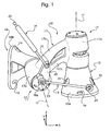
- a mechanism according to the invention is associated to a motor-vehicle side door 1 for moving the door 1 between a closed position C and an open position A.
- the mechanism 10 is mounted on a side member of the motor-vehicle structure (not shown) close to the front pillar of the respective door 1 and comprises basically a pair of hinges 11, 12, the axes of which neither lie in the same plane nor intersect each other, a rod 13 for connection between the two hinges 11, 12 and a gas spring 14.
- the first hinge 11 comprises:
- the arm 17 has also a second hollow cylindrical portion 17b the axis of which is indicated r2 and defines the axis of rotation for the second hinge 12.
- the second axis r2 which neither lies in the same plane as the first axis r1 nor intersects this latter, can rotate about the first axis r1 upon rotation of the movable arm 17.
- the second arm portion 17b is rigidly connected to the first portion 17a through an arcuate connecting portion 17c which runs nearly longitudinally.
- the second hinge 12 comprises:
- An end of the pin-like portion 18a of the second hinge 12 projecting from the hollow cylindrical portion 17b at the opposite side from the bracket-like portion 18b has a radially projecting extension 20 which provides a first point of articulation 21, spaced apart from the axis of rotation r2 of the portion 18a, for articulation of the gas spring 14.
- a second point of articulation 22 for the gas spring 14, on the other hand, is provided on a stationary portion of the vehicle (not shown), for example, on the front door pillar.
- the stationary body 15 of the first hinge 11 and the movable body 18 of the second hinge 12 are connected with each other by the connecting rod 13, the ends of which are engaged by a first articulation pin 23 projecting from the extension 20 and spaced from the axis r2, and by a second articulation pin 24 projecting from the base portion 15a.
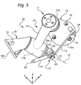
- the two pins 23 and 24 are arranged in such a manner that, with the door 1 in the closed position C, the rod 13 converges in plan view to the connecting portion 17c of the first hinge 11 towards the rear of the vehicle, as can be seen in Figure 3.
- the double-hinge mechanism 10 allows rotation about both the first axis r1, whereby the door is moved laterally outwards, and the second axis r2, whereby the door is shifted vertically upwards. While the axis r1 is held stationary with respect to the vehicle, the axis r2 is driven in rotation about the axis r1 as a single piece with the movable body 17. Due to its particular arrangement with respect to the parts constituting the two hinges 11, 12, the connecting rod 13 enables to combine the rotary movements about the two axes r1, r2 in such a manner that the mechanism 10 acts as an articulated quadrilateral mechanism in the three dimensions (not only in a plane). Therefore, the door only has to be either pulled laterally outwards or urged upwards to be opened, whereas it only has to be either pushed laterally inwards or urged downwards to be closed.
- the movable body 17 of the first hinge 11 is caused to rotate about the vertical axis r1.
- the rod 13 reacts as a pull-rod to rotation about the axis r1 and exerts through the pin 23 a clockwise torque (with respect to the view of Figure 1) about the axis r2 on the attachment portion 18 of the second hinge 12.
- the attachment portion 18 of the second hinge 12 and the door 1 attached thereto are caused to rotate upwards about the axis r2.
- the pulling action of the rod 13 is amplified by the extension of the gas spring 14, thereby ensuring that the exerted torque is strong enough to raise the door.
- the attachment portion 18 of the second hinge 12 rotates together with the door about the axis r2. Then, the rod 13 reacts as a push-rod to rotation about the axis r2, thereby forcing the movable body 17 of the first hinge 11 to rotate about the axis r1 towards the outside of the vehicle. In this case, also, the upwardly movement of the door is assisted by the extension of the gas spring 14, whereby the opening operation does not require a fine effort from the user.
- the door projects laterally outwards with respect to the closed position C and is inclined in a longitudinal vertical plane with its rear portion pointing upwards.
- the mechanism 10 is provided with means for adjusting the travel of the rotary movements about the both axes r1 and r2, in order to set the amount of lateral projection and inclination of the door in the open position A.
- the extension 20 of the second hinge 12 can be coupled with the pin-like portion 18a by means, for example, of a toothed joint (not shown) which enables adjustment of the angular position of the extension 20 relative respect to the bracket-like attachment portion 18b.
Abstract
Description
- The present invention refers to a mechanism for opening and closing a gull-wing side door of a motor vehicle.
- It is known for motor vehicles, particularly sport cars, the use of so-called gull-wing side doors, that is, side doors which can be opened upwards by rotation about a substantially horizontal axis.
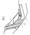
- A door of the type defined above is disclosed in German patent application DE 197 38 825, from which Figures 6 and 7 of the appended drawings are taken. With reference to these Figures, a motor-
vehicle side door 1 is hinged to the vehicle structure for rotation about ahorizontal axis 2 arranged nearly in front of thedoor pillar 3 and inclined rearwards about 15 degrees (angle a) to the transverse direction, that is, to a direction perpendicular to the driving direction (in accordance with the convention usually adopted in the automotive industry). The use of a hinge axis close to a front lower portion of the door is particularly advantageous from an ergonomic point of view, since it enables to reduce the space taken by the door in the open position and enlarge accordingly the space available for entering in or exiting from the passenger compartment. As can be clearly understood, in order to prevent the front part of the door frame from interfering with the motor-vehicle structure during the opening movement, thehinge axis 2 of the door is inclined to the transverse direction whereby the door shifts laterally outwards while being opened. - However, the arrangement provided in the above patent application requires a special shape of the door frame in the region where the door is hinged and thereby an accordingly larger lateral size of the vehicle, to the detriment of the aesthetic aspect thereof.
- It is the object of the present invention to provide an improved mechanism for opening and closing a gull-wing door of a motor vehicle with respect to the prior art discussed above, which is not affected by the problems discussed above and enables the driver or the passenger to easily enter in or exit from the vehicle.
- This object is fully achieved according to present invention by a mechanism as defined in
independent Claim 1. - In short, the invention is based on the idea of providing a mechanism for opening and closing a gull-wing side door of a motor vehicle which is arranged to move the door simultaneously upwards, by rotation about a substantially horizontal and transverse axis, and outwards, as a result of a translation in a substantially lateral direction. The mechanism is mounted on a side member of the motor-vehicle structure in the vicinity of the front door pillar and acts on a front lower portion of the door frame, thus reducing the space taken by the door in the open position, as explained before in connection with the prior art.
- Further characteristics of the invention will result from the following detailed description of a preferred embodiment thereof, given purely by way of non-limitative example, with reference to the appended drawings, in which:
- Figure 1 is a side perspective view from the inside of the vehicle of a mechanism for opening and closing a gull-wing left-hand side door according to the present invention, in a closed-door position;
- Figure 2 is a rear perspective view of the mechanism of Figure 1;
- Figure 3 is a perspective view from above of the mechanism of Figure 1;
- Figure 4 is a side view from the outside of the vehicle of a gull-wing door provided with a mechanism according to the present invention, showing a series of intermediate positions throughout the opening/closing movement of the door;
- Figure 5 is a similar view to that of Figure 4, from the inside of the vehicle;
- Figure 6 is a side view of a gull-wing door according to the prior art; and
- Figure 7 is a plan enlarged view, sectioned along line VII-VII, showing a detail of the gull-wing door of Figure 6,.
-
- In the description and claims which follow, terms such as "front" or "rear", "upper" or "lower", "longitudinal" or "transverse" are to be understood as referred to the mounted condition on the motor vehicle.
- With reference to Figures 1 to 5, in which parts and elements identical or corresponding to those of Figures 6 and 7 (prior art) have been given the same numbers, a mechanism according to the invention, generally indicated 10, is associated to a motor-
vehicle side door 1 for moving thedoor 1 between a closed position C and an open position A. - The
mechanism 10 is mounted on a side member of the motor-vehicle structure (not shown) close to the front pillar of therespective door 1 and comprises basically a pair ofhinges rod 13 for connection between the twohinges gas spring 14. - By referring now to Figures 1 to 3 in particular, the
first hinge 11 comprises: - a
stationary mounting body 15 having at its bottom abase portion 15a to be attached to the side member of the vehicle, for example, by means of a plurality of screws (not shown) inserted in a corresponding plurality of through-holes 16 provided in thebase portion 15a, and a verticalcylindrical pin 15b (Figure 2) at the top of thebase portion 15a, the axis of which is indicated r1 and defines the axis of rotation for thehinge 11; and - a movable arm, generally indicated 17, having a first
hollow
cylindrical portion 17a mounted coaxial on thepin 15b of thestationary body 15 for rotation about the axis r1. -
- The
arm 17 has also a second hollowcylindrical portion 17b the axis of which is indicated r2 and defines the axis of rotation for thesecond hinge 12. The second axis r2, which neither lies in the same plane as the first axis r1 nor intersects this latter, can rotate about the first axis r1 upon rotation of themovable arm 17. - As can be seen in particular in Figures 1 and 2, where a tern of three perpendicular axes is shown, of which a first axis x is orientated longitudinally towards the front of the vehicle, a second axis y is orientated transversely towards the outside of the vehicle and a third axis z is orientated vertically upwards, when the
door 1 is closed (position C) the axis of rotation r2 of thesecond hinge 12 is inclined upwards to a horizontal plane and rearwards to a transverse vertical plane. - The
second arm portion 17b is rigidly connected to thefirst portion 17a through an arcuate connectingportion 17c which runs nearly longitudinally. - The
second hinge 12 comprises: - the above-mentioned second hollow
cylindrical portion 17b of themovable arm 17 defining the axis of rotation r2 for the second hinge; and - a
movable body 18 comprising a cylindrical pin-like portion 18a (Figures 1 and 3) inserted into the hollowcylindrical portion 17b for rotation about the axis r2 and a bracket-like attachment portion 18b having, for example, a plurality ofholes 19 into which a corresponding plurality of screws (not shown) can be inserted for fixing that portion to the frame of thedoor 1. -
- An end of the pin-
like portion 18a of thesecond hinge 12 projecting from the hollowcylindrical portion 17b at the opposite side from the bracket-like portion 18b has a radially projectingextension 20 which provides a first point ofarticulation 21, spaced apart from the axis of rotation r2 of theportion 18a, for articulation of thegas spring 14. A second point ofarticulation 22 for thegas spring 14, on the other hand, is provided on a stationary portion of the vehicle (not shown), for example, on the front door pillar. - Finally, the
stationary body 15 of thefirst hinge 11 and themovable body 18 of thesecond hinge 12 are connected with each other by the connectingrod 13, the ends of which are engaged by afirst articulation pin 23 projecting from theextension 20 and spaced from the axis r2, and by asecond articulation pin 24 projecting from thebase portion 15a. The twopins door 1 in the closed position C, therod 13 converges in plan view to the connectingportion 17c of thefirst hinge 11 towards the rear of the vehicle, as can be seen in Figure 3. - The operation of the
mechanism 10 will be illustrated now by describing in detail only the opening movement of the side door 1 (that is, the movement from the closed position C to the open position A), the opposite movement being apparent in the light of the following description. - As explained before, the double-
hinge mechanism 10 allows rotation about both the first axis r1, whereby the door is moved laterally outwards, and the second axis r2, whereby the door is shifted vertically upwards. While the axis r1 is held stationary with respect to the vehicle, the axis r2 is driven in rotation about the axis r1 as a single piece with themovable body 17. Due to its particular arrangement with respect to the parts constituting the twohinges rod 13 enables to combine the rotary movements about the two axes r1, r2 in such a manner that themechanism 10 acts as an articulated quadrilateral mechanism in the three dimensions (not only in a plane). Therefore, the door only has to be either pulled laterally outwards or urged upwards to be opened, whereas it only has to be either pushed laterally inwards or urged downwards to be closed. - In case the door is pulled outwards, then the
movable body 17 of thefirst hinge 11 is caused to rotate about the vertical axis r1. As a result, therod 13 reacts as a pull-rod to rotation about the axis r1 and exerts through the pin 23 a clockwise torque (with respect to the view of Figure 1) about the axis r2 on theattachment portion 18 of thesecond hinge 12. As a result of the torque exerted by therod 13, theattachment portion 18 of thesecond hinge 12 and thedoor 1 attached thereto are caused to rotate upwards about the axis r2. The pulling action of therod 13 is amplified by the extension of thegas spring 14, thereby ensuring that the exerted torque is strong enough to raise the door. - In case the door is urged upwards, the
attachment portion 18 of thesecond hinge 12 rotates together with the door about the axis r2. Then, therod 13 reacts as a push-rod to rotation about the axis r2, thereby forcing themovable body 17 of thefirst hinge 11 to rotate about the axis r1 towards the outside of the vehicle. In this case, also, the upwardly movement of the door is assisted by the extension of thegas spring 14, whereby the opening operation does not require a fine effort from the user. - In the open position A (Figure 4) the door projects laterally outwards with respect to the closed position C and is inclined in a longitudinal vertical plane with its rear portion pointing upwards. Preferably, the
mechanism 10 is provided with means for adjusting the travel of the rotary movements about the both axes r1 and r2, in order to set the amount of lateral projection and inclination of the door in the open position A. To this end, theextension 20 of thesecond hinge 12 can be coupled with the pin-like portion 18a by means, for example, of a toothed joint (not shown) which enables adjustment of the angular position of theextension 20 relative respect to the bracket-like attachment portion 18b. Therefore, if theextension 20 is rotated clockwise, for example, starting from the position illustrated in Figure 1, then the assembly constituted by the pin-like portion 18a and theattachment portion 18b is allowed to rotate a smaller angle than before, and the inclination of the door in the open position A will be accordingly smaller. - Naturally, the principle of the invention remaining unchanged, embodiments and manufacturing details may vary widely from those described and illustrated purely by way of non-limitative example.
Claims (8)
- A mechanism for opening and closing a gull-wing side door (1) of a motor vehicle, of the type comprising a first hinge (11) defining a first axis of rotation (r1) stationary with respect to the vehicle structure, characterised in that it comprises alsoa second hinge (12) defining a second axis of rotation (r2) which neither lies in the same plane as the first axis (r1) nor intersects this latter, wherein the second axis (r2) is arranged to rotate about the first axis (r1) of the first hinge (11); andconnecting means (13) interposed between the two hinges (11, 12) for combining the rotary movements about their respective axes (r1, r2) so as to provide an articulated mechanism arranged to bring about the opening/closing movement of the door (1) by raising/lowering a rear part of the door (1) and, at the same time, by shifting laterally the door (1) towards the outside/inside of the vehicle.
- A mechanism according to Claim 1, of the type in which the first hinge (11) comprises a stationary body (15) connected to the vehicle structure and a movable arm (17) mounted on the stationary body (15) for rotation about the first axis (r1), and the second hinge (12) comprises a movable body (18), to which the door (1) is attached and which is arranged to rotate relative to the movable arm (17) about the second axis of rotation (r2); characterised in that said connecting means for combining the rotary movements of the two hinges (11, 12) about their respective axes (r1, r2) comprise a rod (13) having a first end articulated (24) to the stationary body (15) of the first hinge (11) and a second end articulated (23) to the movable body (18) of the second hinge (12) in a point spaced from the second axis of rotation (r2), whereby rotation of the movable body (18) relative to the movable arm (17) about the second axis (r2), in a direction such that the door (1) tends to rise/lower, causes the movable arm (17) to rotate relative to the stationary body (15) about the first axis (r1), thereby shifting laterally the door (1) towards the outside/inside of the vehicle.
- A mechanism according to Claim 2, characterised in that the stationary body (15) of the first hinge (11) has a cylindrical portion (15b) coaxial with the first axis of rotation (r1), for engaging a corresponding first cylindrical portion (17a) of the movable arm (17) to enable rotation about the first axis (r1); and in that the movable arm (17) has a second cylindrical portion (17b) integral with the first portion (17a) and coaxial with the second axis of rotation (r2), for engaging a corresponding cylindrical portion (18a) of the movable body (18) to enable rotation about the second axis (r2).
- A mechanism according to Claim 2 or 3, characterised in that it further comprises a gas spring (14) articulated at an end to the vehicle structure and at the opposite end to the movable body (18) of the second hinge (12) in a point spaced from the second axis of rotation (r2), whereby during the opening movement of the door (1) the gas spring (14) exerts a torque on the movable body (18) about the second axis of rotation (r2) which tends to raise the door (1).
- A mechanism according to Claim 4, characterised in that the movable body (18) further comprisesan extension (20) for providing respective points of articulation for the rod (13) and the gas spring (14), the extension (20) being rotatable as a single piece with the cylindrical portion (18a) of the second hinge (12); andmeans for varying the relative angular position between the extension (20) and the cylindrical portion (18a), thereby enabling to adjust the rotary movements of the two hinges (11, 12) about their respective axes of rotation (r1, r2).
- A mechanism according to Claim 5, characterised in that the said means for varying the relative angular position between the extension (20) and the cylindrical portion (18a) of the second hinge (12) comprise a toothed joint.
- Motor-vehicle side door (1), characterised in that it is provided with a mechanism (10) according to any of the preceding claims.
- Motor vehicle having at least one side door (1), characterised in that it comprises a mechanism (10) according to any of Claims 1 to 6 for opening and closing the at least one side door (1).
Applications Claiming Priority (2)
| Application Number | Priority Date | Filing Date | Title |
|---|---|---|---|
| ITTO20020116 | 2002-02-08 | ||
| IT2002TO000116A ITTO20020116A1 (en) | 2002-02-08 | 2002-02-08 | MECHANISM FOR THE OPENING OF A SIDE DOOR TO GABBIANO'S WING OF A VEHICLE. |
Publications (3)
| Publication Number | Publication Date |
|---|---|
| EP1334856A2 true EP1334856A2 (en) | 2003-08-13 |
| EP1334856A3 EP1334856A3 (en) | 2005-06-15 |
| EP1334856B1 EP1334856B1 (en) | 2009-12-02 |
Family
ID=27590490
Family Applications (1)
| Application Number | Title | Priority Date | Filing Date |
|---|---|---|---|
| EP03002297A Expired - Lifetime EP1334856B1 (en) | 2002-02-08 | 2003-02-03 | A mechanism for opening a gull-wing side door of a motor vehicle |
Country Status (5)
| Country | Link |
|---|---|
| EP (1) | EP1334856B1 (en) |
| AT (1) | ATE450397T1 (en) |
| DE (1) | DE60330285D1 (en) |
| ES (1) | ES2337561T3 (en) |
| IT (1) | ITTO20020116A1 (en) |
Cited By (7)
| Publication number | Priority date | Publication date | Assignee | Title |
|---|---|---|---|---|
| DE102005059413A1 (en) * | 2005-12-13 | 2007-06-14 | Bayerische Motoren Werke Ag | Hinge for door of motor vehicle, has first fixing element and second fixing element, whereby hinge makes movement of door in arbitrary positions, comparable to robot arm |
| CN105781347A (en) * | 2015-01-14 | 2016-07-20 | 空客直升机德国有限公司 | Arrangement for moving a door in swinging and sliding motions |
| CN107901738A (en) * | 2017-12-01 | 2018-04-13 | 杭州傲拓迈科技有限公司 | A kind of novel scissors door |
| JP2019123501A (en) * | 2018-01-12 | 2019-07-25 | ケーニグセグ オートモーティブ アーベーKoenigsegg Automotive AB | Door hinge |
| CN114673420A (en) * | 2021-10-29 | 2022-06-28 | 浙江极氪智能科技有限公司 | Butterfly door hinge and vehicle |
| CN115162872A (en) * | 2022-07-14 | 2022-10-11 | 广东东箭汽车智能系统有限公司 | Scissor door hinge structure |
| CN115162871A (en) * | 2022-07-14 | 2022-10-11 | 广东东箭汽车智能系统有限公司 | Scissor door connecting hinge and automobile |
Families Citing this family (2)
| Publication number | Priority date | Publication date | Assignee | Title |
|---|---|---|---|---|
| US8794692B1 (en) | 2011-07-27 | 2014-08-05 | Christopher Marshall Burke | Gull wing door assembly for all-terrain vehicles |
| CN114233128A (en) * | 2022-01-21 | 2022-03-25 | 广东东箭汽车智能系统有限公司 | Rotation connecting mechanism and automobile |
Citations (1)
| Publication number | Priority date | Publication date | Assignee | Title |
|---|---|---|---|---|
| DE19738825A1 (en) | 1997-09-05 | 1999-03-18 | Daimler Benz Ag | Motor vehicle door opening by swiveling forwards and upwards |
Family Cites Families (3)
| Publication number | Priority date | Publication date | Assignee | Title |
|---|---|---|---|---|
| DE4319662A1 (en) * | 1993-06-14 | 1994-12-15 | Edgar Bach | Side door which can be pivoted upwards for passenger cars, in particular for subsequent installation |
| FR2736380B1 (en) * | 1995-07-04 | 1998-01-02 | Renault | ARTICULATION MECHANISM OF A MOBILE ELEMENT, IN PARTICULAR OF A MOTOR VEHICLE DOOR |
| DE10025925B4 (en) * | 2000-05-25 | 2015-04-02 | Bayerische Motoren Werke Aktiengesellschaft | Side door of a motor vehicle |
-
2002
- 2002-02-08 IT IT2002TO000116A patent/ITTO20020116A1/en unknown
-
2003
- 2003-02-03 DE DE60330285T patent/DE60330285D1/en not_active Expired - Lifetime
- 2003-02-03 EP EP03002297A patent/EP1334856B1/en not_active Expired - Lifetime
- 2003-02-03 AT AT03002297T patent/ATE450397T1/en not_active IP Right Cessation
- 2003-02-03 ES ES03002297T patent/ES2337561T3/en not_active Expired - Lifetime
Patent Citations (1)
| Publication number | Priority date | Publication date | Assignee | Title |
|---|---|---|---|---|
| DE19738825A1 (en) | 1997-09-05 | 1999-03-18 | Daimler Benz Ag | Motor vehicle door opening by swiveling forwards and upwards |
Cited By (14)
| Publication number | Priority date | Publication date | Assignee | Title |
|---|---|---|---|---|
| DE102005059413A1 (en) * | 2005-12-13 | 2007-06-14 | Bayerische Motoren Werke Ag | Hinge for door of motor vehicle, has first fixing element and second fixing element, whereby hinge makes movement of door in arbitrary positions, comparable to robot arm |
| US10059424B2 (en) | 2015-01-14 | 2018-08-28 | Airbus Helicopters Deutschland GmbH | Arrangement for moving a door in swinging and sliding motions |
| EP3045386A1 (en) * | 2015-01-14 | 2016-07-20 | AIRBUS HELICOPTERS DEUTSCHLAND GmbH | Arrangement for moving a door in swinging and sliding motions |
| JP2016130125A (en) * | 2015-01-14 | 2016-07-21 | エアバス ヘリコプターズ ドイチェランド ゲーエムベーハー | Arrangement for moving door in swinging and sliding motions |
| CN105781347B (en) * | 2015-01-14 | 2017-07-11 | 空客直升机德国有限公司 | For making door with swing with sliding type move mechanism |
| CN105781347A (en) * | 2015-01-14 | 2016-07-20 | 空客直升机德国有限公司 | Arrangement for moving a door in swinging and sliding motions |
| CN107901738A (en) * | 2017-12-01 | 2018-04-13 | 杭州傲拓迈科技有限公司 | A kind of novel scissors door |
| CN107901738B (en) * | 2017-12-01 | 2023-08-01 | 杭州傲拓迈科技有限公司 | Novel scissors door |
| JP2019123501A (en) * | 2018-01-12 | 2019-07-25 | ケーニグセグ オートモーティブ アーベーKoenigsegg Automotive AB | Door hinge |
| CN114673420A (en) * | 2021-10-29 | 2022-06-28 | 浙江极氪智能科技有限公司 | Butterfly door hinge and vehicle |
| CN114673420B (en) * | 2021-10-29 | 2023-09-19 | 浙江极氪智能科技有限公司 | Butterfly door hinge and vehicle |
| CN115162872A (en) * | 2022-07-14 | 2022-10-11 | 广东东箭汽车智能系统有限公司 | Scissor door hinge structure |
| CN115162871A (en) * | 2022-07-14 | 2022-10-11 | 广东东箭汽车智能系统有限公司 | Scissor door connecting hinge and automobile |
| CN115162872B (en) * | 2022-07-14 | 2024-01-02 | 广东东箭汽车智能系统有限公司 | Hinge structure of scissors door |
Also Published As
| Publication number | Publication date |
|---|---|
| ITTO20020116A1 (en) | 2003-08-08 |
| EP1334856A3 (en) | 2005-06-15 |
| EP1334856B1 (en) | 2009-12-02 |
| ATE450397T1 (en) | 2009-12-15 |
| ITTO20020116A0 (en) | 2002-02-08 |
| ES2337561T3 (en) | 2010-04-27 |
| DE60330285D1 (en) | 2010-01-14 |
Similar Documents
| Publication | Publication Date | Title |
|---|---|---|
| US6382705B1 (en) | Vehicle independent rear access panel with four bar hinge | |
| US6033008A (en) | Folding hard top structure for a convertible | |
| US6213535B1 (en) | Articulating closure | |
| US5491875A (en) | Extended cab pickup truck concealed cargo door hinge | |
| US7137174B2 (en) | Activating mechanism for closures with four-link hinges | |
| US7168753B1 (en) | Door for a vehicle | |
| US5435406A (en) | Vehicle hood mounting arrangement | |
| US7314243B2 (en) | Opening and closing apparatus for a vehicle trunk lid | |
| US4650241A (en) | Side door hinge mechanism in motor vehicle | |
| US8042858B2 (en) | Retractable roof and vehicle including the same | |
| US7296844B2 (en) | Automotive door with reverse hinge | |
| JP4366681B2 (en) | Cabriolet car with foldable hardtop | |
| JPS63173722A (en) | Open roof structure of vehicle | |
| US7401839B2 (en) | Retractable roof and vehicle therewith | |
| US7404587B2 (en) | Motor vehicle | |
| US5244247A (en) | Door installation arrangement for vehicle | |
| EP1334856B1 (en) | A mechanism for opening a gull-wing side door of a motor vehicle | |
| US11787271B2 (en) | Sliding door device for vehicle | |
| JP4212847B2 (en) | Cover device for roof mechanism storage | |
| JP2009513426A (en) | Vehicle with open roof | |
| US7328932B2 (en) | Automotive door hinge | |
| US8453298B2 (en) | Door hinge system for automotive vehicle | |
| US10525806B2 (en) | Roof structure of automotive vehicle | |
| JP4305105B2 (en) | Vehicle back door structure | |
| JPH0411181A (en) | Automotive hood hinge |
Legal Events
| Date | Code | Title | Description |
|---|---|---|---|
| PUAI | Public reference made under article 153(3) epc to a published international application that has entered the european phase |
Free format text: ORIGINAL CODE: 0009012 |
|
| AK | Designated contracting states |
Designated state(s): AT BE BG CH CY CZ DE DK EE ES FI FR GB GR HU IE IT LI LU MC NL PT SE SI SK TR |
|
| AX | Request for extension of the european patent |
Extension state: AL LT LV MK RO |
|
| PUAL | Search report despatched |
Free format text: ORIGINAL CODE: 0009013 |
|
| AK | Designated contracting states |
Kind code of ref document: A3 Designated state(s): AT BE BG CH CY CZ DE DK EE ES FI FR GB GR HU IE IT LI LU MC NL PT SE SI SK TR |
|
| AX | Request for extension of the european patent |
Extension state: AL LT LV MK RO |
|
| RIC1 | Information provided on ipc code assigned before grant |
Ipc: 7E 05D 3/10 B Ipc: 7B 60J 5/04 A |
|
| 17P | Request for examination filed |
Effective date: 20051213 |
|
| AKX | Designation fees paid |
Designated state(s): AT BE BG CH CY CZ DE DK EE ES FI FR GB GR HU IE IT LI LU MC NL PT SE SI SK TR |
|
| GRAP | Despatch of communication of intention to grant a patent |
Free format text: ORIGINAL CODE: EPIDOSNIGR1 |
|
| GRAS | Grant fee paid |
Free format text: ORIGINAL CODE: EPIDOSNIGR3 |
|
| GRAA | (expected) grant |
Free format text: ORIGINAL CODE: 0009210 |
|
| AK | Designated contracting states |
Kind code of ref document: B1 Designated state(s): AT BE BG CH CY CZ DE DK EE ES FI FR GB GR HU IE IT LI LU MC NL PT SE SI SK TR |
|
| REG | Reference to a national code |
Ref country code: GB Ref legal event code: FG4D |
|
| REG | Reference to a national code |
Ref country code: CH Ref legal event code: EP |
|
| REG | Reference to a national code |
Ref country code: IE Ref legal event code: FG4D |
|
| REF | Corresponds to: |
Ref document number: 60330285 Country of ref document: DE Date of ref document: 20100114 Kind code of ref document: P |
|
| RAP2 | Party data changed (patent owner data changed or rights of a patent transferred) |
Owner name: WIDE DESIGN SPA |
|
| RAP2 | Party data changed (patent owner data changed or rights of a patent transferred) |
Owner name: ITALDESIGN - GIUGIARO S.P.A |
|
| REG | Reference to a national code |
Ref country code: NL Ref legal event code: VDEP Effective date: 20091202 |
|
| REG | Reference to a national code |
Ref country code: ES Ref legal event code: FG2A Ref document number: 2337561 Country of ref document: ES Kind code of ref document: T3 |
|
| PG25 | Lapsed in a contracting state [announced via postgrant information from national office to epo] |
Ref country code: SE Free format text: LAPSE BECAUSE OF FAILURE TO SUBMIT A TRANSLATION OF THE DESCRIPTION OR TO PAY THE FEE WITHIN THE PRESCRIBED TIME-LIMIT Effective date: 20091202 Ref country code: FI Free format text: LAPSE BECAUSE OF FAILURE TO SUBMIT A TRANSLATION OF THE DESCRIPTION OR TO PAY THE FEE WITHIN THE PRESCRIBED TIME-LIMIT Effective date: 20091202 |
|
| PG25 | Lapsed in a contracting state [announced via postgrant information from national office to epo] |
Ref country code: SI Free format text: LAPSE BECAUSE OF FAILURE TO SUBMIT A TRANSLATION OF THE DESCRIPTION OR TO PAY THE FEE WITHIN THE PRESCRIBED TIME-LIMIT Effective date: 20091202 Ref country code: CY Free format text: LAPSE BECAUSE OF FAILURE TO SUBMIT A TRANSLATION OF THE DESCRIPTION OR TO PAY THE FEE WITHIN THE PRESCRIBED TIME-LIMIT Effective date: 20091202 |
|
| PG25 | Lapsed in a contracting state [announced via postgrant information from national office to epo] |
Ref country code: AT Free format text: LAPSE BECAUSE OF FAILURE TO SUBMIT A TRANSLATION OF THE DESCRIPTION OR TO PAY THE FEE WITHIN THE PRESCRIBED TIME-LIMIT Effective date: 20091202 |
|
| PG25 | Lapsed in a contracting state [announced via postgrant information from national office to epo] |
Ref country code: PT Free format text: LAPSE BECAUSE OF FAILURE TO SUBMIT A TRANSLATION OF THE DESCRIPTION OR TO PAY THE FEE WITHIN THE PRESCRIBED TIME-LIMIT Effective date: 20100402 Ref country code: NL Free format text: LAPSE BECAUSE OF FAILURE TO SUBMIT A TRANSLATION OF THE DESCRIPTION OR TO PAY THE FEE WITHIN THE PRESCRIBED TIME-LIMIT Effective date: 20091202 Ref country code: EE Free format text: LAPSE BECAUSE OF FAILURE TO SUBMIT A TRANSLATION OF THE DESCRIPTION OR TO PAY THE FEE WITHIN THE PRESCRIBED TIME-LIMIT Effective date: 20091202 Ref country code: BG Free format text: LAPSE BECAUSE OF FAILURE TO SUBMIT A TRANSLATION OF THE DESCRIPTION OR TO PAY THE FEE WITHIN THE PRESCRIBED TIME-LIMIT Effective date: 20100302 |
|
| PG25 | Lapsed in a contracting state [announced via postgrant information from national office to epo] |
Ref country code: BE Free format text: LAPSE BECAUSE OF FAILURE TO SUBMIT A TRANSLATION OF THE DESCRIPTION OR TO PAY THE FEE WITHIN THE PRESCRIBED TIME-LIMIT Effective date: 20091202 Ref country code: SK Free format text: LAPSE BECAUSE OF FAILURE TO SUBMIT A TRANSLATION OF THE DESCRIPTION OR TO PAY THE FEE WITHIN THE PRESCRIBED TIME-LIMIT Effective date: 20091202 Ref country code: CZ Free format text: LAPSE BECAUSE OF FAILURE TO SUBMIT A TRANSLATION OF THE DESCRIPTION OR TO PAY THE FEE WITHIN THE PRESCRIBED TIME-LIMIT Effective date: 20091202 |
|
| REG | Reference to a national code |
Ref country code: CH Ref legal event code: PL |
|
| PLBE | No opposition filed within time limit |
Free format text: ORIGINAL CODE: 0009261 |
|
| STAA | Information on the status of an ep patent application or granted ep patent |
Free format text: STATUS: NO OPPOSITION FILED WITHIN TIME LIMIT |
|
| PG25 | Lapsed in a contracting state [announced via postgrant information from national office to epo] |
Ref country code: CH Free format text: LAPSE BECAUSE OF NON-PAYMENT OF DUE FEES Effective date: 20100228 Ref country code: GR Free format text: LAPSE BECAUSE OF FAILURE TO SUBMIT A TRANSLATION OF THE DESCRIPTION OR TO PAY THE FEE WITHIN THE PRESCRIBED TIME-LIMIT Effective date: 20100303 Ref country code: LI Free format text: LAPSE BECAUSE OF NON-PAYMENT OF DUE FEES Effective date: 20100228 Ref country code: MC Free format text: LAPSE BECAUSE OF NON-PAYMENT OF DUE FEES Effective date: 20100301 |
|
| 26N | No opposition filed |
Effective date: 20100903 |
|
| PG25 | Lapsed in a contracting state [announced via postgrant information from national office to epo] |
Ref country code: DK Free format text: LAPSE BECAUSE OF FAILURE TO SUBMIT A TRANSLATION OF THE DESCRIPTION OR TO PAY THE FEE WITHIN THE PRESCRIBED TIME-LIMIT Effective date: 20091202 Ref country code: IE Free format text: LAPSE BECAUSE OF NON-PAYMENT OF DUE FEES Effective date: 20100203 |
|
| PG25 | Lapsed in a contracting state [announced via postgrant information from national office to epo] |
Ref country code: LU Free format text: LAPSE BECAUSE OF NON-PAYMENT OF DUE FEES Effective date: 20100203 Ref country code: HU Free format text: LAPSE BECAUSE OF FAILURE TO SUBMIT A TRANSLATION OF THE DESCRIPTION OR TO PAY THE FEE WITHIN THE PRESCRIBED TIME-LIMIT Effective date: 20100603 |
|
| PG25 | Lapsed in a contracting state [announced via postgrant information from national office to epo] |
Ref country code: TR Free format text: LAPSE BECAUSE OF FAILURE TO SUBMIT A TRANSLATION OF THE DESCRIPTION OR TO PAY THE FEE WITHIN THE PRESCRIBED TIME-LIMIT Effective date: 20091202 |
|
| REG | Reference to a national code |
Ref country code: FR Ref legal event code: PLFP Year of fee payment: 14 |
|
| REG | Reference to a national code |
Ref country code: FR Ref legal event code: PLFP Year of fee payment: 15 |
|
| REG | Reference to a national code |
Ref country code: FR Ref legal event code: PLFP Year of fee payment: 16 |
|
| REG | Reference to a national code |
Ref country code: DE Ref legal event code: R082 Ref document number: 60330285 Country of ref document: DE Representative=s name: KEIL & SCHAAFHAUSEN PATENTANWAELTE PARTGMBB, DE Ref country code: DE Ref legal event code: R082 Ref document number: 60330285 Country of ref document: DE Representative=s name: KEIL & SCHAAFHAUSEN PATENT- UND RECHTSANWAELTE, DE |
|
| PGFP | Annual fee paid to national office [announced via postgrant information from national office to epo] |
Ref country code: FR Payment date: 20210226 Year of fee payment: 19 Ref country code: IT Payment date: 20210223 Year of fee payment: 19 |
|
| PGFP | Annual fee paid to national office [announced via postgrant information from national office to epo] |
Ref country code: DE Payment date: 20210217 Year of fee payment: 19 Ref country code: GB Payment date: 20210219 Year of fee payment: 19 Ref country code: ES Payment date: 20210301 Year of fee payment: 19 |
|
| REG | Reference to a national code |
Ref country code: DE Ref legal event code: R119 Ref document number: 60330285 Country of ref document: DE |
|
| GBPC | Gb: european patent ceased through non-payment of renewal fee |
Effective date: 20220203 |
|
| PG25 | Lapsed in a contracting state [announced via postgrant information from national office to epo] |
Ref country code: FR Free format text: LAPSE BECAUSE OF NON-PAYMENT OF DUE FEES Effective date: 20220228 |
|
| PG25 | Lapsed in a contracting state [announced via postgrant information from national office to epo] |
Ref country code: GB Free format text: LAPSE BECAUSE OF NON-PAYMENT OF DUE FEES Effective date: 20220203 Ref country code: DE Free format text: LAPSE BECAUSE OF NON-PAYMENT OF DUE FEES Effective date: 20220901 |
|
| REG | Reference to a national code |
Ref country code: ES Ref legal event code: FD2A Effective date: 20230327 |
|
| PG25 | Lapsed in a contracting state [announced via postgrant information from national office to epo] |
Ref country code: ES Free format text: LAPSE BECAUSE OF NON-PAYMENT OF DUE FEES Effective date: 20220204 |
|
| PG25 | Lapsed in a contracting state [announced via postgrant information from national office to epo] |
Ref country code: IT Free format text: LAPSE BECAUSE OF NON-PAYMENT OF DUE FEES Effective date: 20220203 |