EP1334772A1 - Apparatus for separating plastic chips - Google Patents
Apparatus for separating plastic chips Download PDFInfo
- Publication number
- EP1334772A1 EP1334772A1 EP00956917A EP00956917A EP1334772A1 EP 1334772 A1 EP1334772 A1 EP 1334772A1 EP 00956917 A EP00956917 A EP 00956917A EP 00956917 A EP00956917 A EP 00956917A EP 1334772 A1 EP1334772 A1 EP 1334772A1
- Authority
- EP
- European Patent Office
- Prior art keywords
- stage
- electrode
- plastic pieces
- section
- electrostatic separating
- Prior art date
- Legal status (The legal status is an assumption and is not a legal conclusion. Google has not performed a legal analysis and makes no representation as to the accuracy of the status listed.)
- Withdrawn
Links
Images


Classifications
-
- B—PERFORMING OPERATIONS; TRANSPORTING
- B03—SEPARATION OF SOLID MATERIALS USING LIQUIDS OR USING PNEUMATIC TABLES OR JIGS; MAGNETIC OR ELECTROSTATIC SEPARATION OF SOLID MATERIALS FROM SOLID MATERIALS OR FLUIDS; SEPARATION BY HIGH-VOLTAGE ELECTRIC FIELDS
- B03C—MAGNETIC OR ELECTROSTATIC SEPARATION OF SOLID MATERIALS FROM SOLID MATERIALS OR FLUIDS; SEPARATION BY HIGH-VOLTAGE ELECTRIC FIELDS
- B03C7/00—Separating solids from solids by electrostatic effect
- B03C7/02—Separators
-
- B—PERFORMING OPERATIONS; TRANSPORTING
- B29—WORKING OF PLASTICS; WORKING OF SUBSTANCES IN A PLASTIC STATE IN GENERAL
- B29B—PREPARATION OR PRETREATMENT OF THE MATERIAL TO BE SHAPED; MAKING GRANULES OR PREFORMS; RECOVERY OF PLASTICS OR OTHER CONSTITUENTS OF WASTE MATERIAL CONTAINING PLASTICS
- B29B17/00—Recovery of plastics or other constituents of waste material containing plastics
- B29B17/02—Separating plastics from other materials
-
- B—PERFORMING OPERATIONS; TRANSPORTING
- B03—SEPARATION OF SOLID MATERIALS USING LIQUIDS OR USING PNEUMATIC TABLES OR JIGS; MAGNETIC OR ELECTROSTATIC SEPARATION OF SOLID MATERIALS FROM SOLID MATERIALS OR FLUIDS; SEPARATION BY HIGH-VOLTAGE ELECTRIC FIELDS
- B03C—MAGNETIC OR ELECTROSTATIC SEPARATION OF SOLID MATERIALS FROM SOLID MATERIALS OR FLUIDS; SEPARATION BY HIGH-VOLTAGE ELECTRIC FIELDS
- B03C7/00—Separating solids from solids by electrostatic effect
- B03C7/006—Charging without electricity supply, e.g. by tribo-electricity or pyroelectricity
-
- B—PERFORMING OPERATIONS; TRANSPORTING
- B03—SEPARATION OF SOLID MATERIALS USING LIQUIDS OR USING PNEUMATIC TABLES OR JIGS; MAGNETIC OR ELECTROSTATIC SEPARATION OF SOLID MATERIALS FROM SOLID MATERIALS OR FLUIDS; SEPARATION BY HIGH-VOLTAGE ELECTRIC FIELDS
- B03C—MAGNETIC OR ELECTROSTATIC SEPARATION OF SOLID MATERIALS FROM SOLID MATERIALS OR FLUIDS; SEPARATION BY HIGH-VOLTAGE ELECTRIC FIELDS
- B03C7/00—Separating solids from solids by electrostatic effect
- B03C7/02—Separators
- B03C7/06—Separators with cylindrical material carriers
-
- B—PERFORMING OPERATIONS; TRANSPORTING
- B03—SEPARATION OF SOLID MATERIALS USING LIQUIDS OR USING PNEUMATIC TABLES OR JIGS; MAGNETIC OR ELECTROSTATIC SEPARATION OF SOLID MATERIALS FROM SOLID MATERIALS OR FLUIDS; SEPARATION BY HIGH-VOLTAGE ELECTRIC FIELDS
- B03C—MAGNETIC OR ELECTROSTATIC SEPARATION OF SOLID MATERIALS FROM SOLID MATERIALS OR FLUIDS; SEPARATION BY HIGH-VOLTAGE ELECTRIC FIELDS
- B03C7/00—Separating solids from solids by electrostatic effect
- B03C7/02—Separators
- B03C7/10—Separators with material falling in cascades
-
- B—PERFORMING OPERATIONS; TRANSPORTING
- B29—WORKING OF PLASTICS; WORKING OF SUBSTANCES IN A PLASTIC STATE IN GENERAL
- B29B—PREPARATION OR PRETREATMENT OF THE MATERIAL TO BE SHAPED; MAKING GRANULES OR PREFORMS; RECOVERY OF PLASTICS OR OTHER CONSTITUENTS OF WASTE MATERIAL CONTAINING PLASTICS
- B29B17/00—Recovery of plastics or other constituents of waste material containing plastics
- B29B17/02—Separating plastics from other materials
- B29B2017/0203—Separating plastics from plastics
-
- B—PERFORMING OPERATIONS; TRANSPORTING
- B29—WORKING OF PLASTICS; WORKING OF SUBSTANCES IN A PLASTIC STATE IN GENERAL
- B29B—PREPARATION OR PRETREATMENT OF THE MATERIAL TO BE SHAPED; MAKING GRANULES OR PREFORMS; RECOVERY OF PLASTICS OR OTHER CONSTITUENTS OF WASTE MATERIAL CONTAINING PLASTICS
- B29B17/00—Recovery of plastics or other constituents of waste material containing plastics
- B29B17/02—Separating plastics from other materials
- B29B2017/0213—Specific separating techniques
- B29B2017/0262—Specific separating techniques using electrical caracteristics
- B29B2017/0265—Electrostatic separation
-
- B—PERFORMING OPERATIONS; TRANSPORTING
- B29—WORKING OF PLASTICS; WORKING OF SUBSTANCES IN A PLASTIC STATE IN GENERAL
- B29K—INDEXING SCHEME ASSOCIATED WITH SUBCLASSES B29B, B29C OR B29D, RELATING TO MOULDING MATERIALS OR TO MATERIALS FOR MOULDS, REINFORCEMENTS, FILLERS OR PREFORMED PARTS, e.g. INSERTS
- B29K2023/00—Use of polyalkenes or derivatives thereof as moulding material
- B29K2023/04—Polymers of ethylene
- B29K2023/06—PE, i.e. polyethylene
-
- B—PERFORMING OPERATIONS; TRANSPORTING
- B29—WORKING OF PLASTICS; WORKING OF SUBSTANCES IN A PLASTIC STATE IN GENERAL
- B29K—INDEXING SCHEME ASSOCIATED WITH SUBCLASSES B29B, B29C OR B29D, RELATING TO MOULDING MATERIALS OR TO MATERIALS FOR MOULDS, REINFORCEMENTS, FILLERS OR PREFORMED PARTS, e.g. INSERTS
- B29K2023/00—Use of polyalkenes or derivatives thereof as moulding material
- B29K2023/10—Polymers of propylene
- B29K2023/12—PP, i.e. polypropylene
-
- B—PERFORMING OPERATIONS; TRANSPORTING
- B29—WORKING OF PLASTICS; WORKING OF SUBSTANCES IN A PLASTIC STATE IN GENERAL
- B29K—INDEXING SCHEME ASSOCIATED WITH SUBCLASSES B29B, B29C OR B29D, RELATING TO MOULDING MATERIALS OR TO MATERIALS FOR MOULDS, REINFORCEMENTS, FILLERS OR PREFORMED PARTS, e.g. INSERTS
- B29K2027/00—Use of polyvinylhalogenides or derivatives thereof as moulding material
- B29K2027/06—PVC, i.e. polyvinylchloride
-
- B—PERFORMING OPERATIONS; TRANSPORTING
- B29—WORKING OF PLASTICS; WORKING OF SUBSTANCES IN A PLASTIC STATE IN GENERAL
- B29K—INDEXING SCHEME ASSOCIATED WITH SUBCLASSES B29B, B29C OR B29D, RELATING TO MOULDING MATERIALS OR TO MATERIALS FOR MOULDS, REINFORCEMENTS, FILLERS OR PREFORMED PARTS, e.g. INSERTS
- B29K2033/00—Use of polymers of unsaturated acids or derivatives thereof as moulding material
- B29K2033/04—Polymers of esters
- B29K2033/12—Polymers of methacrylic acid esters, e.g. PMMA, i.e. polymethylmethacrylate
-
- B—PERFORMING OPERATIONS; TRANSPORTING
- B29—WORKING OF PLASTICS; WORKING OF SUBSTANCES IN A PLASTIC STATE IN GENERAL
- B29K—INDEXING SCHEME ASSOCIATED WITH SUBCLASSES B29B, B29C OR B29D, RELATING TO MOULDING MATERIALS OR TO MATERIALS FOR MOULDS, REINFORCEMENTS, FILLERS OR PREFORMED PARTS, e.g. INSERTS
- B29K2067/00—Use of polyesters or derivatives thereof, as moulding material
-
- Y—GENERAL TAGGING OF NEW TECHNOLOGICAL DEVELOPMENTS; GENERAL TAGGING OF CROSS-SECTIONAL TECHNOLOGIES SPANNING OVER SEVERAL SECTIONS OF THE IPC; TECHNICAL SUBJECTS COVERED BY FORMER USPC CROSS-REFERENCE ART COLLECTIONS [XRACs] AND DIGESTS
- Y02—TECHNOLOGIES OR APPLICATIONS FOR MITIGATION OR ADAPTATION AGAINST CLIMATE CHANGE
- Y02W—CLIMATE CHANGE MITIGATION TECHNOLOGIES RELATED TO WASTEWATER TREATMENT OR WASTE MANAGEMENT
- Y02W30/00—Technologies for solid waste management
- Y02W30/50—Reuse, recycling or recovery technologies
- Y02W30/52—Mechanical processing of waste for the recovery of materials, e.g. crushing, shredding, separation or disassembly
-
- Y—GENERAL TAGGING OF NEW TECHNOLOGICAL DEVELOPMENTS; GENERAL TAGGING OF CROSS-SECTIONAL TECHNOLOGIES SPANNING OVER SEVERAL SECTIONS OF THE IPC; TECHNICAL SUBJECTS COVERED BY FORMER USPC CROSS-REFERENCE ART COLLECTIONS [XRACs] AND DIGESTS
- Y02—TECHNOLOGIES OR APPLICATIONS FOR MITIGATION OR ADAPTATION AGAINST CLIMATE CHANGE
- Y02W—CLIMATE CHANGE MITIGATION TECHNOLOGIES RELATED TO WASTEWATER TREATMENT OR WASTE MANAGEMENT
- Y02W30/00—Technologies for solid waste management
- Y02W30/50—Reuse, recycling or recovery technologies
- Y02W30/62—Plastics recycling; Rubber recycling
Definitions
- the present invention relates to a plastic sorting apparatus for sorting crushed plastic pieces composed of plural types of plastics, according to their types.
- a conventional plastic sorting apparatus comprises two electrode plates arranged parallel with each other in a vertical direction so as to form a space of a predetermined size therebetween, the electrode plates having a high-voltage power supply connected thereto to form a separating electrostatic field therebetween, wherein plastic pieces are loaded into the separating electrostatic field from above, and the electrostatic force of the separating electrostatic field is used to vary the falling trajectories of the plastic pieces correspondingly to the charges of the plastic pieces, thereby separating the plastic pieces from one another according to their type.
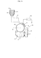
- This plastic sorting apparatus is composed of a hopper 100 into which plastic pieces a and b including two or more types mixed together are loaded, a tribo-electrifying device 101 arranged below the hopper 100 to stir the plastic pieces a and b of different types to contact them with each other, thereby electrifying the plastic pieces a and b to the respective polarities and electrification amounts according to their type, and an electrostatic separating device 105 that separates the plastic pieces a and b from each other by applying a high voltage from a high-voltage power supply 104 to a drum electrode 102 and an opposing electrode 103 both arranged below the tribo-electrifying device 101, to form a sorting electrostatic field Ea.
- the tribo-electrifying device 101 frictionally contacts the plastic pieces a and b of different types with each other to tribo-electrify them to the respective polarities and electrification amounts corresponding to an electrification array. Then, when the plastic pieces a and b are fed onto the drum electrode 102, image force is applied to the plastic pieces a and b, which are then attracted to a surface of the drum electrode 102 and carried to the sorting electrostatic field Ea.
- the forces acting on the plastic pieces a having a polarity opposite to that (-) of the drum electrode 102 are such that (image force + electrostatic force) > centrifugal force, so that the plastic pieces a remain attracted to the drum electrode 102 or fall so as to follow falling trajectories approaching the drum electrode 102 and are then collected in a separation container 107.
- Methacryl resin [acrylic resin] (hereinafter referred to as "PMMA”), polyethylene resin (hereinafter referred to as “PE”), polypropylene resin (hereinafter referred to as “PP”), and vinyl chloride resin (hereinafter referred to as “PVC”) occupy about 80% of all the plastics consumed as material for plastic products.
- PMMA polyethylene resin
- PP polypropylene resin
- PVC vinyl chloride resin
- PET polyethylene terephthalate resin used for PET bottles is separately sorted out and recovered. To use these resins as recycle material for material recycling, they must be precisely (99% or more) sorted out according to their type.
- a separator 108 arranged at the boundary between the separation containers 106 and 107 may pivot in directions A and B to adjust a separation position so as to improve the purity.
- FIG. 10 shows the relationship between the recovery rate and purity obtained by the inventors through sorting experiments in which the angle of the separator 108 was adjusted.
- Purity (%) weight (g) of plastic pieces of a predetermined type collected in a predetermined separation container/weight of all plastic pieces collected in the separation container
- FIG. 10 indicates that it is likely that an increase in purity reduces the recovery rate, whereas an increase in recovery rate reduces the purity.
- the rate at which plastic pieces are recovered becomes insufficient to make the separating operation less efficient even if the plastic pieces have an attainable purity of 99% or higher.
- the field intensity of the sorting electrostatic field Ea decreases to reduce changes of the falling trajectories of plastic pieces a and b, thereby reducing the precision (purity and.recovery rate) with which the plastic pieces a and b are separated from each other.
- a high-voltage electrode 6 with a much higher voltage must be used to form a sorting electrostatic field Ea of an increased field intensity.
- plastic pieces PMMA, PE, PP, and PVC are trobo-electrified using the tribo-electrifying device 101, they are electrified to their respective polarities and electrification amounts in accordance with the electrification array of (+ side) PMMA-PE-PP-PVC (- side).
- the PE and PP which are closely ordered in the electrification array, are contacted with each other for tribo-electrification, the PE is electrified to (+), while the PP is electrified to (-), with a small difference in electrification amount therebetween.
- the present invention provides a plastic sorting apparatus comprising a tribo-electrifying section that causes plural types of plastic pieces to frictionally contact with one another for electrification, and an upper-stage electrostatic separating section, a lower-stage electrostatic separating section and a recovery section which are all located below the tribo-electrifying section downwardly in this order, characterized in that the upper-and lower-stage electrostatic separating sections each comprises a metallic rotationally-movable electrode having a top portion to which plastic pieces are fed, an opposing electrode located to oppose a downwardly-moving portion of the rotationally movable electrode, and a high-voltage power supply for applying a high voltage to the rotationally movable electrode and opposing electrode to form a separating electrostatic field therebetween, in that a connection section is provided for feeding the rotationally movable electrode of the lower-stage electrostatic separating section with plastic pieces separated toward the rotationally movable electrode in the upper-stage electrostatic separating section, and in that polarities applied by the high
- the upper- and lower-stage electrostatic separating sections arranged in the vertical direction to electrostatically separate and sort out electrified plastic pieces according to their polarity and electrification amount, are located below the tribo-electrifying device which stirs and tribo-electrifies the plastic pieces, so that plastic pieces attracted to the rotationally movable electrode in the upper-stage electrostatic separating section or following falling trajectories approaching the rotationally movable electrode, are fed to the second electrostatic separating section via the connection section.
- Most of these plastic pieces are of a target type and have charges of a polarity opposite to that of the rotationally movable electrode of the first electrostatic separating section.
- the plastic pieces of the target type are caused to repel the rotationally movable electrode and recovered, while a small amount of plastic pieces of different types are caused to be attracted to the rotationally movable electrode or to follow the falling trajectories approaching the rotationally movable electrode for separation. Consequently, the plastic pieces of the target type can be sorted out at a high purity and a high recovery rate.
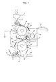
- FIGS. 1 and 2 First, a first embodiment of a plastic sorting apparatus according to the present invention will be described with reference to FIGS. 1 and 2.
- This plastic sorting apparatus comprises a tribo-electrifying device 1 that stirs at least two different types (materials) of plastic pieces (for example, plastic crushed waste to be sorted out) a and b mixed together to frictionally contact the different types of plastic pieces a and b with each other in order to tribo-electrify the plastic pieces to respective polarities and electrification amounts in accordance with their order in an electrification array, an upper-stage electrostatic separating section 10 arranged below an exit 1a of the tribo-electrifying device 1 to electrostatically separate the plural types of plastic pieces a and b from each other, and a lower-stage electrostatic separating section 30 arranged below the upper-stage electrostatic separating section 10 to further electrostatically separate one of the plural types of plastic pieces a and b separated by the upper-stage electrostatic separating section 10.
- An upper-stage connection section (connection section) 20 is provided between the upper-stage electrostatic separating section 10 and the lower-stage electrostatic separating section 30 to
- the upper-stage electrostatic separating section 10 comprises a metallic cylindrical upper-stage drum electrode 11 (rotationally movable electrode) arranged below the tribo-electrifying device 1 and rotationally driven at a predetermined velocity (peripheral velocity) in the direction of an arrow in the figure (clockwise) around a horizontal shaft, a supply chute 12 of, for example, a vibrating type which feeds an upper end of the upper-stage drum electrode 11 with a fixed amount of the plastic pieces a and b supplied by the tribo-electrifying device 1, an upper-stage opposing electrode 13 arranged obliquely above a portion of the upper-stage drum electrode 11 which rotationally moves downward, so as to form a space of a predetermined size between the drum electrode and the opposing electrode, and an upper-stage scraper 14 slidably contacting with the portion of the upper-stage drum electrode 11 which rotationally moves downward, to scrape off the plastic pieces a and b therefrom.
- a supply chute 12 of, for example,
- a positive electrode (+) of the high-voltage power supply 2 is connected to the upper-stage opposing electrode 13, while a negative electrode (-) thereof is connected to the upper-stage drum electrode 11 via an earth by a feeding brush 2a. Consequently, an upper-stage separating electrostatic field Ea1 is formed between the upper-stage drum electrode 11 and the upper-stage opposing electrode 13.
- the upper-stage connection section 20 has an upper-stage loading chute 21 and an upper-stage recovery conveyor 22 arranged therein, the upper-stage loading chute 21 collecting plastic pieces a (including a small number of plastic pieces b) electrified to a (+) polarity and separated from the other plastic pieces toward the upper-stage drum electrode 11, the upper-stage recovery conveyor 22 collecting plastic pieces b (including a small number of plastic pieces a) electrified to a (-) polarity and separated from the other plastic pieces toward the upper-stage opposing electrode 13.
- An upper-stage separator (separator) 23 is arranged between the upper-stage loading chute 21 and the upper-stage recovery conveyor 22, and comprises a separation plate arranged immediately below a peripheral side end of the upper-stage drum electrode 11 and the lower end of which is caused to pivot around an axis parallel with the axis of the upper-stage drum electrode 11 so as to adjust the separation conditions for plastic pieces a separated toward the upper-stage loading chute 21 and plastic pieces b separated toward the upper-stage recovery conveyor 22.
- the separation plate of the upper-stage separator 23 is caused to pivot by a manual rotationally-movable mechanism or actuator (not shown) so as to separate the plastic pieces a and b from each other with a desired purity.
- the lower-stage electrostatic separating section 30 comprises a metallic cylindrical lower-stage drum electrode 31 (rotationally movable electrode) arranged below an exit of the first guide chute 21 and rotationally driven at a predetermined velocity (peripheral velocity) in the direction of an arrow in the figure (counterclockwise) around a horizontal shaft parallel with the upper-stage drum electrode 11, a lower-stage opposing electrode 32 arranged obliquely above a portion of the lower-stage drum electrode 31 which rotationally moves downward, so as to form a space of a predetermined size between the drum electrode and the opposing electrode, and a lower-stage scraper 33 slidably contacting with the portion of the lower-stage drum electrode 31 which rotationally moves downward, to scrape off the attracted plastic pieces therefrom.
- a predetermined velocity peripheral velocity
- a lower-stage opposing electrode 32 arranged obliquely above a portion of the lower-stage drum electrode 31 which rotationally moves downward, so as to form a space of a predetermined size between the drum electrode and the opposing
- the positive electrode (+) of the high-voltage power supply 2 is connected to the lower-stage drum electrode 32 via a feeding brush 2b, while the negative electrode (-) thereof is connected to the lower-stage opposing electrode 32 via an earth. Consequently, a lower-stage sorting electrostatic field Ea2 is formed between the lower-stage drum electrode 31 and the lower-stage opposing electrode 32.
- the recovery section 40 has a lower-stage recovery conveyor 41 and a separation and take-out conveyor 42 both arranged below the lower-stage separating electrostatic field Ea2, the lower-stage recovery conveyor 41 collecting the plastic pieces b electrified to the (-) polarity and attracted to the second drum electrode 11 or following falling trajectories approaching the upper-stage drum electrode 11, and a separation and take-out conveyor 42 that collects, with a high purity, a large number of plastic pieces a electrified to the (+) polarity and falling from the lower-stage drum electrode 31 toward the lower-stage opposing electrode 32 owing to electrostatic force and centrifugal force.
- a second separator 43 is arranged between the lower-stage recovery conveyor 41 and the separation and take-out conveyor 42 to adjust the separation conditions for plastic pieces b separated toward the lower-stage recovery conveyor 41, located closer to the lower-stage drum electrode 31, and plastic pieces a and b separated toward the separation and take-out conveyor 42, located closer to the lower-stage opposing electrode 32.
- the second separator 43 has a separation plate arranged immediately below a peripheral side end of the lower-stage drum electrode 31 and the lower end of which is supported so as to be pivotable around an axis parallel with the axis of the lower-stage drum electrode 31.
- the separation plate is caused to pivot in the direction of an arrow in the figure by a manual rotationally-movable mechanism or actuator (not shown) so as to separate the plastic pieces a and b from each other with a desired purity.
- the upper-stages drum electrode 11 and the lower-stage drum electrode 31 are set to, for example, have the same width, outside diameter, and rotation speed so as to have an equal attraction area per unit time and thus equal processing capability in the upper-stage electrostatic separating section 10 and the lower-stage electrostatic separating section 30.
- the plastic pieces a and b are PE and PVC, respectively, and are contacted with each other by the tribo-electrifying device 1, then the PE plastic pieces a are tribo-electrified to the (+) polarity with a predetermined electrification amount, while the PVC plastic pieces b are tribo-electrified to the (-) polarity with a predetermined electrification amount.
- the plastic pieces a and b are dropped from the supply chute 12 and fed onto the upper-stage drum electrode 11 of the upper-stage electrostatic separating section 10, to which the (-) polarity has been applied, then the plastic pieces a and b are attracted, by image force, to a surface of the upper-stage drum electrode 11 and moved to the upper-stage sorting electrostatic field Ea1.
- the plastic pieces a and b are subjected to electrostatic force and centrifugal force, and the plastic pieces a (PE), which are electrified to (+), remain attracted to the upper-stage drum electrode 11 or are separated and dropped onto the upper-stage loading chute 21 by following tracks approaching the upper-stage drum electrode 11.
- plastic pieces b (PVC) electrified to (-) are repelled by the upper-stage drum electrode 11, fall following tracks approaching the upper-stage opposing electrode 13 and are then separated and collected by the intermediate recovery conveyor 22.
- the plastic pieces b (including a small number of plastic pieces a), which are collected by the intermediate recovery conveyor 22, are returned to the tribo-electrifying device 1 by a circulating device (not shown).
- the plastic pieces a and b (including a small amount of plastic pieces b) collected in the upper-stage loading chute 21 are further fed onto the lower-stage drum electrode 31 of the lower-stage electrostatic separating section 30, to which the (+) polarity has been applied. Then, the plastic pieces a and b are attracted, by image force, to a surface of the lower-stage drum electrode 31 and moved to the lower-stage separating electrostatic field Ea2. In the lower-stage separating electrostatic field Ea2, a small number of plastic pieces b electrified to (-) remain attracted to the lower-stage drum electrode 31, having the (+) polarity, or most of them fall following tracks approaching the lower-stage drum electrode 31 and are collected on the lower-stage recovery conveyor 41.
- a large amount of plastic pieces a electrified to (+) are subjected to electrostatic force and centrifugal force and are repelled by the lower-stage drum electrode 31.
- the large amount of plastic pieces a fall following tracks approaching the lower-stage opposing electrode 32 and are collected on the separation and take-out conveyor 42 with a high purity and a high recovery rate.
- the two types of plastic pieces are sorted out, but a plurality of types may be used.
- the plastic pieces b separated and collected on the lower-stage recovery conveyor 41 solely have a high purity, they may be used as sorted plastic pieces as they are.
- the lower-stage circulating device (not shown) returns the plastic pieces to the tribo-electrifying device 1.
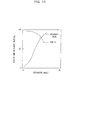
- the inventors have experimentally confirmed that with the plastic sorting apparatus shown in FIG. 9 and comprising an endless belt-like electrode, described later, as well as a drum electrode and an opposing electrode, the relationship between the mixture ratio of different types of loaded plastic pieces and the purity of plastic pieces separated toward the opposing electrode is as shown in the graph of FIG. 2.
- This figure indicates that the purity of plastic pieces of the type sorted out, separated, and carried toward the opposing electrode increases linearly with the mixture ratio of these plastic pieces to the total amount of plastic pieces loaded into the plastic sorting apparatus.
- this object can be attained by setting the electrification polarity of the separated plastic pieces to be the same as that of the high voltage applied to the drum electrode and further setting the amount of a different type of plastic pieces provided to be smaller than that of the target type of plastic pieces to set a lower mixture ratio for the former type.
- most of the plastic pieces a and b fed to the lower-stage electrostatic separating section 30 from the intermediate loading chute 21 of the upper-stage connection section 20 are the plastic pieces a, which are electrified to the (+) polarity, because the amount of the plastic pieces b, electrified to the (-) polarity and separated by the upper-stage electrostatic separating section 10, is substantially reduced. Then, a high voltage of the (+) polarity is applied to the lower-stage drum electrode 31 of the lower-stage electrostatic separating section 30 to reliably remove the small amount of plastic pieces b, thereby allowing the plastic pieces a to be collected on the separation and take-out conveyor 42 with a high purity and a high recovery rate.
- plastic pieces PE which are electrified to (+), and plastic pieces PVC, which are electrified to (-), were supplied to the tribo-electrifying device 1 after being mixed together so that the mixture ratio of 50% of the former to the latter was 1:1
- the plastic pieces PE could be collected on the separation and take-out conveyor 42 of the recovery section 40 with a high purity exceeding 99% and a high recovery rate of 90% or more.
- the amount of plastic pieces processed was 300 Kg/H
- the drum electrodes 11 and 31 had a peripheral velocity of about 50 m/sec
- a voltage of 30 KV was applied by the high-voltage power supply 2.
- the lower-stage electrostatic separating section 30 is provided with a lower-stage upper-level electrostatic sorting section 50 and a lower-stage lower-level electrostatic sorting section 70 which are arranged in the vertical direction and connected together by a lower-stage connection section 60.
- the lower-stage upper-level electrostatic sorting section 50 comprises a lower-stage upper-level drum electrode 51 (rotationally movable electrode) arranged below an exit of the upper-stage loading chute 21 and rotationally driven in the direction of an arrow in the figure (counterclockwise), a lower-stage upper-level opposing electrode 52 arranged so as to form a space of a predetermined size between the lower-stage upper-level drum electrode 31 and the opposing electrode 52, and a lower-stage upper-level scraper 53 slidably contacting with the lower-stage upper-level drum electrode 51 to scrape off the plastic pieces therefrom.
- a lower-stage upper-level drum electrode 51 rotationally movable electrode
- a lower-stage upper-level opposing electrode 52 arranged so as to form a space of a predetermined size between the lower-stage upper-level drum electrode 31 and the opposing electrode 52
- a lower-stage upper-level scraper 53 slidably contacting with the lower-stage upper-level drum electrode 51 to scrape off the plastic pieces therefrom
- the positive electrode (+) of the high-voltage power supply 2 is connected to the lower-stage upper-level drum electrode 51, while the negative electrode (-) thereof is connected to the lower-stage upper-level opposing electrode 52 via an earth. Consequently, a lower-stage upper-level separating electrostatic field Ea3 is formed between the lower-stage upper-level drum electrode 51 and the lower-stage upper-level opposing electrode 52.
- the lower-stage connection section 60 has a lower-stage loading chute 61 and a lower-stage recovery conveyor 62 both arranged below the lower-stage upper-level separating electrostatic field Ea3, the lower-stage loading chute 61 collecting plastic pieces a (including a small number of plastic pieces b) electrified to the (+) polarity and separated toward the lower-stage upper-level opposing electrode 52, the lower-stage recovery conveyor 62 collecting plastic pieces b (including a small number of plastic pieces a) electrified to the (-) polarity and separated toward the lower-stage upper-level drum electrode 51.
- a lower-stage separator(separator) is arranged below the lower-stage upper-level separating electrostatic field Ea3 and between the lower-stage loading chute 61 and the lower-stage recovery conveyor 62, and comprises a separation plate to adjust the separation conditions for plastic pieces a separated toward the lower-stage upper-level loading chute 61 and plastic pieces b separated toward the lower-stage recovery conveyor 62.
- the lower-stage lower-level electrostatic sorting section 70 comprises a lower-stage lower-level drum electrode 71 (rotationally movable electrode) arranged below an exit of the lower-stage loading guide chute 61 and rotationally driven in the direction of an arrow in the figure (clockwise), a lower-stage lower-level opposing electrode 72 arranged so as to form a space of a predetermined size between the lower-level drum electrode 71 and the opposing electrode 72, and a lower-stage lower-level scraper 73 slidably contacting with the lower-stage lower-level drum electrode 71 to scrape off the plastic pieces therefrom.
- a lower-stage lower-level drum electrode 71 rotationally movable electrode
- a lower-stage lower-level opposing electrode 72 arranged so as to form a space of a predetermined size between the lower-level drum electrode 71 and the opposing electrode 72
- a lower-stage lower-level scraper 73 slidably contacting with the lower-stage lower-level drum electrode 71 to scrape off the plastic
- the positive electrode (+) of the high-voltage power supply 2 is connected to the lower-stage lower-level drum electrode 71, while the negative electrode (-) thereof is connected to the lower-stage lower-level opposing electrode 72 via an earth. Consequently, a lower-stage lower-level separating electrostatic field Ea4 is formed between the lower-stage lower-level drum electrode 71 and the lower-stage lower-level opposing electrode 72.
- plastic pieces a and b separated toward the lower-stage upper-level opposing electrode 52 in the lower-stage upper-level electrostatic sorting section 50 are fed to the lower-stage lower-level electrostatic separating section 70 via the lower-stage loading chute 61 of the lower-stage connection section 60.
- most of the plastic pieces a and b are plastic pieces a separated by the lower-stage upper-level electrostatic separating section 50 of the upper-stage electrostatic separating section 10 and most of which have been electrified to (+).
- These plastic pieces a are mixed with plastic pieces b slightly electrified to (-).
- plastic pieces a and b are fed to the lower-level lower-stage electrostatic sorting section 70, a large amount of plastic pieces a are separated and collected on the separation and take-out conveyor 42 with a high purity and a high recovery rate, the conveyor 42 being located closer to the lower-stage lower-level opposing electrode 72. In addition, a small number of plastic pieces b are reliably separated and collected on the lower-stage recovery conveyor 41, located closer to the lower-stage lower-level drum electrode 71.
- the different types of plastic pieces can be separated from each other with a higher purity and a higher recovery rate than in the first embodiment. Furthermore, even if the different types of plastic pieces have only a small difference in electrification amount therebetween, these types can be separated from each other with a high purity and a high recovery rate.
- FIG. 4 a third embodiment of a plastic sorting apparatus will be described with reference to FIG. 4.
- the same members as those in the above embodiments are denoted by the same reference numerals, and their description is thus omitted.
- plastic pieces a including a small amount of plastic pieces b separated toward the upper-stage drum electrode 11 in the upper-stage electrostatic separating section 10 are fed to the lower-stage electrostatic separating section 30 via the upper-stage connection section 20.
- plastic pieces b including a small amount of plastic pieces a) separated toward the upper-stage opposing electrode 13 in the upper-stage electrostatic separating section 10 are fed to the lower-stage electrostatic separating section 90 via the upper-stage connection section 80.
- the upper-stage connection section 80 comprises an upper-stage loading chute 81 that receives and feeds plastic pieces a and b separated toward the upper-stage opposing electrode 13, to the lower-stage electrostatic separating section 90, an upper-stage recovery conveyor 82 that receives plastic pieces a and b separated toward the upper-stage drum electrode 11, and an upper-stage separator 83 that can use a separation plate to adjust the separation conditions for the plastic pieces.
- the plastic pieces a and b collected on the upper-stage recovery conveyor 82 are returned to the tribo-electrifying device 1 by the circulating device (not shown) as required.
- the lower-stage electrostatic separating section 90 comprises a lower-stage drum electrode 91, a lower-stage opposing electrode 92, and a lower-stage scraper 93 as in the case with the first embodiment, but differs therefrom in that the positive electrode (+) of the high-voltage power supply 2 is connected to the lower-stage opposing electrode 92, while the negative electrode (-) thereof is connected to the lower-stage drum electrode 91 via an earth.
- a lower-stage separating electrostatic field Ea5 is formed between the lower-stage drum electrode 91 and the lower-stage opposing electrode 92.
- plastic pieces b (including a small amount of plastic pieces a) separated toward the upper-stage opposing electrode 13 in the upper-stage electrostatic separating section 10 are fed to the lower-stage drum electrode 91 of the lower-stage electrostatic separating section 90 via the upper-stage loading chute 81 of the upper-stage connection section 80.
- a large amount of plastic pieces b, which have been: electrified to (-) are separated toward the lower-stage opposing electrode 92 and received by the separation and take-out conveyor 42, whereas a small amount of plastic pieces a, which have been electrified to (+), are separated toward the lower-stage drum electrode 91 and received by the lower-stage recovery conveyor 41.
- the graph of FIG. 2 indicates that if of the plastic pieces a and b loaded from the tribo-electrifying device 1, the target plastic pieces b have a higher mixture ratio than the plastic pieces a, then the plastic pieces b can be separated and collected on the separation and take-out conveyor 42 with a higher purity and a higher recovery rate.
- FIG. 5 a fourth embodiment of a plastic sorting apparatus will be described with reference to FIG. 5.
- the same members as those in the above embodiments are denoted by the same reference numerals, and their description is thus omitted.
- the lower-stage electrostatic sorting section 90 of the third embodiment is constructed similarly to the second embodiment, and high voltages of the same polarities as those in the upper-stage electrostatic sorting section 10 are applied to the lower-stage upper-level electrostatic sorting section 50 and lower-stage lower-level electrostatic sorting section 70 by the high-voltage power supply 2.
- plastic pieces b separated toward the upper-stage opposing electrode 13 in the upper-stage electrostatic separating section 10 can further be separated and collected on the separation and take-out conveyor 42 with a high purity and a high recovery rate. Even if the different types of plastic pieces have only a small difference in electrification amount therebetween, these types can be separated from each other with a high purity and a high recovery rate. Further, the graph of FIG. 2 indicates that if of the plastic pieces loaded from the tribo-electrifying device 1, the target plastic pieces b have a higher mixture ratio than the plastic pieces a, then the plastic pieces, b can be separated from the plastic pieces a with a higher purity and a higher recovery rate.
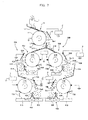
- FIG. 6 shows a fifth embodiment of a plastic sorting apparatus.
- This plastic sorting apparatus is obtained by merging the first and third embodiments together, and comprises the single upper-stage electrostatic separating section 10 used for the purposes of both embodiments, and a lower-stage first and second electrostatic sorting sections 30A and 30B and a first and second recovery sections 40A and 40B all of which are arranged below the upper-stage electrostatic sorting section 10 via an upper-stage connection section 25.
- the upper-stage connection section 25 is provided with an upper-stage first loading chute 26 that receives and feeds plastic pieces a (including a small amount of plastic pieces b) separated toward the upper-stage drum electrode 11, to the lower-stage first electrostatic sorting section 30A, an upper-stage second loading chute 27 that receives and feeds plastic pieces b (including a small amount of plastic pieces a) separated toward the upper-stage opposing electrode 13, to the lower-stage second electrostatic sorting section 30B, and an upper-stage separator 28.
- an upper-stage first loading chute 26 that receives and feeds plastic pieces a (including a small amount of plastic pieces b) separated toward the upper-stage drum electrode 11, to the lower-stage first electrostatic sorting section 30A
- an upper-stage second loading chute 27 that receives and feeds plastic pieces b (including a small amount of plastic pieces a) separated toward the upper-stage opposing electrode 13, to the lower-stage second electrostatic sorting section 30B
- an upper-stage separator 28 an upper-stage separator 28.
- the lower-stage first electrostatic sorting section 30A comprises a lower-stage first drum electrode (rotationally movable electrode) 31A arranged below an exit of an upper-stage first loading chute 21A and rotationally driven in the direction of an arrow in the figure (counterclockwise), a lower-stage first opposing electrode 32A arranged so as to form a space of a predetermined size between the lower-stage first drum electrode 31A and the opposing electrode 32A, and a lower-stage first scraper 33A that scrapes off the plastic pieces b from the lower-stage first drum electrode 31A.
- a lower-stage first drum electrode rotationally movable electrode
- the positive electrode (+) of the high-voltage power supply 2 is connected to the lower-stage first drum electrode 31A, while the negative electrode (-) thereof is connected to the lower-stage first opposing electrode 32A via an earth. Consequently, a lower-stage first separating electrostatic field Ea6 is formed between the lower-stage first drum electrode 31A and the lower-stage first opposing electrode 32A.
- the first recovery section (recovery section) 40A has a lower-stage first recovery conveyor 41A and a lower-stage first separation and take-out conveyor 42A, the lower-stage first recovery conveyor 41A receiving plastic pieces b separated toward the lower-stage first drum electrode 31A, the lower-stage first separation and take-out conveyor 42A receiving plastic pieces a separated toward the lower-stage first opposing electrode 32A.
- the plastic pieces b on the lower-stage first recovery conveyor 41A are returned.to the tribo-electrifying device 1 by the circulating device (not shown) as required.
- the lower-stage second electrostatic sorting section 30B comprises a lower-stage second drum electrode (rotationally movable electrode) 31B arranged below an exit of the second loading chute 21B and rotationally driven in the direction of an arrow in the figure (counterclockwise), a lower-stage second opposing electrode 32B arranged so as to form a space of a predetermined size between the lower-stage second drum electrode 31B and the opposing electrode 32B, and a lower-stage second scraper 33B slidably contacting with the lower-stage second drum electrode 31B to scrape off the attracted plastic pieces a therefrom.
- a lower-stage second drum electrode rotationally movable electrode
- the positive electrode (+) of the high-voltage power supply 2 is connected to the lower-stage second opposing electrode 32B, while the negative electrode (-) thereof is connected to the lower-stage second drum electrode 31B via an earth. Consequently, a lower-stage second separating electrostatic field Ea7 is formed between the lower-stage second drum electrode 31B and the lower-stage second opposing electrode 32B.
- the second recovery section (recovery section) 40B has a lower-stage second recovery conveyor 41B and a lower-stage second separation and take-out conveyor 42B, the lower-stage second recovery conveyor 41B receiving plastic pieces a separated toward the lower-stage second drum electrode 31B, the lower-stage second separation and take-out conveyor 42B receiving plastic pieces b separated toward the lower-stage second opposing electrode 32B.
- the plastic pieces a on the lower-stage second recovery conveyor 41B are returned to the tribo-electrifying device 1 by the circulating device (not shown) as required.
- the plastic pieces a and b separated by the upper-stage electrostatic separating section 10 are fed to the lower-stage first electrostatic sorting section 30A and to the lower-stage second electrostatic sorting section 30B for separation.
- the plastic pieces a and b supplied by the upper-stage first loading chute 21A a small amount of plastic pieces b are separated toward the lower-stage first drum electrode 31A in the lower-stage first electrostatic sorting section 30A, while a large amount of plastic pieces a are separated toward the lower-stage first opposing electrode 32B. Consequently, the plastic pieces a to be collected on the lower-stage first separation and take-out conveyor 42A can be separated from the other plastic pieces with a high purity and a high recovery rate.
- plastic pieces a and b supplied by the upper-stage second loading chute 21B a small amount of plastic pieces a are separated toward the lower-stage second drum electrode 31B in the lower-stage second electrostatic sorting section 30B, while a large amount of plastic pieces b are separated toward the lower-stage second opposing electrode 32B. Consequently, the plastic pieces b to be collected on the lower-stage second separation and take-out conveyor 42B can be separated from the other plastic pieces with a high purity and a high recovery rate.
- plastic pieces a having the largest electrification amount on the (+) side and plastic pieces b having the largest electrification amount on the (-) side can be simultaneously separated from the other plastic pieces with a high purity and a high recovery rate.
- FIG. 7 shows a sixth embodiment of a plastic sorting apparatus.
- This plastic sorting apparatus is obtained by merging the second and fourth embodiments together, wherein the lower-stage first electrostatic separating section 30A is composed of a lower-stage first upper-level electrostatic sorting section 50A, a lower-stage first connection section 60A, and a lower-stage first lower-level electrostatic sorting section 70A, and the lower-stage second electrostatic sorting section 30B is composed of a lower-stage second upper-level electrostatic sorting section 50B, a lower-stage second connection section 60B, and a lower-stage second lower-level electrostatic sorting section 70B.
- the lower-stage first electrostatic separating section 30A is composed of a lower-stage first upper-level electrostatic sorting section 50A, a lower-stage first connection section 60A, and a lower-stage first lower-level electrostatic sorting section 70A
- the lower-stage second electrostatic sorting section 30B is composed of a lower-stage second upper-level electrostatic sorting section 50B, a lower-stage second connection section 60B, and a lower
- the lower-stage first upper-level electrostatic sorting section 50A comprises a lower-stage first upper-level drum electrode 51A (rotationally movable electrode) arranged below an exit of the upper-stage first loading chute 21A, a lower-stage first upper-level opposing electrode 52A, and a lower-stage first upper-level scraper 53A.
- the positive electrode (+) of the high-voltage power supply 2 is connected to the lower-stage first upper-level drum electrode 51A, while the negative electrode (-) thereof is connected to the lower-stage first upper-level opposing electrode 52A via an earth. Consequently, a lower-stage first upper-level sorting electrostatic field Ea8 is formed between the lower-stage first upper-level drum electrode 51A and the lower-stage first upper-level opposing electrode 52A.
- the lower-stage first connection section 60A has a lower-stage first loading chute 61A and a lower-stage first recovery conveyor 62A both arranged below the lower-stage first upper-level sorting electrostatic field Ea8, the lower-stage first loading chute 61A collecting plastic pieces a (including a small number of plastic pieces b) separated toward the lower-stage upper-level drum electrode 11, the lower-stage first recovery conveyor 62A collecting plastic pieces b (including a small number of plastic pieces a) separated toward the upper-stage opposing electrode 13.
- a lower-stage first separator (separator) 63A is provided which causes a separation plate to pivot so as to adjust the separation conditions for plastic pieces b separated toward the lower-stage first upper-level drum electrode 51A and plastic pieces a separated toward the lower-stage first upper-level opposing electrode 52A.
- the lower-stage first lower-level electrostatic sorting section 70A comprises a lower-stage first lower-level drum electrode (rotationally movable electrode) 71A arranged below an exit of the lower-stage first loading guide chute 61A, a lower-stage first lower-level opposing electrode 72A, and a lower-stage first lower-level scraper 73A.
- the positive electrode (+) of the high-voltage power supply 2 is connected to the lower-stage first lower-level drum electrode 71A, while the negative electrode (-) thereof is connected to the lower-stage first lower-level opposing electrode 72A via an earth. Consequently, a lower-stage first lower-level sorting electrostatic field Ea9 is formed between the lower-stage first lower-level drum electrode 71A and the lower-stage first lower-level opposing electrode 72A.
- the first recovery section 40A located below the lower-stage first lower-level sorting electrostatic field Ea9, is provided with a lower-stage first recovery conveyor 41A that receives plastic pieces b separated toward the lower-stage first lower-level drum electrode 71A, a first separation and take-out conveyor 42A that receives plastic pieces a separated toward the lower-stage first lower-level opposing electrode 72A, and a lower-stage first separator 43A that can adjust the above described separation conditions.
- the lower-stage second upper-level electrostatic sorting section 50B comprises a lower-stage second upper-level drum electrode 51B (rotationally movable electrode) arranged below an exit of the second upper-stage loading chute 21B, a lower-stage second upper-level opposing electrode 52B, and a lower-stage second upper-level scraper 53B.
- the positive electrode (+) of the high-voltage power supply 2 is connected to the lower-stage second upper-level opposing electrode 52B, while the negative electrode (-) thereof is connected to the lower-stage second upper-level drum electrode 51B via an earth. Consequently, a lower-stage upper-level separating electrostatic field Ea10 is formed between the lower-stage-second upper-level drum electrode 51B and the lower-stage second upper-level opposing electrode 52B.
- the second lower-stage connection section 60B has a lower-stage second loading chute 61B and a lower-stage second recovery conveyor 62B both arranged therein, the lower-stage second loading chute 61B collecting plastic pieces a (including a small number of plastic pieces b) separated toward the lower-stage second upper-level drum electrode 51B, the lower-stage second recovery conveyor 62B collecting plastic pieces b (including a small number of plastic pieces a) separated toward the upper-stage second upper-level opposing electrode 53B.
- a lower-stage second separator (separator) 63B is provided which causes a separation plate to pivot so as to adjust the separation conditions for plastic pieces b separated toward-the lower-stage second upper-level drum electrode 51B and plastic pieces b separated toward the lower-stage second upper-level opposing electrode 52B.
- the lower-stage second lower-level electrostatic sorting section 70B comprises a lower-stage second lower-level drum electrode (rotationally movable electrode) 71B arranged below an exit of the lower-stage second loading guide chute 61B, a lower-stage second lower-level opposing electrode 72B, and a lower-stage second lower-level scraper 73B.
- the positive electrode (+) of the high-voltage power supply 2 is connected to the lower-stage second lower-level opposing electrode 72B, while the negative electrode (-) thereof is connected to the lower-stage second lower-level drum electrode 71B via an earth. Consequently, a lower-stage second lower-level sorting electrostatic field Ea11 is formed between the lower-stage second lower-level drum electrode 71B and the lower-stage second lower-level opposing electrode 72B.
- the second recovery section 40B located below the lower-stage second lower-level sorting electrostatic field Ea11, is provided with a lower-stage second recovery conveyor 41B that receives plastic pieces a separated toward the lower-stage second lower-level drum electrode 71B, a second separation and take-out conveyor 42B that receives plastic pieces a separated toward the lower-stage second lower-level opposing electrode 72B, and a lower-stage second separator 43B that can adjust the above described separation conditions.
- the second and fourth embodiments are combined together, so that the plastic pieces a, which are electrified to (+), and the plastic pieces b, which are electrified to (-), can be simultaneously collected on the first and second separation and take-out conveyors 42A and 42B, respectively, with a higher purity and a higher recovery rate. Even if the different types of plastic pieces have only a small difference in electrification amount therebetween, these types can be separated from each other with a high purity and a high recovery rate.
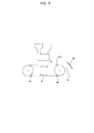
- the rotationally movable electrode is a drum electrode but may be composed of a metallic belt-like endless belt electrode 97 wound around and extended between rotating members 95 and 96 arranged horizontally opposite each other and parallel with each other as shown in FIG. 8.
- the plastic pieces can be stably attracted to a surface of the belt electrode 97 using image force and can then be fed into a separating electrostatic field Ea formed between the belt electrode 97 and an opposing electrode 98 arranged obliquely above a portion of the belt electrode 97 which rotationally moves downward.
- the separation precision can further be improved.
- the lower-stage electrostatic sorting section comprises an upper- and lower-level electrostatic sorting sections.
- the apparatus may have three or more electrostatic sorting sections arranged therein.
- the plastic sorting apparatus is suitable for separating plastic crushed pieces to be collected and recycled, from one another according to their type with a high purity and a high recovery rate.
Landscapes
- Engineering & Computer Science (AREA)
- Environmental & Geological Engineering (AREA)
- Mechanical Engineering (AREA)
- Electrostatic Separation (AREA)
- Separation, Recovery Or Treatment Of Waste Materials Containing Plastics (AREA)
Abstract
A first and second electrostatic sorting sections are
arranged below a tribo-electrifying device in this order in
a vertical direction to form a sorting electrostatic field
between a drum electrode and an opposing electrode. Plastic
pieces separated from the other plastic pieces by the sorting
electrostatic field in the first electrostatic separating
section are introduced into a sorting electrostatic field in
the second electrostatic separating section for second
separation, thereby increasing the separation purity and
recovery rate of plastic pieces.
Description
The present invention relates to a plastic sorting
apparatus for sorting crushed plastic pieces composed of
plural types of plastics, according to their types.
A conventional plastic sorting apparatus comprises two
electrode plates arranged parallel with each other in a
vertical direction so as to form a space of a predetermined
size therebetween, the electrode plates having a high-voltage
power supply connected thereto to form a separating
electrostatic field therebetween, wherein plastic pieces are
loaded into the separating electrostatic field from above,
and the electrostatic force of the separating electrostatic
field is used to vary the falling trajectories of the plastic
pieces correspondingly to the charges of the plastic pieces,
thereby separating the plastic pieces from one another
according to their type.
However, to improve the separation precision of the .
conventional apparatuses, it is necessary to use long
electrode plates to increase the time required for the plastic
pieces to pass through the separating electrostatic field,
which disadvantageously requires the size of the apparatuses
to be increased. Further, the plastic pieces may adhere to
the electrodes, resulting in degraded separation performance,
to hinder continuous processing.
Thus, the inventors have proposed the plastic sorting
apparatus shown in Fig. 9 as a technique for sorting out
crushed plastic pieces. This plastic sorting apparatus is
composed of a hopper 100 into which plastic pieces a and b
including two or more types mixed together are loaded, a
tribo-electrifying device 101 arranged below the hopper 100
to stir the plastic pieces a and b of different types to contact
them with each other, thereby electrifying the plastic pieces
a and b to the respective polarities and electrification
amounts according to their type, and an electrostatic
separating device 105 that separates the plastic pieces a and
b from each other by applying a high voltage from a high-voltage
power supply 104 to a drum electrode 102 and an
opposing electrode 103 both arranged below the tribo-electrifying
device 101, to form a sorting electrostatic
field Ea.
In this plastic sorting apparatus, the tribo-electrifying
device 101 frictionally contacts the plastic
pieces a and b of different types with each other to
tribo-electrify them to the respective polarities and
electrification amounts corresponding to an electrification
array. Then, when the plastic pieces a and b are fed onto
the drum electrode 102, image force is applied to the plastic
pieces a and b, which are then attracted to a surface of the
drum electrode 102 and carried to the sorting electrostatic
field Ea. Then, in the sorting electrostatic field Ea,
electrostatic force and centrifugal force are applied to the
plastic pieces a and b, so that the forces acting on the plastic
pieces b having the same polarity (-) as that of the drum
electrode 102 are such that image force < (electrostatic force
+ centrifugal force). As a result, the plastic pieces b fall
so as to follow falling trajectories extending from a surface
of the metal drum electrode 102 to the opposing electrode 103
and are thus collected in a separation container 106. On the
contrary, the forces acting on the plastic pieces a having
a polarity opposite to that (-) of the drum electrode 102 are
such that (image force + electrostatic force) > centrifugal
force, so that the plastic pieces a remain attracted to the
drum electrode 102 or fall so as to follow falling
trajectories approaching the drum electrode 102 and are then
collected in a separation container 107.
Methacryl resin [acrylic resin] (hereinafter referred
to as "PMMA"), polyethylene resin (hereinafter referred to
as "PE"), polypropylene resin (hereinafter referred to as
"PP"), and vinyl chloride resin (hereinafter referred to as
"PVC") occupy about 80% of all the plastics consumed as
material for plastic products. Further, polyethylene
terephthalate resin (hereinafter referred to as "PET") used
for PET bottles is separately sorted out and recovered. To
use these resins as recycle material for material recycling,
they must be precisely (99% or more) sorted out according to
their type.
Further, it is contemplated that in order to achieve a
high purity and a high recovery rate with the electrostatic
separating device 105 of the above described plastic sorting
apparatus, a separator 108 arranged at the boundary between
the separation containers 106 and 107 may pivot in directions
A and B to adjust a separation position so as to improve the
purity.
FIG. 10 shows the relationship between the recovery rate
and purity obtained by the inventors through sorting
experiments in which the angle of the separator 108 was
adjusted. In this figure, the purity and the recovery rate
are determined using the following equation:
Recovery rate (%) = weight (g) of plastic pieces of a
target type collected in a predetermined separation
container/total weight of plastic pieces of the target type
loaded into an electrostatic separating device
Purity (%) = weight (g) of plastic pieces of a
predetermined type collected in a predetermined separation
container/weight of all plastic pieces collected in the
separation container
FIG. 10 indicates that it is likely that an increase in
purity reduces the recovery rate, whereas an increase in
recovery rate reduces the purity. Thus, if plastic pieces
are to be recovered according to their material, the rate at
which plastic pieces are recovered becomes insufficient to
make the separating operation less efficient even if the
plastic pieces have an attainable purity of 99% or higher.
Further, with a lower voltage applied to the drum
electrode 102 and opposing electrode 103, the field intensity
of the sorting electrostatic field Ea decreases to reduce
changes of the falling trajectories of plastic pieces a and
b, thereby reducing the precision (purity and.recovery rate)
with which the plastic pieces a and b are separated from each
other. Thus, to increase the separation precision for the
plastic pieces a and b, a high-voltage electrode 6 with a much
higher voltage must be used to form a sorting electrostatic
field Ea of an increased field intensity. In this case,
however, a very high voltage must be applied to the metal drum
electrode 102 and opposing electrode 103, and all members of
the electrostatic separating device 105 must thus have
high-voltage-resistant and highly-insulated structures,
thereby substantially increasing facility costs.
consequently, it is difficult to apply a voltage exceeding a predetermined value.
consequently, it is difficult to apply a voltage exceeding a predetermined value.
Furthermore, when plastic pieces PMMA, PE, PP, and PVC
are trobo-electrified using the tribo-electrifying device
101, they are electrified to their respective polarities and
electrification amounts in accordance with the
electrification array of (+ side) PMMA-PE-PP-PVC (- side).
For example, if PE and PP, which are closely ordered in the
electrification array, are contacted with each other for
tribo-electrification, the PE is electrified to (+), while
the PP is electrified to (-), with a small difference in
electrification amount therebetween. Accordingly, if
different types of plastic pieces are mixed together which
are closely ordered in the electrification array and have only
a small difference in electrification amount therebetween,
then a problem with the above described conventional plastic
sorting apparatus is that the plastic pieces cannot be sorted
out with a high purity of 99% or higher and a high recovery
rate.
It is an object of the present invention to provide a
plastic sorting apparatus that can sort out plastic pieces
according to their type with a high purity and a high recovery
rate.
The present invention provides a plastic sorting
apparatus comprising a tribo-electrifying section that
causes plural types of plastic pieces to frictionally contact
with one another for electrification, and an upper-stage
electrostatic separating section, a lower-stage
electrostatic separating section and a recovery section which
are all located below the tribo-electrifying section
downwardly in this order, characterized in that the upper-and
lower-stage electrostatic separating sections each
comprises a metallic rotationally-movable electrode having
a top portion to which plastic pieces are fed, an opposing
electrode located to oppose a downwardly-moving portion of
the rotationally movable electrode, and a high-voltage power
supply for applying a high voltage to the rotationally movable
electrode and opposing electrode to form a separating
electrostatic field therebetween, in that a connection
section is provided for feeding the rotationally movable
electrode of the lower-stage electrostatic separating
section with plastic pieces separated toward the rotationally
movable electrode in the upper-stage electrostatic
separating section, and in that polarities applied by the
high-voltage power supply respectively to the rotationally
movable electrode and opposing electrode in the upper-stage
electrostatic separating section are opposite to polarities
applied by the high-voltage power supply to the rotationally
movable electrode and opposing electrode in the lower-stage
electrostatic separating section.
According to this construction, the upper- and
lower-stage electrostatic separating sections, arranged in
the vertical direction to electrostatically separate and sort
out electrified plastic pieces according to their polarity
and electrification amount, are located below the tribo-electrifying
device which stirs and tribo-electrifies the
plastic pieces, so that plastic pieces attracted to the
rotationally movable electrode in the upper-stage
electrostatic separating section or following falling
trajectories approaching the rotationally movable electrode,
are fed to the second electrostatic separating section via
the connection section. Most of these plastic pieces are of
a target type and have charges of a polarity opposite to that
of the rotationally movable electrode of the first
electrostatic separating section. In the second
electrostatic separating section, the plastic pieces of the
target type are caused to repel the rotationally movable
electrode and recovered, while a small amount of plastic
pieces of different types are caused to be attracted to the
rotationally movable electrode or to follow the falling
trajectories approaching the rotationally movable electrode
for separation. Consequently, the plastic pieces of the
target type can be sorted out at a high purity and a high
recovery rate.
The present invention will be described in further detail
with reference to the attached drawings.
First, a first embodiment of a plastic sorting apparatus
according to the present invention will be described with
reference to FIGS. 1 and 2.
This plastic sorting apparatus comprises a tribo-electrifying
device 1 that stirs at least two different types
(materials) of plastic pieces (for example, plastic crushed
waste to be sorted out) a and b mixed together to frictionally
contact the different types of plastic pieces a and b with
each other in order to tribo-electrify the plastic pieces to
respective polarities and electrification amounts in
accordance with their order in an electrification array, an
upper-stage electrostatic separating section 10 arranged
below an exit 1a of the tribo-electrifying device 1 to
electrostatically separate the plural types of plastic pieces
a and b from each other, and a lower-stage electrostatic
separating section 30 arranged below the upper-stage
electrostatic separating section 10 to further
electrostatically separate one of the plural types of plastic
pieces a and b separated by the upper-stage electrostatic
separating section 10. An upper-stage connection section
(connection section) 20 is provided between the upper-stage
electrostatic separating section 10 and the lower-stage
electrostatic separating section 30 to guide the separated
plastic pieces. Further, a recovery section 40 is provided
below the lower-stage electrostatic separating section 30.
The upper-stage electrostatic separating section 10
comprises a metallic cylindrical upper-stage drum electrode
11 (rotationally movable electrode) arranged below the
tribo-electrifying device 1 and rotationally driven at a
predetermined velocity (peripheral velocity) in the
direction of an arrow in the figure (clockwise) around a
horizontal shaft, a supply chute 12 of, for example, a
vibrating type which feeds an upper end of the upper-stage
drum electrode 11 with a fixed amount of the plastic pieces
a and b supplied by the tribo-electrifying device 1, an
upper-stage opposing electrode 13 arranged obliquely above
a portion of the upper-stage drum electrode 11 which
rotationally moves downward, so as to form a space of a
predetermined size between the drum electrode and the
opposing electrode, and an upper-stage scraper 14 slidably
contacting with the portion of the upper-stage drum electrode
11 which rotationally moves downward, to scrape off the
plastic pieces a and b therefrom. Then, for example, a
positive electrode (+) of the high-voltage power supply 2 is
connected to the upper-stage opposing electrode 13, while a
negative electrode (-) thereof is connected to the upper-stage
drum electrode 11 via an earth by a feeding brush 2a.
Consequently, an upper-stage separating electrostatic field
Ea1 is formed between the upper-stage drum electrode 11 and
the upper-stage opposing electrode 13.
Further, the upper-stage connection section 20 has an
upper-stage loading chute 21 and an upper-stage recovery
conveyor 22 arranged therein, the upper-stage loading chute
21 collecting plastic pieces a (including a small number of
plastic pieces b) electrified to a (+) polarity and separated
from the other plastic pieces toward the upper-stage drum
electrode 11, the upper-stage recovery conveyor 22 collecting
plastic pieces b (including a small number of plastic pieces
a) electrified to a (-) polarity and separated from the other
plastic pieces toward the upper-stage opposing electrode 13.
An upper-stage separator (separator) 23 is arranged between
the upper-stage loading chute 21 and the upper-stage recovery
conveyor 22, and comprises a separation plate arranged
immediately below a peripheral side end of the upper-stage
drum electrode 11 and the lower end of which is caused to pivot
around an axis parallel with the axis of the upper-stage drum
electrode 11 so as to adjust the separation conditions for
plastic pieces a separated toward the upper-stage loading
chute 21 and plastic pieces b separated toward the upper-stage
recovery conveyor 22. The separation plate of the
upper-stage separator 23 is caused to pivot by a manual
rotationally-movable mechanism or actuator (not shown) so as
to separate the plastic pieces a and b from each other with
a desired purity.
The lower-stage electrostatic separating section 30
comprises a metallic cylindrical lower-stage drum electrode
31 (rotationally movable electrode) arranged below an exit
of the first guide chute 21 and rotationally driven at a
predetermined velocity (peripheral velocity) in the
direction of an arrow in the figure (counterclockwise) around
a horizontal shaft parallel with the upper-stage drum
electrode 11, a lower-stage opposing electrode 32 arranged
obliquely above a portion of the lower-stage drum electrode
31 which rotationally moves downward, so as to form a space
of a predetermined size between the drum electrode and the
opposing electrode, and a lower-stage scraper 33 slidably
contacting with the portion of the lower-stage drum electrode
31 which rotationally moves downward, to scrape off the
attracted plastic pieces therefrom. The positive electrode
(+) of the high-voltage power supply 2 is connected to the
lower-stage drum electrode 32 via a feeding brush 2b, while
the negative electrode (-) thereof is connected to the
lower-stage opposing electrode 32 via an earth.
Consequently, a lower-stage sorting electrostatic field Ea2 is formed between the lower-stage drum electrode 31 and the
lower-stage opposing electrode 32.
Consequently, a lower-stage sorting electrostatic field Ea2 is formed between the lower-
Furthermore, the recovery section 40 has a lower-stage
recovery conveyor 41 and a separation and take-out conveyor
42 both arranged below the lower-stage separating
electrostatic field Ea2, the lower-stage recovery conveyor
41 collecting the plastic pieces b electrified to the (-)
polarity and attracted to the second drum electrode 11 or
following falling trajectories approaching the upper-stage
drum electrode 11, and a separation and take-out conveyor 42
that collects, with a high purity, a large number of plastic
pieces a electrified to the (+) polarity and falling from the
lower-stage drum electrode 31 toward the lower-stage opposing
electrode 32 owing to electrostatic force and centrifugal
force. Further, a second separator 43 is arranged between
the lower-stage recovery conveyor 41 and the separation and
take-out conveyor 42 to adjust the separation conditions for
plastic pieces b separated toward the lower-stage recovery
conveyor 41, located closer to the lower-stage drum electrode
31, and plastic pieces a and b separated toward the separation
and take-out conveyor 42, located closer to the lower-stage
opposing electrode 32. The second separator 43 has a
separation plate arranged immediately below a peripheral side
end of the lower-stage drum electrode 31 and the lower end
of which is supported so as to be pivotable around an axis
parallel with the axis of the lower-stage drum electrode 31.
The separation plate is caused to pivot in the direction of
an arrow in the figure by a manual rotationally-movable
mechanism or actuator (not shown) so as to separate the
plastic pieces a and b from each other with a desired purity.
The upper-stages drum electrode 11 and the lower-stage
drum electrode 31 are set to, for example, have the same width,
outside diameter, and rotation speed so as to have an equal
attraction area per unit time and thus equal processing
capability in the upper-stage electrostatic separating
section 10 and the lower-stage electrostatic separating
section 30.
With the above described construction, if the plastic
pieces a and b are PE and PVC, respectively, and are contacted
with each other by the tribo-electrifying device 1, then the
PE plastic pieces a are tribo-electrified to the (+) polarity
with a predetermined electrification amount, while the PVC
plastic pieces b are tribo-electrified to the (-) polarity
with a predetermined electrification amount. Then, when
these plastic pieces a and b are dropped from the supply chute
12 and fed onto the upper-stage drum electrode 11 of the
upper-stage electrostatic separating section 10, to which the
(-) polarity has been applied, then the plastic pieces a and
b are attracted, by image force, to a surface of the
upper-stage drum electrode 11 and moved to the upper-stage
sorting electrostatic field Ea1. In the upper-stage sorting
electrostatic field Ea1, the plastic pieces a and b are
subjected to electrostatic force and centrifugal force, and
the plastic pieces a (PE), which are electrified to (+),
remain attracted to the upper-stage drum electrode 11 or are
separated and dropped onto the upper-stage loading chute 21
by following tracks approaching the upper-stage drum
electrode 11. Furthermore, the plastic pieces b (PVC)
electrified to (-) are repelled by the upper-stage drum
electrode 11, fall following tracks approaching the
upper-stage opposing electrode 13 and are then separated and
collected by the intermediate recovery conveyor 22. The
plastic pieces b (including a small number of plastic pieces
a), which are collected by the intermediate recovery conveyor
22, are returned to the tribo-electrifying device 1 by a
circulating device (not shown).
Then, the plastic pieces a and b (including a small amount
of plastic pieces b) collected in the upper-stage loading
chute 21 are further fed onto the lower-stage drum electrode
31 of the lower-stage electrostatic separating section 30,
to which the (+) polarity has been applied. Then, the plastic
pieces a and b are attracted, by image force, to a surface
of the lower-stage drum electrode 31 and moved to the
lower-stage separating electrostatic field Ea2. In the
lower-stage separating electrostatic field Ea2, a small
number of plastic pieces b electrified to (-) remain attracted
to the lower-stage drum electrode 31, having the (+) polarity,
or most of them fall following tracks approaching the
lower-stage drum electrode 31 and are collected on the
lower-stage recovery conveyor 41. On the other hand, a large
amount of plastic pieces a electrified to (+) are subjected
to electrostatic force and centrifugal force and are repelled
by the lower-stage drum electrode 31. The large amount of
plastic pieces a fall following tracks approaching the
lower-stage opposing electrode 32 and are collected on the
separation and take-out conveyor 42 with a high purity and
a high recovery rate. In this embodiment, the two types of
plastic pieces are sorted out, but a plurality of types may
be used. Further, if the plastic pieces b separated and
collected on the lower-stage recovery conveyor 41 solely have
a high purity, they may be used as sorted plastic pieces as
they are. On the contrary, if they have a low purity or plural
types of plastic pieces are mixed together, the lower-stage
circulating device (not shown) returns the plastic pieces to
the tribo-electrifying device 1.
The inventors have experimentally confirmed that with
the plastic sorting apparatus shown in FIG. 9 and comprising
an endless belt-like electrode, described later, as well as
a drum electrode and an opposing electrode, the relationship
between the mixture ratio of different types of loaded plastic
pieces and the purity of plastic pieces separated toward the
opposing electrode is as shown in the graph of FIG. 2. This
figure indicates that the purity of plastic pieces of the type
sorted out, separated, and carried toward the opposing
electrode increases linearly with the mixture ratio of these
plastic pieces to the total amount of plastic pieces loaded
into the plastic sorting apparatus.
That is, with the above described plastic sorting
apparatus, all plastic pieces are loaded onto the drum
electrode, and the plastic pieces of the type electrified to
the polarity opposite to that of the drum electrode are
attracted to the surface thereof because of image force.
Then, these plastic pieces are rotationally moved downward
to enter the separating electrostatic field, where these
plastic pieces on the drum electrode are subjected to
centrifugal force and electrostatic force. At this time,
with few plastic pieces of the polarity opposite to that of
the drum electrode, it is very unlikely that the plastic
pieces are superposed on one another or interfere with each
other, and image force and electrostatic force work
effectively. Consequently, most of the plastic pieces of the
opposite polarity can be reliably separated toward the drum
electrode, thereby enabling the recovery of these plastic
pieces with a high purity and a high recovery rate.
Accordingly, if target plastics are to be separated from
the other plastic pieces with a high purity and a high recovery
rate, this object can be attained by setting the
electrification polarity of the separated plastic pieces to
be the same as that of the high voltage applied to the drum
electrode and further setting the amount of a different type
of plastic pieces provided to be smaller than that of the
target type of plastic pieces to set a lower mixture ratio
for the former type.
According to the above described embodiment, most of the
plastic pieces a and b fed to the lower-stage electrostatic
separating section 30 from the intermediate loading chute 21
of the upper-stage connection section 20 are the plastic
pieces a, which are electrified to the (+) polarity, because
the amount of the plastic pieces b, electrified to the (-)
polarity and separated by the upper-stage electrostatic
separating section 10, is substantially reduced. Then, a
high voltage of the (+) polarity is applied to the lower-stage
drum electrode 31 of the lower-stage electrostatic
separating section 30 to reliably remove the small amount of
plastic pieces b, thereby allowing the plastic pieces a to
be collected on the separation and take-out conveyor 42 with
a high purity and a high recovery rate.
According to the inventors' experiments, when plastic
pieces PE, which are electrified to (+), and plastic pieces
PVC, which are electrified to (-), were supplied to the
tribo-electrifying device 1 after being mixed together so
that the mixture ratio of 50% of the former to the latter was
1:1, the plastic pieces PE could be collected on the
separation and take-out conveyor 42 of the recovery section
40 with a high purity exceeding 99% and a high recovery rate
of 90% or more. In the experiments, the amount of plastic
pieces processed was 300 Kg/H, the drum electrodes 11 and 31
had a peripheral velocity of about 50 m/sec, and a voltage
of 30 KV was applied by the high-voltage power supply 2.
Next, a second embodiment of a plastic sorting apparatus
will be described with reference to FIG. 3. The same members
as those in the first embodiment are denoted by the same
reference numerals, and their description is thus omitted.
In the second embodiment, the lower-stage electrostatic
separating section 30 according to the first embodiment is
provided with a lower-stage upper-level electrostatic
sorting section 50 and a lower-stage lower-level
electrostatic sorting section 70 which are arranged in the
vertical direction and connected together by a lower-stage
connection section 60.
That is, the lower-stage upper-level electrostatic
sorting section 50 comprises a lower-stage upper-level drum
electrode 51 (rotationally movable electrode) arranged below
an exit of the upper-stage loading chute 21 and rotationally
driven in the direction of an arrow in the figure
(counterclockwise), a lower-stage upper-level opposing
electrode 52 arranged so as to form a space of a predetermined
size between the lower-stage upper-level drum electrode 31
and the opposing electrode 52, and a lower-stage upper-level
scraper 53 slidably contacting with the lower-stage
upper-level drum electrode 51 to scrape off the plastic pieces
therefrom. The positive electrode (+) of the high-voltage
power supply 2 is connected to the lower-stage upper-level
drum electrode 51, while the negative electrode (-) thereof
is connected to the lower-stage upper-level opposing
electrode 52 via an earth. Consequently, a lower-stage
upper-level separating electrostatic field Ea3 is formed
between the lower-stage upper-level drum electrode 51 and the
lower-stage upper-level opposing electrode 52.
Furthermore, the lower-stage connection section 60 has
a lower-stage loading chute 61 and a lower-stage recovery
conveyor 62 both arranged below the lower-stage upper-level
separating electrostatic field Ea3, the lower-stage loading
chute 61 collecting plastic pieces a (including a small number
of plastic pieces b) electrified to the (+) polarity and
separated toward the lower-stage upper-level opposing
electrode 52, the lower-stage recovery conveyor 62 collecting
plastic pieces b (including a small number of plastic pieces
a) electrified to the (-) polarity and separated toward the
lower-stage upper-level drum electrode 51. Further, a
lower-stage separator(separator) is arranged below the
lower-stage upper-level separating electrostatic field Ea3
and between the lower-stage loading chute 61 and the
lower-stage recovery conveyor 62, and comprises a separation
plate to adjust the separation conditions for plastic pieces
a separated toward the lower-stage upper-level loading chute
61 and plastic pieces b separated toward the lower-stage
recovery conveyor 62.
The lower-stage lower-level electrostatic sorting
section 70 comprises a lower-stage lower-level drum electrode
71 (rotationally movable electrode) arranged below an exit
of the lower-stage loading guide chute 61 and rotationally
driven in the direction of an arrow in the figure (clockwise),
a lower-stage lower-level opposing electrode 72 arranged so
as to form a space of a predetermined size between the
lower-level drum electrode 71 and the opposing electrode 72,
and a lower-stage lower-level scraper 73 slidably contacting
with the lower-stage lower-level drum electrode 71 to scrape
off the plastic pieces therefrom. The positive electrode (+)
of the high-voltage power supply 2 is connected to the
lower-stage lower-level drum electrode 71, while the negative
electrode (-) thereof is connected to the lower-stage
lower-level opposing electrode 72 via an earth.
Consequently, a lower-stage lower-level separating
electrostatic field Ea4 is formed between the lower-stage
lower-level drum electrode 71 and the lower-stage lower-level
opposing electrode 72.
According to the above described second embodiment,
plastic pieces a and b separated toward the lower-stage
upper-level opposing electrode 52 in the lower-stage
upper-level electrostatic sorting section 50 are fed to the
lower-stage lower-level electrostatic separating section 70
via the lower-stage loading chute 61 of the lower-stage
connection section 60. At this time, most of the plastic
pieces a and b are plastic pieces a separated by the
lower-stage upper-level electrostatic separating section 50
of the upper-stage electrostatic separating section 10 and
most of which have been electrified to (+). These plastic
pieces a are mixed with plastic pieces b slightly electrified
to (-). When the plastic pieces a and b are fed to the
lower-level lower-stage electrostatic sorting section 70, a
large amount of plastic pieces a are separated and collected
on the separation and take-out conveyor 42 with a high purity
and a high recovery rate, the conveyor 42 being located closer
to the lower-stage lower-level opposing electrode 72. In
addition, a small number of plastic pieces b are reliably
separated and collected on the lower-stage recovery conveyor
41, located closer to the lower-stage lower-level drum
electrode 71.
Consequently, the different types of plastic pieces can
be separated from each other with a higher purity and a higher
recovery rate than in the first embodiment. Furthermore,
even if the different types of plastic pieces have only a small
difference in electrification amount therebetween, these
types can be separated from each other with a high purity and
a high recovery rate.
Moreover, a third embodiment of a plastic sorting
apparatus will be described with reference to FIG. 4. The
same members as those in the above embodiments are denoted
by the same reference numerals, and their description is thus
omitted.
In the first embodiment, plastic pieces a (including a
small amount of plastic pieces b) separated toward the
upper-stage drum electrode 11 in the upper-stage
electrostatic separating section 10 are fed to the lower-stage
electrostatic separating section 30 via the upper-stage
connection section 20. In this third embodiment, however,
plastic pieces b (including a small amount of plastic pieces
a) separated toward the upper-stage opposing electrode 13 in
the upper-stage electrostatic separating section 10 are fed
to the lower-stage electrostatic separating section 90 via
the upper-stage connection section 80.
The upper-stage connection section 80 comprises an
upper-stage loading chute 81 that receives and feeds plastic
pieces a and b separated toward the upper-stage opposing
electrode 13, to the lower-stage electrostatic separating
section 90, an upper-stage recovery conveyor 82 that receives
plastic pieces a and b separated toward the upper-stage drum
electrode 11, and an upper-stage separator 83 that can use
a separation plate to adjust the separation conditions for
the plastic pieces. The plastic pieces a and b collected on
the upper-stage recovery conveyor 82 are returned to the
tribo-electrifying device 1 by the circulating device (not
shown) as required.
Further, the lower-stage electrostatic separating
section 90 comprises a lower-stage drum electrode 91, a
lower-stage opposing electrode 92, and a lower-stage scraper
93 as in the case with the first embodiment, but differs
therefrom in that the positive electrode (+) of the high-voltage
power supply 2 is connected to the lower-stage
opposing electrode 92, while the negative electrode (-)
thereof is connected to the lower-stage drum electrode 91 via
an earth. A lower-stage separating electrostatic field Ea5
is formed between the lower-stage drum electrode 91 and the
lower-stage opposing electrode 92.
According to the above described third embodiment,
plastic pieces b (including a small amount of plastic pieces
a) separated toward the upper-stage opposing electrode 13 in
the upper-stage electrostatic separating section 10 are fed
to the lower-stage drum electrode 91 of the lower-stage
electrostatic separating section 90 via the upper-stage
loading chute 81 of the upper-stage connection section 80.
A large amount of plastic pieces b, which have been:
electrified to (-), are separated toward the lower-stage
opposing electrode 92 and received by the separation and
take-out conveyor 42, whereas a small amount of plastic pieces
a, which have been electrified to (+), are separated toward
the lower-stage drum electrode 91 and received by the
lower-stage recovery conveyor 41. Accordingly, a large
amount of plastic pieces b can be separated from the plastic
pieces a with a high purity and a high recovery rate. Further,
the graph of FIG. 2 indicates that if of the plastic pieces
a and b loaded from the tribo-electrifying device 1, the
target plastic pieces b have a higher mixture ratio than the
plastic pieces a, then the plastic pieces b can be separated
and collected on the separation and take-out conveyor 42 with
a higher purity and a higher recovery rate.
Furthermore, a fourth embodiment of a plastic sorting
apparatus will be described with reference to FIG. 5. The
same members as those in the above embodiments are denoted
by the same reference numerals, and their description is thus
omitted.
In this fourth embodiment, the lower-stage
electrostatic sorting section 90 of the third embodiment is
constructed similarly to the second embodiment, and high
voltages of the same polarities as those in the upper-stage
electrostatic sorting section 10 are applied to the
lower-stage upper-level electrostatic sorting section 50 and
lower-stage lower-level electrostatic sorting section 70 by
the high-voltage power supply 2.
According to the fourth embodiment, as in the second
embodiment, plastic pieces b separated toward the upper-stage
opposing electrode 13 in the upper-stage electrostatic
separating section 10 can further be separated and collected
on the separation and take-out conveyor 42 with a high purity
and a high recovery rate. Even if the different types of
plastic pieces have only a small difference in
electrification amount therebetween, these types can be
separated from each other with a high purity and a high
recovery rate. Further, the graph of FIG. 2 indicates that
if of the plastic pieces loaded from the tribo-electrifying
device 1, the target plastic pieces b have a higher mixture
ratio than the plastic pieces a, then the plastic pieces, b
can be separated from the plastic pieces a with a higher purity
and a higher recovery rate.
Furthermore, FIG. 6 shows a fifth embodiment of a plastic
sorting apparatus.
This plastic sorting apparatus is obtained by merging
the first and third embodiments together, and comprises the
single upper-stage electrostatic separating section 10 used
for the purposes of both embodiments, and a lower-stage first
and second electrostatic sorting sections 30A and 30B and a
first and second recovery sections 40A and 40B all of which
are arranged below the upper-stage electrostatic sorting
section 10 via an upper-stage connection section 25.
That is, the upper-stage connection section 25 is
provided with an upper-stage first loading chute 26 that
receives and feeds plastic pieces a (including a small amount
of plastic pieces b) separated toward the upper-stage drum
electrode 11, to the lower-stage first electrostatic sorting
section 30A, an upper-stage second loading chute 27 that
receives and feeds plastic pieces b (including a small amount
of plastic pieces a) separated toward the upper-stage
opposing electrode 13, to the lower-stage second
electrostatic sorting section 30B, and an upper-stage
separator 28.
Further, the lower-stage first electrostatic sorting
section 30A comprises a lower-stage first drum electrode
(rotationally movable electrode) 31A arranged below an exit
of an upper-stage first loading chute 21A and rotationally
driven in the direction of an arrow in the figure
(counterclockwise), a lower-stage first opposing electrode
32A arranged so as to form a space of a predetermined size
between the lower-stage first drum electrode 31A and the
opposing electrode 32A, and a lower-stage first scraper 33A
that scrapes off the plastic pieces b from the lower-stage
first drum electrode 31A. The positive electrode (+) of the
high-voltage power supply 2 is connected to the lower-stage
first drum electrode 31A, while the negative electrode (-)
thereof is connected to the lower-stage first opposing
electrode 32A via an earth. Consequently, a lower-stage
first separating electrostatic field Ea6 is formed between
the lower-stage first drum electrode 31A and the lower-stage
first opposing electrode 32A.
The first recovery section (recovery section) 40A has
a lower-stage first recovery conveyor 41A and a lower-stage
first separation and take-out conveyor 42A, the lower-stage
first recovery conveyor 41A receiving plastic pieces b
separated toward the lower-stage first drum electrode 31A,
the lower-stage first separation and take-out conveyor 42A
receiving plastic pieces a separated toward the lower-stage
first opposing electrode 32A. The plastic pieces b on the
lower-stage first recovery conveyor 41A are returned.to the
tribo-electrifying device 1 by the circulating device (not
shown) as required.
Further, the lower-stage second electrostatic sorting
section 30B comprises a lower-stage second drum electrode
(rotationally movable electrode) 31B arranged below an exit
of the second loading chute 21B and rotationally driven in
the direction of an arrow in the figure (counterclockwise),
a lower-stage second opposing electrode 32B arranged so as
to form a space of a predetermined size between the
lower-stage second drum electrode 31B and the opposing
electrode 32B, and a lower-stage second scraper 33B slidably
contacting with the lower-stage second drum electrode 31B to
scrape off the attracted plastic pieces a therefrom. The
positive electrode (+) of the high-voltage power supply 2 is
connected to the lower-stage second opposing electrode 32B,
while the negative electrode (-) thereof is connected to the
lower-stage second drum electrode 31B via an earth.
Consequently, a lower-stage second separating electrostatic field Ea7 is formed between the lower-stagesecond drum
electrode 31B and the lower-stage second opposing electrode
32B.
Consequently, a lower-stage second separating electrostatic field Ea7 is formed between the lower-stage
The second recovery section (recovery section) 40B has
a lower-stage second recovery conveyor 41B and a lower-stage
second separation and take-out conveyor 42B, the lower-stage
second recovery conveyor 41B receiving plastic pieces a
separated toward the lower-stage second drum electrode 31B,
the lower-stage second separation and take-out conveyor 42B
receiving plastic pieces b separated toward the lower-stage
second opposing electrode 32B. The plastic pieces a on the
lower-stage second recovery conveyor 41B are returned to the
tribo-electrifying device 1 by the circulating device (not
shown) as required.
According to the above described embodiment, the plastic
pieces a and b separated by the upper-stage electrostatic
separating section 10 are fed to the lower-stage first
electrostatic sorting section 30A and to the lower-stage
second electrostatic sorting section 30B for separation. Of
the plastic pieces a and b supplied by the upper-stage first
loading chute 21A, a small amount of plastic pieces b are
separated toward the lower-stage first drum electrode 31A in
the lower-stage first electrostatic sorting section 30A,
while a large amount of plastic pieces a are separated toward
the lower-stage first opposing electrode 32B. Consequently,
the plastic pieces a to be collected on the lower-stage first
separation and take-out conveyor 42A can be separated from
the other plastic pieces with a high purity and a high recovery
rate. Further, of the plastic pieces a and b supplied by the
upper-stage second loading chute 21B, a small amount of
plastic pieces a are separated toward the lower-stage second
drum electrode 31B in the lower-stage second electrostatic
sorting section 30B, while a large amount of plastic pieces
b are separated toward the lower-stage second opposing
electrode 32B. Consequently, the plastic pieces b to be
collected on the lower-stage second separation and take-out
conveyor 42B can be separated from the other plastic pieces
with a high purity and a high recovery rate. Therefore, if
two or plural types of plastic pieces are to be separated from
each other, plastic pieces a having the largest
electrification amount on the (+) side and plastic pieces b
having the largest electrification amount on the (-) side can
be simultaneously separated from the other plastic pieces
with a high purity and a high recovery rate.
Further, FIG. 7 shows a sixth embodiment of a plastic
sorting apparatus.
This plastic sorting apparatus is obtained by merging
the second and fourth embodiments together, wherein the
lower-stage first electrostatic separating section 30A is
composed of a lower-stage first upper-level electrostatic
sorting section 50A, a lower-stage first connection section
60A, and a lower-stage first lower-level electrostatic
sorting section 70A, and the lower-stage second electrostatic
sorting section 30B is composed of a lower-stage second
upper-level electrostatic sorting section 50B, a lower-stage
second connection section 60B, and a lower-stage second
lower-level electrostatic sorting section 70B.
That is, the lower-stage first upper-level
electrostatic sorting section 50A comprises a lower-stage
first upper-level drum electrode 51A (rotationally movable
electrode) arranged below an exit of the upper-stage first
loading chute 21A, a lower-stage first upper-level opposing
electrode 52A, and a lower-stage first upper-level scraper
53A. The positive electrode (+) of the high-voltage power
supply 2 is connected to the lower-stage first upper-level
drum electrode 51A, while the negative electrode (-) thereof
is connected to the lower-stage first upper-level opposing
electrode 52A via an earth. Consequently, a lower-stage
first upper-level sorting electrostatic field Ea8 is formed
between the lower-stage first upper-level drum electrode 51A
and the lower-stage first upper-level opposing electrode 52A.
Further, the lower-stage first connection section 60A
has a lower-stage first loading chute 61A and a lower-stage
first recovery conveyor 62A both arranged below the
lower-stage first upper-level sorting electrostatic field
Ea8, the lower-stage first loading chute 61A collecting
plastic pieces a (including a small number of plastic pieces
b) separated toward the lower-stage upper-level drum
electrode 11, the lower-stage first recovery conveyor 62A
collecting plastic pieces b (including a small number of
plastic pieces a) separated toward the upper-stage opposing
electrode 13. Further, a lower-stage first separator
(separator) 63A is provided which causes a separation plate
to pivot so as to adjust the separation conditions for plastic
pieces b separated toward the lower-stage first upper-level
drum electrode 51A and plastic pieces a separated toward the
lower-stage first upper-level opposing electrode 52A.
Further, the lower-stage first lower-level
electrostatic sorting section 70A comprises a lower-stage
first lower-level drum electrode (rotationally movable
electrode) 71A arranged below an exit of the lower-stage first
loading guide chute 61A, a lower-stage first lower-level
opposing electrode 72A, and a lower-stage first lower-level
scraper 73A. The positive electrode (+) of the high-voltage
power supply 2 is connected to the lower-stage first
lower-level drum electrode 71A, while the negative electrode
(-) thereof is connected to the lower-stage first lower-level
opposing electrode 72A via an earth. Consequently, a
lower-stage first lower-level sorting electrostatic field
Ea9 is formed between the lower-stage first lower-level drum
electrode 71A and the lower-stage first lower-level opposing
electrode 72A.
The first recovery section 40A, located below the
lower-stage first lower-level sorting electrostatic field
Ea9, is provided with a lower-stage first recovery conveyor
41A that receives plastic pieces b separated toward the
lower-stage first lower-level drum electrode 71A, a first
separation and take-out conveyor 42A that receives plastic
pieces a separated toward the lower-stage first lower-level
opposing electrode 72A, and a lower-stage first separator 43A
that can adjust the above described separation conditions.
Furthermore, the lower-stage second upper-level
electrostatic sorting section 50B comprises a lower-stage
second upper-level drum electrode 51B (rotationally movable
electrode) arranged below an exit of the second upper-stage
loading chute 21B, a lower-stage second upper-level opposing
electrode 52B, and a lower-stage second upper-level scraper
53B. The positive electrode (+) of the high-voltage power
supply 2 is connected to the lower-stage second upper-level
opposing electrode 52B, while the negative electrode (-)
thereof is connected to the lower-stage second upper-level
drum electrode 51B via an earth. Consequently, a lower-stage
upper-level separating electrostatic field Ea10 is formed
between the lower-stage-second upper-level drum electrode 51B
and the lower-stage second upper-level opposing electrode
52B.
Further, the second lower-stage connection section 60B
has a lower-stage second loading chute 61B and a lower-stage
second recovery conveyor 62B both arranged therein, the
lower-stage second loading chute 61B collecting plastic
pieces a (including a small number of plastic pieces b)
separated toward the lower-stage second upper-level drum
electrode 51B, the lower-stage second recovery conveyor 62B
collecting plastic pieces b (including a small number of
plastic pieces a) separated toward the upper-stage second
upper-level opposing electrode 53B. Further, a lower-stage
second separator (separator) 63B is provided which causes a
separation plate to pivot so as to adjust the separation
conditions for plastic pieces b separated toward-the
lower-stage second upper-level drum electrode 51B and plastic
pieces b separated toward the lower-stage second upper-level
opposing electrode 52B.
Furthermore, the lower-stage second lower-level
electrostatic sorting section 70B comprises a lower-stage
second lower-level drum electrode (rotationally movable
electrode) 71B arranged below an exit of the lower-stage
second loading guide chute 61B, a lower-stage second
lower-level opposing electrode 72B, and a lower-stage second
lower-level scraper 73B. The positive electrode (+) of the
high-voltage power supply 2 is connected to the lower-stage
second lower-level opposing electrode 72B, while the negative
electrode (-) thereof is connected to the lower-stage second
lower-level drum electrode 71B via an earth. Consequently,
a lower-stage second lower-level sorting electrostatic field
Ea11 is formed between the lower-stage second lower-level
drum electrode 71B and the lower-stage second lower-level
opposing electrode 72B.
The second recovery section 40B, located below the
lower-stage second lower-level sorting electrostatic field
Ea11, is provided with a lower-stage second recovery conveyor
41B that receives plastic pieces a separated toward the
lower-stage second lower-level drum electrode 71B, a second
separation and take-out conveyor 42B that receives plastic
pieces a separated toward the lower-stage second lower-level
opposing electrode 72B, and a lower-stage second separator
43B that can adjust the above described separation
conditions.
According to the above described embodiment, the second
and fourth embodiments are combined together, so that the
plastic pieces a, which are electrified to (+), and the
plastic pieces b, which are electrified to (-), can be
simultaneously collected on the first and second separation
and take-out conveyors 42A and 42B, respectively, with a
higher purity and a higher recovery rate. Even if the
different types of plastic pieces have only a small difference
in electrification amount therebetween, these types can be
separated from each other with a high purity and a high
recovery rate.
Moreover, in the first to sixth embodiments, the
rotationally movable electrode is a drum electrode but may
be composed of a metallic belt-like endless belt electrode
97 wound around and extended between rotating members 95 and
96 arranged horizontally opposite each other and parallel
with each other as shown in FIG. 8. In this case, by setting
a travel path at the top of the belt electrode 97 to extend
in the horizontal direction and feeding plastic pieces onto
this horizontal portion 97a, the plastic pieces can be stably
attracted to a surface of the belt electrode 97 using image
force and can then be fed into a separating electrostatic
field Ea formed between the belt electrode 97 and an opposing
electrode 98 arranged obliquely above a portion of the belt
electrode 97 which rotationally moves downward. As a result,
the separation precision can further be improved.
Furthermore, in the second, fourth, and sixth
embodiments, the lower-stage electrostatic sorting section
comprises an upper- and lower-level electrostatic sorting
sections. However, the apparatus may have three or more
electrostatic sorting sections arranged therein.
As described above, the plastic sorting apparatus
according to the present invention is suitable for separating
plastic crushed pieces to be collected and recycled, from one
another according to their type with a high purity and a high
recovery rate.
Claims (9)
- A plastic sorting apparatus, comprising:a tribo-electrifying section for causing plural types of plastic pieces to frictionally contact with one another for electrification; andan upper-stage electrostatic separating section, a lower-stage electrostatic separating section and a recovery section all of which are located below the tribo-electrifying section downwardly in this order,
whereinthe upper- and lower-stage electrostatic separating sections each comprises a metallic rotationally-movable electrode having a top portion into which plastic pieces are fed, an opposing electrode located to oppose a portion of the rotationally movable electrode which moves rotationally downward, and a high-voltage power supply that applies a high voltage to said rotationally movable electrode and opposing electrode to form a separating electrostatic field therebetween,a connection section is provided for feeding plastic pieces separated toward the rotationally movable electrode in the upper-stage electrostatic separating section to the rotationally movable electrode in the lower-stage electrostatic separating section, andpolarities applied by the high-voltage power supply respectively to the rotationally movable electrode and the opposing electrode in the upper-stage electrostatic separating section are opposite to those in the lower-stage electrostatic separating section. - A plastic sorting apparatus, comprising:a tribo-electrifying section for causing plural types of plastic pieces to frictionally contact with one another for electrification; andan upper-stage electrostatic separating section, a lower-stage electrostatic separating section and a recovery section which are arranged below the tribo-electrifying section downwardly in this order,
whereinthe upper- and lower-stage electrostatic separating sections each comprises a metallic rotationally-movable electrode having a top portion into which plastic pieces are fed, an opposing electrode arranged to oppose a portion of the rotationally movable electrode which moves rotationally downward, and a high-voltage power supply that applies a high voltage to said rotationally movable electrode and opposing electrode to form a separating electrostatic field therebetween,a connection section is provided for feeding plastic pieces separated toward the rotationally movable electrode in the upper-stage electrostatic separating section to the rotationally movable electrode in the lower-stage electrostatic separating section, andpolarities applied by the high-voltage power supply respectively to the rotationally movable electrode and the opposing electrode in the upper-stage electrostatic separating section are the same as those in the lower-stage electrostatic separating section. - The plastic sorting apparatus according to claim 1 or. 2, wherein the lower-stage electrostatic separating section is composed of a plurality of electrostatic separating sections arranged in a vertical direction and each comprising a rotationally movable electrode, an opposing electrode and a high-voltage power supply, and plastic pieces separated from another plastic pieces toward the opposing electrode in the upper-level lower-stage electrostatic separating section are fed to a lower-level rotationally-movable electrode via the connection section, and wherein polarities of a high voltage applied by the high-voltage power supply respectively to the rotationally movable electrode and the opposing electrode in the uppermost lower-stage electrostatic separating section are the same as those in the lower-stage electrostatic separating section located below the uppermost lower-stage electrostatic separating section.
- The plastic sorting apparatus according to any of claims 1 to 3, wherein the connection section includes a separator located therein for adjusting separation conditions of the plastic pieces separated toward the rotationally movable electrode and the plastic pieces separated toward the opposing electrode.
- A plastic sorting apparatus, comprising:a tribo-electrifying section for causing plural types of plastic pieces to frictionally contact with one another for electrification; andan upper-stage electrostatic separating section, a lower-stage electrostatic separating section and a recovery section which are arranged below the tribo-electrifying section downwardly in this order,
whereinthe lower-stage electrostatic separating section includes therein a lower-stage first electrostatic separating section to which plastic pieces separated toward the rotationally movable electrode in the upper-stage electrostatic separating section are fed via a connection guide section, and a lower-stage second electrostatic separating section to which plastic pieces separated toward the opposing electrode in the upper-stage electrostatic separating section are fed,the upper-stage electrostatic separating section and the lower-stage first and second electrostatic separating sections each comprises a metallic rotationally-movable electrode having a top portion into which plastic pieces are fed, an opposing electrode arranged to oppose a portion of the rotationally movable electrode which rotationally moves downward, and a high-voltage power supply that applies a high voltage to the rotationally movable electrode and the opposing electrode to form a separating electrostatic field therebetween,the polarity of a high voltage applied to the upper-stage electrostatic separating section by the high-voltage power supply thereof is opposite to the polarity of a high voltage applied to the lower-stage first electrostatic separating section by said high-voltage power supply thereof, andthe polarity of a high voltage applied to the upper-stage electrostatic separating section by said high-voltage power supply thereof is the same as the polarity of a high voltage applied to the lower-stage second electrostatic separating section by said high-voltage power supply thereof. - The plastic sorting apparatus according to claim 5, whereinthe lower-stage first and second electrostatic separating sections each comprises a plurality of electrostatic separating sections each including a rotationally movable electrode, an opposing electrode and a high-voltage power supply,the lower-stage first and second electrostatic separating sections each includes a connection section for feeding plastic pieces separated toward the opposing electrode in the upper-level lower-stage first electrostatic separating section, to the lower-level rotationally-movable electrode,the polarity of a high voltage applied by the high-voltage power supply to the rotationally movable electrode and opposing electrode in the uppermost lower-stage first electrostatic separating section is the same as the polarity of a high voltage applied by the high-voltage power supply to the rotationally movable electrode and opposing electrode in the lower-stage first electrostatic separating section located below the uppermost lower-stage first electrostatic separating section, andthe polarity of a high voltage applied by the high-voltage power supply to the rotationally movable drum and opposing electrode in the uppermost lower-stage second electrostatic separating section is the same as the polarity of a high voltage applied by the high-voltage power supply to the rotationally movable drum and opposing electrode in the lower-stage second electrostatic separating section located below the uppermost lower-stage second electrostatic separating section.
- The plastic sorting apparatus according to claim 5 or 6, wherein the connection section includes a separator located therein for adjusting separation. conditions of. the plastic pieces separated toward the rotationally. movable electrode and the plastic pieces separated toward the opposing electrode.
- The plastic sorting apparatus according.to any of claims 1, 2, 3, 5, and 6, wherein the rotationally movable electrode comprises a cylindrical drum electrode located to be rotatable around a horizontal axis.
- The plastic sorting apparatus according to any of claims 1, 2, 3, 5, and 6, wherein the rotationally movable electrode comprises an endless belt-like electrode wound around a plurality of ring members that are each rotatable around a horizontal axis, the endless belt-like electrode having a horizontal portion formed at least at the top thereof.
Applications Claiming Priority (1)
| Application Number | Priority Date | Filing Date | Title |
|---|---|---|---|
| PCT/JP2000/006002 WO2002020164A1 (en) | 2000-09-04 | 2000-09-04 | Apparatus for separating plastic chips |
Publications (2)
| Publication Number | Publication Date |
|---|---|
| EP1334772A1 true EP1334772A1 (en) | 2003-08-13 |
| EP1334772A4 EP1334772A4 (en) | 2010-03-03 |
Family
ID=11736428
Family Applications (1)
| Application Number | Title | Priority Date | Filing Date |
|---|---|---|---|
| EP00956917A Withdrawn EP1334772A4 (en) | 2000-09-04 | 2000-09-04 | APPARATUS FOR SEPARATING PLASTIC SCALES |
Country Status (5)
| Country | Link |
|---|---|
| US (1) | US6903294B1 (en) |
| EP (1) | EP1334772A4 (en) |
| KR (1) | KR100711974B1 (en) |
| CN (1) | CN1315577C (en) |
| WO (1) | WO2002020164A1 (en) |
Cited By (1)
| Publication number | Priority date | Publication date | Assignee | Title |
|---|---|---|---|---|
| KR20190096057A (en) * | 2018-02-08 | 2019-08-19 | 성균관대학교산학협력단 | Dust filter using triboelectricity |
Families Citing this family (30)
| Publication number | Priority date | Publication date | Assignee | Title |
|---|---|---|---|---|
| DE60219355T2 (en) | 2001-10-02 | 2007-12-13 | Emerging Acquisitions, LLC, O'Fallon | SCREE |
| US8857621B2 (en) * | 2001-10-02 | 2014-10-14 | Emerging Acquisitions, Llc | De-inking screen with air knife |
| JP2007111600A (en) * | 2005-10-19 | 2007-05-10 | Mitsubishi Electric Corp | Electrification sorting apparatus |
| US7942273B2 (en) * | 2008-10-07 | 2011-05-17 | Emerging Acquisitions, Llc | Cross flow air separation system |
| US8307987B2 (en) | 2006-11-03 | 2012-11-13 | Emerging Acquisitions, Llc | Electrostatic material separator |
| US8618432B2 (en) * | 2007-12-18 | 2013-12-31 | Emerging Acquisitions, Llc | Separation system for recyclable material |
| JP5498400B2 (en) * | 2009-02-13 | 2014-05-21 | 三菱電機株式会社 | Plastic sorting method and sorting apparatus |
| US8336714B2 (en) | 2009-05-14 | 2012-12-25 | Emerging Acquistions, LLC | Heating system for material processing screen |
| US8322639B2 (en) | 2010-11-24 | 2012-12-04 | Organic Energy Corporation | Mechanized separation of mixed solid waste and recovery of recyclable products |
| US9713812B1 (en) | 2011-09-12 | 2017-07-25 | Organic Energy Corporation | Methods and systems for separating and recovering recyclables using a comminution device |
| US9700896B1 (en) | 2013-02-16 | 2017-07-11 | Organic Energy Corporation | Systems and methods for processing mixed solid waste |
| US8632024B2 (en) | 2010-01-25 | 2014-01-21 | Organic Energy Corporation | Systems and methods for processing mixed solid waste |
| US8393558B2 (en) | 2009-12-30 | 2013-03-12 | Organic Energy Corporation | Mechanized separation and recovery system for solid waste |
| DE102010028555A1 (en) * | 2010-05-04 | 2011-11-10 | Krones Ag | Device and method for sorting out fine particles from a particle mixture |
| IT1400411B1 (en) | 2010-05-31 | 2013-05-31 | Cassani | METHOD AND DEVICE TO SEPARATE PARTICLES OF A CERTAIN SYNTHETIC MATERIAL FROM PARTICLES OF DIFFERENT SYNTHETIC MATERIALS |
| CN102615738A (en) * | 2012-04-09 | 2012-08-01 | 魏冠然 | Process for separating metal layers from nonconductive substrate by high-voltage discharge |
| WO2014028012A2 (en) * | 2012-08-16 | 2014-02-20 | Empire Technology Development Llc | Electrostatic system and method for sorting plastics |
| CN102962139A (en) * | 2012-11-14 | 2013-03-13 | 邵道德 | Mixed particle static sorting device and application thereof |
| KR101530003B1 (en) * | 2013-11-20 | 2015-06-18 | 한국지질자원연구원 | Triboelectrostatic technique for material separation of ABS and PS mixed plastic |
| CN105058621A (en) * | 2015-06-18 | 2015-11-18 | 东莞市利彩五金塑胶制品有限公司 | A High Voltage Electrostatic Separator for Miscellaneous Waste Plastics |
| US20170008010A1 (en) * | 2015-07-08 | 2017-01-12 | Isadora Josefina Vizcaino Hernandez | Method and System of Sorting Municipal Solid Waste |
| CN106076644B (en) * | 2016-08-08 | 2017-12-22 | 来凤金祈藤茶生物有限公司 | A kind of vine tea stem picking method and its device |
| CN107309090A (en) * | 2017-06-29 | 2017-11-03 | 西安欧中材料科技有限公司 | Electrostatic separation removes the method and device of high temperature alloy spherical powder nonmetal inclusion |
| CN108311289A (en) * | 2018-02-01 | 2018-07-24 | 东莞阿莫斯特环保科技有限公司 | A kind of electrostatic separator and electrostatic separation system |
| CN111113728B (en) * | 2020-02-09 | 2022-01-21 | 广东星鑫环保资源开发有限公司 | Garbage classification method capable of realizing density sorting treatment of plastic garbage |
| CN111036409B (en) * | 2020-02-09 | 2021-09-28 | 羽源洋(宁波)科技有限公司 | Garbage separating device capable of realizing density sorting treatment of plastic garbage |
| US11278913B1 (en) | 2021-07-13 | 2022-03-22 | SA Recycling LLC | Systems for separating copper from shredder residue |
| CN113967539A (en) * | 2021-10-22 | 2022-01-25 | 浙江亚通焊材有限公司 | High-quality iron-based 3D prints preparation system of powder |
| CN115464807B (en) * | 2022-08-29 | 2023-12-12 | 安徽千乾新材料科技有限公司 | High-voltage electrostatic separator for purifying mixed waste plastics |
| CN116511094B (en) * | 2023-05-17 | 2025-01-17 | 昆山瑞格恩智慧科技有限公司 | A printed product sorting device based on visual inspection |
Family Cites Families (15)
| Publication number | Priority date | Publication date | Assignee | Title |
|---|---|---|---|---|
| US2197864A (en) * | 1937-07-03 | 1940-04-23 | Ritter Products Corp | Process of electrostatic separation |
| US2398792A (en) * | 1943-10-22 | 1946-04-23 | Ritter Products Corp | Electrostatic sizing of materials |
| US2559076A (en) * | 1945-10-11 | 1951-07-03 | Quaker Oats Co | Method of cleaning coal |
| US2813626A (en) * | 1953-11-24 | 1957-11-19 | Quaker Oats Co | Method for separating asbestos from its ores |
| US2839189A (en) * | 1954-02-01 | 1958-06-17 | Quaker Oats Co | Electrostatic separation method |
| JPS5732748A (en) * | 1980-08-05 | 1982-02-22 | Japan Steel Works Ltd:The | Electrostatic-seperation equipment |
| FI833909A7 (en) * | 1982-11-04 | 1984-05-05 | Beloit Corp | ELECTRODYNAMIC SEPARATOR |
| JP3103812B2 (en) * | 1994-06-10 | 2000-10-30 | センコー工業株式会社 | Friction electrification electrostatic sorter |
| JPH0871453A (en) * | 1994-08-31 | 1996-03-19 | Mazda Motor Corp | Electrostatic sorter for different resin materials |
| US5746329A (en) | 1995-08-28 | 1998-05-05 | Northrop Grumman Corporation | Hanger system |
| JP3578636B2 (en) * | 1998-08-20 | 2004-10-20 | 日立造船株式会社 | Plastic sorting method and plastic sorting device |
| EP1055460A1 (en) * | 1998-11-05 | 2000-11-29 | Hitachi Zosen Corporation | Triboelectrification device |
| JP4017288B2 (en) * | 1998-11-18 | 2007-12-05 | 日立造船株式会社 | Plastic sorting method |
| JP3929216B2 (en) | 1999-02-26 | 2007-06-13 | 日立造船株式会社 | Plastic sorting equipment |
| JP2000342997A (en) * | 1999-06-08 | 2000-12-12 | Hitachi Zosen Corp | Plastic sorting equipment |
-
2000
- 2000-09-04 CN CNB008198683A patent/CN1315577C/en not_active Expired - Fee Related
- 2000-09-04 WO PCT/JP2000/006002 patent/WO2002020164A1/en not_active Ceased
- 2000-09-04 KR KR20037003238A patent/KR100711974B1/en not_active Expired - Fee Related
- 2000-09-04 US US10/362,351 patent/US6903294B1/en not_active Expired - Fee Related
- 2000-09-04 EP EP00956917A patent/EP1334772A4/en not_active Withdrawn
Cited By (1)
| Publication number | Priority date | Publication date | Assignee | Title |
|---|---|---|---|---|
| KR20190096057A (en) * | 2018-02-08 | 2019-08-19 | 성균관대학교산학협력단 | Dust filter using triboelectricity |
Also Published As
| Publication number | Publication date |
|---|---|
| CN1454119A (en) | 2003-11-05 |
| EP1334772A4 (en) | 2010-03-03 |
| KR20030026361A (en) | 2003-03-31 |
| WO2002020164A1 (en) | 2002-03-14 |
| US6903294B1 (en) | 2005-06-07 |
| CN1315577C (en) | 2007-05-16 |
| KR100711974B1 (en) | 2007-05-02 |
Similar Documents
| Publication | Publication Date | Title |
|---|---|---|
| US6903294B1 (en) | Apparatus for separating plastic chips | |
| EP1106256A1 (en) | Method and apparatus for separating plastic | |
| US6467628B1 (en) | Plastic chip separator | |
| CA2737708C (en) | Device and method for sorting out fine particles from a particle mixture | |
| US6271492B1 (en) | Frictional charging device | |
| EP1132140B1 (en) | Method of separating plastic | |
| JP3512319B2 (en) | Plastic sorting equipment | |
| JPH07178351A (en) | Electrostatic sorting device for rubber and plastic waste | |
| JP5412409B2 (en) | Plastic sorting method and plastic sorting apparatus | |
| JP3929236B2 (en) | Plastic friction charging device and plastic sorting equipment using the same | |
| JPH09299830A (en) | Plastic sorting method and device | |
| JP3929216B2 (en) | Plastic sorting equipment | |
| WO2007099204A1 (en) | Method and apparatus for treatment of electric and electronic scrap | |
| JP2005138030A (en) | Electrostatic sorting device | |
| WO1993006934A1 (en) | Electrostatic separation of plastic materials | |
| JP4001830B2 (en) | Method and apparatus for sorting conductive material and plastic material | |
| JP2004025128A (en) | Vibration sorter for conductive and plastic materials | |
| JP3370513B2 (en) | Plastic sorting method | |
| JP4056177B2 (en) | Plastic sorting method | |
| KR102602829B1 (en) | Fine particle sorting device | |
| JP2002136896A (en) | Plastic / metal sorting method | |
| JP3657154B2 (en) | Plastic sorting apparatus and plastic sorting method | |
| JP2001121035A (en) | Plastic sorting equipment | |
| JPH0871453A (en) | Electrostatic sorter for different resin materials | |
| EP1127623A1 (en) | Plastic separator |
Legal Events
| Date | Code | Title | Description |
|---|---|---|---|
| PUAI | Public reference made under article 153(3) epc to a published international application that has entered the european phase |
Free format text: ORIGINAL CODE: 0009012 |
|
| 17P | Request for examination filed |
Effective date: 20030404 |
|
| AK | Designated contracting states |
Designated state(s): AT BE CH CY DE DK ES FI FR GB GR IE IT LI LU MC NL PT SE |
|
| RBV | Designated contracting states (corrected) |
Designated state(s): DE FR |
|
| A4 | Supplementary search report drawn up and despatched |
Effective date: 20100129 |
|
| 17Q | First examination report despatched |
Effective date: 20101201 |
|
| STAA | Information on the status of an ep patent application or granted ep patent |
Free format text: STATUS: THE APPLICATION IS DEEMED TO BE WITHDRAWN |
|
| 18D | Application deemed to be withdrawn |
Effective date: 20130403 |