EP1333291A1 - Verfahren und Vorrichtung zur Stromerfassung - Google Patents
Verfahren und Vorrichtung zur Stromerfassung Download PDFInfo
- Publication number
- EP1333291A1 EP1333291A1 EP03001945A EP03001945A EP1333291A1 EP 1333291 A1 EP1333291 A1 EP 1333291A1 EP 03001945 A EP03001945 A EP 03001945A EP 03001945 A EP03001945 A EP 03001945A EP 1333291 A1 EP1333291 A1 EP 1333291A1
- Authority
- EP
- European Patent Office
- Prior art keywords
- current
- detecting
- current sensor
- time period
- sensor
- Prior art date
- Legal status (The legal status is an assumption and is not a legal conclusion. Google has not performed a legal analysis and makes no representation as to the accuracy of the status listed.)
- Granted
Links
Images

Classifications
-
- G—PHYSICS
- G01—MEASURING; TESTING
- G01R—MEASURING ELECTRIC VARIABLES; MEASURING MAGNETIC VARIABLES
- G01R31/00—Arrangements for testing electric properties; Arrangements for locating electric faults; Arrangements for electrical testing characterised by what is being tested not provided for elsewhere
-
- G—PHYSICS
- G01—MEASURING; TESTING
- G01R—MEASURING ELECTRIC VARIABLES; MEASURING MAGNETIC VARIABLES
- G01R19/00—Arrangements for measuring currents or voltages or for indicating presence or sign thereof
- G01R19/0092—Arrangements for measuring currents or voltages or for indicating presence or sign thereof measuring current only
-
- G—PHYSICS
- G01—MEASURING; TESTING
- G01R—MEASURING ELECTRIC VARIABLES; MEASURING MAGNETIC VARIABLES
- G01R31/00—Arrangements for testing electric properties; Arrangements for locating electric faults; Arrangements for electrical testing characterised by what is being tested not provided for elsewhere
- G01R31/36—Arrangements for testing, measuring or monitoring the electrical condition of accumulators or electric batteries, e.g. capacity or state of charge [SoC]
- G01R31/382—Arrangements for monitoring battery or accumulator variables, e.g. SoC
-
- G—PHYSICS
- G01—MEASURING; TESTING
- G01R—MEASURING ELECTRIC VARIABLES; MEASURING MAGNETIC VARIABLES
- G01R19/00—Arrangements for measuring currents or voltages or for indicating presence or sign thereof
- G01R19/25—Arrangements for measuring currents or voltages or for indicating presence or sign thereof using digital measurement techniques
- G01R19/2506—Arrangements for conditioning or analysing measured signals, e.g. for indicating peak values ; Details concerning sampling, digitizing or waveform capturing
- G01R19/2509—Details concerning sampling, digitizing or waveform capturing
Definitions
- the present invention relates to a method and a device for detecting a current with accuracy, and especially relates to a method and a device for detecting a current adequately in a rechargeable battery on-board of a hybrid car with accuracy.
- An electric vehicle such as hybrid car, and so on, calculates the rest of the capacity of the rechargeable battery, which drives a motor for driving, with ' integrating the current of charging and discharging. At this time, it is very important to detect the current with accuracy, and to calculate the rest of the capacity of the rechargeable battery certainly. The reason Is that the error of calculation of the rest of the capacity at calculating the current affects the life of the rechargeable battery, and further affects the driving condition. Because charging and discharging are controlled based on the rest of the capacity, if the rest of the capacity calculated with the current is not accurate, over-charging or over-discharging the rechargeable battery may deteriorate its characteristics.
- the driving condition is controlled based on the rest of the capacity, the driving condition may also be deteriorated, for example the acceleration is getting poor.
- charging and discharging are controlled to keep around 50% of the rest of the capacity, so as to maximize prolongation of the life. Using in this condition can minimize reduction of the battery performance.
- charging and discharging the rechargeable battery in this range do not achieve full-charge or complete-discharge, it is difficult to correct the rest of the capacity. The reason is that the rest of the capacity should be corrected with full-charge or complete discharge in the battery.
- the type with the magnetic current sensor has the advantage that the current can be detected in high rate with predetermined sampling period.
- the error of the detection can be also occurred cause of the influence of the remanence of the sensor Itself.
- the type cumulating the voltage of the current-detecting resister has the advantage that the current can be detected with high accuracy.
- a detecting-incapable time period which is incapable of detecting a current, for example the timing to communicate about the calculated current.
- the current cannot be detected in all time period with high accuracy.
- the error should be Increased when the current changes In the detecting-incapable time period, so that it has the disadvantage that the current changing sharply cannot be detected with accuracy.
- An important object of the invention is therefore to provide to a method and a device for detecting a current with high accuracy, even if the current changes sharply.
- the current is detected by a first current sensor with a predetermined sampling period as a digital value, and is detected by a second current sensor with high accuracy with a period longer than the first current sensor as a digital value. Further, the current during detecting-Incapable time period, which is incapable of detecting the current between detecting timings for detecting the current in the predetermined period by the second current sensor, is complemented with the current value detected by the first current sensor.
- the current can be detected by the first current sensor and the second current sensor asynchronously.
- a detecting time period detecting the current by the second current sensor is calculated with comparing the detected current of the second current sensor with the detected current of the first current sensor, the detecting-incapable time period is specified based on the calculated detecting time period, and the current during the detecting-incapable time period is complemented with the detected current of the first current sensor.
- the device for detecting a current includes a first current sensor detecting the current with predetermined sampling period, and a second current sensor detecting the current with high accuracy with a period longer than the first current sensor.
- the second current sensor detects the current with the predetermined period, and the current during a detecting-incapable time period, which Is incapable of detecting the current by the second current sensor, Is complemented with the current value detected by the first current sensor.
- the device for detecting a current further includes a calculating circuit calculating the current value based on the detected currents of the first current sensor and the second current sensor, and the first current sensor and the second current sensor can detect the current asynchronously.
- the calculating circuit calculates a detecting time period detecting the current by the second current sensor with comparing the detected current of the second current sensor with the detected current of the first current sensor, specifies the detecting-incapable time period based on the calculated detecting time period, and complements the current during the detecting-Incapable time period with the detected current of the first current sensor.
- the method and the device for detecting a current mentioned above have the advantage that the current can be detected with high accuracy, even if the current changes sharply.
- the reason is that combining the first current sensor detecting the current with predetermined sampling period and the second current sensor detecting the current with high accuracy with a period longer than the first current sensor can complement the current during detecting-incapable time period, which is Incapable of detecting the current by the second current sensor, with the current value detected by the first current sensor.
- the method and the device mentioned above complement the current during the detecting-incapable time period in the second current sensor, which can detect a current with high accuracy but cannot detect all the time period, with the current value detected by the first current sensor.
- the advantages of both sensors can obtain the higher accurate current value than each sensor alone.
- the first current sensor can complement with detecting the current value. Therefore, the accurate current value can be detected all the time, and it is advantageous to achieve high reliability.
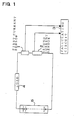
- a device for detecting a current of Fig. 1 Includes: a first current sensor 1 detecting the current with predetermined sampling period; a second current sensor 2 detecting the current with high accuracy with a period longer than the first current sensor 1; and a calculating circuit 3 calculating the current accurately based on the detected currents input from the first current sensor 1 and the second current sensor 2.
- the first current sensor 1 and the second current sensor 2 are connected with each other serially, and are connected with a load 4 serially.
- the first current sensor 1 outputs a digital value of detected signal to the calculating circuit 3 with a sampling period shorter than the second current sensor 2.
- the current sensor 1 is composed of a magnetic current sensor, which detects a current based on magnetic changes.
- the first current sensor may be a type of detecting circuit, which connects a current detecting resistor with low resistance with the load serially, and amplifies the voltage, which is produced between both ends of the current detecting resistor by the current flow, with an amplifier.
- the detected current signal is converted into the digital value of the current signal with the constant sampling period by an A/D converter (not shown).
- the A/D converter converts the current value, which is obtained in sampling with the predetermined period, into the digital value.
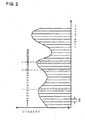
- the A/D converter of the first current sensor 1 shown in the drawing converts the detected current into the digital value with the sampling period of 50 msec, and outputs It to the calculating circuit 3.
- the A/D converter of the first current sensor can convert into the digital value with the sampling period of 50 ⁇ sec - 200 msec for example. It is preferable that it is 1-100 msec. It is more preferable that it is 10-100 msec.
- the first current sensor 1 contains a timer (not shown) specifying the sampling period. The timer outputs a clock signal with constant period to the A/D converter.
- the A/D converter converts the current obtained with sampling based on the clock signal from the timer, and outputs the digital value.
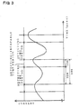
- the second current sensor 2 detects the current with the period longer than the first current sensor 1 though with high accuracy, and converts the current Into the digital value, then outputs it. As shown in Fig. 3, the second current sensor 2 integrates the current during the predetermined time period, and measures the accurate average based on the integrated value, then outputs it as the digital value. As shown in the drawing, though the second current sensor 2 detects the current accurately with the predetermined period, cannot detect the current in all the time period. There is the detecting-incapable time period between the detecting time periods.
- the second current sensor 2 calculates the current based on the current value integrated during the detecting time period, and converts It into the digital value, then further communicates the digital value of the current value with the calculating circuit 3.
- the detecting time period is 350 msec
- the detecting time period and the detecting-incapable time period In the second current sensor 2 are not restricted in these times.
- the detecting time period can be 1.5-1000 times as long as the sampling period in the first current sensor 1. It Is preferable that it is 3-100 times. It is more preferable that it is 5-10 times. Additionally, the detecting-Incapable time period can be 10-100% against the detecting time period.
- the second current sensor 2 of Fig. 3 detects the current, and outputs it to the calculating circuit 3 as the digital value with the period 500 msec, this period does not synchronize with the sampling period of the first current sensor 1.
- the first current sensor 1 and the second current sensor 2 detect the current with constant periods, each of them detects the current, and outputs it outputs to the calculating circuit 3 asynchronously. That is, the first current sensor 1 and the second current sensor 2 output to the calculating circuit 3 with detecting the current independently each other.
- the second current sensor 2 contains a timer (not shown) specifying the timing for detecting the current, this timer outputs a clock signal asynchronously without synchronizing with the timer of the first current sensor 1.
- the second current sensor 2 includes: a current detecting resistor with low resistance connected with the load 4 serially; an amplifier amplifying the voltage produced between both ends of the current detecting resistor; a current detecting circuit calculating the current with accuracy with integrating the output voltage of the amplifier in a constant time period; and an A/D converter A/D-converting the output of the current detecting circuit.
- the current detecting resistor the voltage Is produced proportionately with the current flowed in a battery 5.
- the charge current and the discharge current are opposite in direction to each other in the battery 5, so that the voltages produced at the current detecting resistor in the charge current and the discharge current are also opposite In the polarity to each other.
- the amplifier is provided for reducing the voltage so that the resistance of the current detecting resistor is reduced.
- the accurate current value during the detecting time period can be output to the calculating circuit 3 in the detecting-incapable time period.
- the calculating circuit 3 calculates the digital values of the current signals input from the first current sensor 1 and the second current sensor 2, and calculates the accurate current.
- the current signals are input from the first current sensor 1 and the second current sensor 2 with constant periods, but not synchronized each other.
- the first current sensor 1 outputs the current signal to the calculating circuit 3 with the period of 50 msec.
- the second current sensor 2 outputs the current signal with the period of 500 msec.
- the second current sensor 2 outputs the current signal with the period of 500 msec, the current signal is not the current value during 500 msec.
- the current value of second current sensor 2 is higher accurate than the current value of first current sensor 1, but is not the current value in all the time period.
- the current value during the detecting-Incapable time period, which is incapable of detecting the current by the second current sensor 2, is complemented with the current value detected by the first current sensor 1.
- the calculating circuit 3 compares the detecting current of the second current sensor 2 with the detecting current of the first current sensor 1, and calculates the detecting time period, in which the second current sensor 2 detects the current. Because the time periods detecting the current in the first current sensor 1 and the second current sensor 2 are different; with adjusting the time period, the current values are compared.
- the first current sensor 1 of Fig. 1 detects the current with the sampling period of 50 msec
- the second current sensor 2 of Fig. 3 detects the current during 350 msec. In this case, the time, in which the first current sensor 1 detects seven times continuously, corresponds to the detecting time in the second current sensor 2.
- the average value of the detected values in seven times in the first current sensor 1 is compared with the detected value in the second current sensor 2.
- the times, in which the first current sensor 1 and the second current sensor 2 detect the current agree, the detected current values are equal or the most approximate detected values.
- the second current sensor 2 detects the current with higher accuracy than the first current sensor 1. So that, even the time periods, in which the first current sensor 1 and the second current sensor 2 detect the current, agree, the both detected values in the first current sensor 1 and the second current sensor 2 are not always equal.
- the time periods, in which both of current sensors detect the current agree, the detected values may not be equal though should be the most approximate detected values.
- the calculating circuit 3 determines agreement of the times, in which the first current sensor 1 and the second current sensor 2 detect the current, with comparing the current values of the first current sensor 1 and the second current sensor 2 in consideration of the error, or when the detected values are the most approximate detected values.
- the detecting-Incapable time period is also specified.
- the detecting-incapable time period is 150 msec, so that the first current sensor 1 detects the current three times continuously during this time period. Therefore, the current value during the detecting-incapable time period In the second current sensor 2 is complemented based on detected currents of these three times
- the calculating circuit 3 includes a buffer memory (not shown) storing the current value input from the first current sensor 1 during predetermined time.
- the buffer memory can store at least the current values input from the first current sensor 1 during more than or equal to one cycles of the second current sensor 2. It is preferable that the buffer memory can store the current values output from the first current sensor 1 during the time periods corresponding to more than or equal to 1.5 cycles, for example two cycles.
- the buffer memory stores the detected values output from the first current sensor 1 during 1 sec.
- the time, in which the buffer memory stores Is set the time to include the detecting time period of the second current sensor 2.
- the calculating circuit 3 compares the current values of the first current sensor 1 stored in the buffer memory with the current value input from the second current sensor 2, then specifies the detecting time period of the second current sensor 2 in the first current sensor 1.
- the average value of seven times in the current values of the first current sensor 1 stored in the buffer memory Is compared with the detected value of the second current sensor 2.
- the time width, in which the first current sensor 1 detects the current agrees the time width, In which the second current sensor 2 detects the current.
- the calculating circuit 3 calculates the current value based on the current values of the first current sensor 1 stored in the buffer memory with adjusting the time width in which the second current sensor 2 detects the current, and compares the calculated current value with the detected value of the second current sensor 2.
- the calculating circuit 3 compares the values of the first current sensor 1 and the second current sensor 2, and synchronizes the current signals asynchronous to each other output from the first current sensor 1 and the second current sensor 2. Because the both of the time sampling the current in the first current sensor 1 and the time detecting the current in the second current sensor 2 are specified.
- the calculating circuit 3 complements the current value of the detecting-incapable time period in the second current sensor 2 with the current value of the first current sensor 1.
- the calculating circuit 3 stores the current values Input from the first current sensor 1 into the buffer memory.
- the buffer memory stores the current values Input from the first current sensor 1 during one second repeatedly.
- the first current sensor 1 detects the current value with 50 msec of the sampling period, so that the current values are detected 20 times during one second.
- the current value of the first current sensor 1 stored In the buffer memory includes the current values during the time period corresponding to the detecting time period of the current value input from the second current sensor 2.
- the buffer memory stores the current values of the first current sensor 1 so as to Include the current values corresponding to the detecting time period of the second current sensor 2.
- the calculating circuit 3 calculates the current value with accuracy in all the time based on the detected values of the second current sensor 2 and the first current sensor 1, or the current including the current value even during the detecting-incapable time period of the second current sensor 2, as the flowchart shown in Fig. 4.
- the calculating circuit 3 reads the accurate current value detected by the second current sensor 2.
- the calculating circuit 3 reads the current value detected by the second current sensor 2 every 500 msec.
- the average value S of the current values 10-16 detected by the first current sensor 1 has same time width with average current value of 350 msec, in which the second current sensor 2 detects the current.
- the average value S detected by the first current sensor 1 does not synchronize the time, in which the second current sensor 2 detects the current, so that they are synchronized in the steps below.
- the calculating circuit 3 retains n of the closest average value S to the current value detected by the second current sensor 2.
- the time period detected by the first current sensor 1 synchronizes with the time period detected by the second current sensor 2 based on the value n.
- the calculating circuit 3 complements the current value during the detecting-Incapable time period in the second current sensor 2 with the detected value of the first current sensor 1, so that can detect the continuous current value accurately.
- the calculating circuit 3 calculates the current value more accurately based on the first current sensor 1 and the second current sensor 2.
- the calculating circuit 3 determines whether the current value input from the second current sensor 2 changes continuously or not.
- the second current sensor 2 detects the current under abnormal condition, the current value changes sharply. Therefore, it is confirmed whether the detected value of the second current sensor 2 changes sharply or not, that is whether the second current sensor 2 detects the current under normal condition.
- the calculating circuit 3 compares the detected value of the second current sensor 2 with the average S of the first current sensor 1, and determines whether the difference between them is large or not.
- the difference between the detected value of the second current sensor 2 and the average S of the first current sensor 1 is large.
- the detected value of the second current sensor 2 does not change continuously, or the difference between the detected value of the second current sensor 2 and the average S of the first current sensor 1 is large; the detected value of the second current sensor 2 Is not selected, and the current is detected with replacing the average S of the first current sensor 1. That is, the detection of the second current sensor 2 Is cancelled, and the detected value of the first current sensor 1 is selected.
- the second current sensor 2 detects the current under normal condition, as the above method, the current during the detecting-incapable time period In the second current sensor 2 Is complemented with the current value of the first current sensor 1.
Landscapes
- Physics & Mathematics (AREA)
- General Physics & Mathematics (AREA)
- Measurement Of Current Or Voltage (AREA)
- Secondary Cells (AREA)
Applications Claiming Priority (2)
| Application Number | Priority Date | Filing Date | Title |
|---|---|---|---|
| JP2002026172 | 2002-02-01 | ||
| JP2002026172A JP2003227852A (ja) | 2002-02-01 | 2002-02-01 | 電流検出方法と電流検出装置 |
Publications (2)
| Publication Number | Publication Date |
|---|---|
| EP1333291A1 true EP1333291A1 (de) | 2003-08-06 |
| EP1333291B1 EP1333291B1 (de) | 2008-06-25 |
Family
ID=19192337
Family Applications (1)
| Application Number | Title | Priority Date | Filing Date |
|---|---|---|---|
| EP03001945A Expired - Fee Related EP1333291B1 (de) | 2002-02-01 | 2003-01-30 | Verfahren und Vorrichtung zur Stromerfassung |
Country Status (6)
| Country | Link |
|---|---|
| US (1) | US6768310B2 (de) |
| EP (1) | EP1333291B1 (de) |
| JP (1) | JP2003227852A (de) |
| KR (1) | KR20030066306A (de) |
| CN (1) | CN1295516C (de) |
| DE (1) | DE60321733D1 (de) |
Cited By (3)
| Publication number | Priority date | Publication date | Assignee | Title |
|---|---|---|---|---|
| WO2005031955A1 (en) * | 2003-09-25 | 2005-04-07 | Koninklijke Philips Electronics N.V. | A switch mode power supply |
| EP2472700A1 (de) * | 2009-08-27 | 2012-07-04 | Toyota Jidosha Kabushiki Kaisha | Ladesteuerungsvorrichtung für ein fahrzeug und damit ausgestattetes elektrofahrzeug |
| EP2557426A3 (de) * | 2011-08-08 | 2013-12-04 | Lenze Automation Gmbh | Verfahren zum Messen eines mittels eines Frequenzumrichters erzeugten analogen Signals |
Families Citing this family (10)
| Publication number | Priority date | Publication date | Assignee | Title |
|---|---|---|---|---|
| US7230413B2 (en) * | 2004-10-19 | 2007-06-12 | Siemens Energy & Automation, Inc. | Flexible current sensor |
| JP5212887B2 (ja) * | 2007-10-17 | 2013-06-19 | 横河電機株式会社 | 電流検出装置 |
| JP2009080123A (ja) * | 2008-10-31 | 2009-04-16 | Elpida Memory Inc | デジタル測定器及び測定方法 |
| US9203300B2 (en) * | 2009-05-20 | 2015-12-01 | Alex Mevay | Systems and methods for controlling power converters |
| US20110276289A1 (en) * | 2010-05-07 | 2011-11-10 | Samsung Electronics Co., Ltd. | Power monitoring apparatus for household appliance |
| JP5780107B2 (ja) * | 2011-10-19 | 2015-09-16 | トヨタ自動車株式会社 | 蓄電システム及び電流センサ異常を検出する方法 |
| WO2013158754A1 (en) * | 2012-04-17 | 2013-10-24 | Georgia Tech Research Corporation | Voltage sensor systems and methods |
| JP6220904B2 (ja) * | 2016-01-14 | 2017-10-25 | 本田技研工業株式会社 | 蓄電装置 |
| JP6544310B2 (ja) * | 2016-07-14 | 2019-07-17 | 株式会社デンソー | 電池監視システム |
| US20210270906A1 (en) * | 2020-02-27 | 2021-09-02 | O2Micro, Inc. | Battery management controllers capable of determining estimate of state of charge |
Citations (3)
| Publication number | Priority date | Publication date | Assignee | Title |
|---|---|---|---|---|
| JPH07322494A (ja) * | 1994-05-25 | 1995-12-08 | Seiko Denki Seisakusho:Kk | 力率調整及び電圧調整機能を備えた多出力変換器 |
| US5867054A (en) * | 1997-07-31 | 1999-02-02 | National Semiconductor Corporation | Current sensing circuit |
| JP2001166019A (ja) * | 1999-12-09 | 2001-06-22 | Mitsubishi Motors Corp | バッテリの充電状態判定装置 |
Family Cites Families (8)
| Publication number | Priority date | Publication date | Assignee | Title |
|---|---|---|---|---|
| JP2951196B2 (ja) * | 1994-03-23 | 1999-09-20 | 三洋電機株式会社 | バッテリ残量検出用電流検出装置 |
| JP4142124B2 (ja) * | 1996-06-20 | 2008-08-27 | 矢崎総業株式会社 | 車両用電源供給装置及び該装置における異常検出装置 |
| US6590396B1 (en) * | 1999-01-19 | 2003-07-08 | Battery Alert, Ltd. | Device and method for indicating in-use charging and abnormal discharging of a combustion engine battery following engine turn-off |
| JP3488136B2 (ja) * | 1999-05-26 | 2004-01-19 | 矢崎総業株式会社 | バッテリの残存容量測定装置 |
| US6501249B1 (en) * | 1999-10-13 | 2002-12-31 | Xicor, Inc. | Battery management system |
| JP3736268B2 (ja) * | 2000-03-21 | 2006-01-18 | 日産自動車株式会社 | ハイブリッド車両の制御装置 |
| US6320339B1 (en) * | 2000-09-12 | 2001-11-20 | Universal Scientific Industrial Co., Ltd. | Control device for controlling current passing through a motor |
| US6424129B1 (en) * | 2001-08-21 | 2002-07-23 | Semtech Corporation | Method and apparatus for accurately sensing output current in a DC-to-DC voltage converter |
-
2002
- 2002-02-01 JP JP2002026172A patent/JP2003227852A/ja active Pending
- 2002-12-11 KR KR1020020078839A patent/KR20030066306A/ko not_active Application Discontinuation
-
2003
- 2003-01-28 CN CNB031034195A patent/CN1295516C/zh not_active Expired - Fee Related
- 2003-01-30 EP EP03001945A patent/EP1333291B1/de not_active Expired - Fee Related
- 2003-01-30 DE DE60321733T patent/DE60321733D1/de not_active Expired - Fee Related
- 2003-01-31 US US10/354,975 patent/US6768310B2/en not_active Expired - Fee Related
Patent Citations (3)
| Publication number | Priority date | Publication date | Assignee | Title |
|---|---|---|---|---|
| JPH07322494A (ja) * | 1994-05-25 | 1995-12-08 | Seiko Denki Seisakusho:Kk | 力率調整及び電圧調整機能を備えた多出力変換器 |
| US5867054A (en) * | 1997-07-31 | 1999-02-02 | National Semiconductor Corporation | Current sensing circuit |
| JP2001166019A (ja) * | 1999-12-09 | 2001-06-22 | Mitsubishi Motors Corp | バッテリの充電状態判定装置 |
Non-Patent Citations (2)
| Title |
|---|
| PATENT ABSTRACTS OF JAPAN vol. 1996, no. 04 30 April 1996 (1996-04-30) * |
| PATENT ABSTRACTS OF JAPAN vol. 2000, no. 23 10 February 2001 (2001-02-10) * |
Cited By (4)
| Publication number | Priority date | Publication date | Assignee | Title |
|---|---|---|---|---|
| WO2005031955A1 (en) * | 2003-09-25 | 2005-04-07 | Koninklijke Philips Electronics N.V. | A switch mode power supply |
| EP2472700A1 (de) * | 2009-08-27 | 2012-07-04 | Toyota Jidosha Kabushiki Kaisha | Ladesteuerungsvorrichtung für ein fahrzeug und damit ausgestattetes elektrofahrzeug |
| EP2472700A4 (de) * | 2009-08-27 | 2013-05-08 | Toyota Motor Co Ltd | Ladesteuerungsvorrichtung für ein fahrzeug und damit ausgestattetes elektrofahrzeug |
| EP2557426A3 (de) * | 2011-08-08 | 2013-12-04 | Lenze Automation Gmbh | Verfahren zum Messen eines mittels eines Frequenzumrichters erzeugten analogen Signals |
Also Published As
| Publication number | Publication date |
|---|---|
| US6768310B2 (en) | 2004-07-27 |
| DE60321733D1 (de) | 2008-08-07 |
| EP1333291B1 (de) | 2008-06-25 |
| KR20030066306A (ko) | 2003-08-09 |
| CN1435694A (zh) | 2003-08-13 |
| US20030146756A1 (en) | 2003-08-07 |
| CN1295516C (zh) | 2007-01-17 |
| JP2003227852A (ja) | 2003-08-15 |
Similar Documents
| Publication | Publication Date | Title |
|---|---|---|
| US10916813B2 (en) | Battery management apparatus and method for calibrating a state of charge of a battery | |
| US6768310B2 (en) | Method and device for detecting a current | |
| WO2012105492A1 (ja) | 電池の満充電容量検出方法 | |
| JP5273794B2 (ja) | 二次電池のsoc値を推定する方法及び装置並びに劣化判定方法及び装置 | |
| EP1906193B1 (de) | Verfahren und einrichtung zum erkennen des ladungszustands einer batterie | |
| US7078907B2 (en) | Battery capacity calculating method, battery capacity calculating apparatus and battery capacity calculating program | |
| US9026389B2 (en) | State of charge computation system | |
| US7129707B2 (en) | Apparatus for judging state of assembled battery | |
| US8332169B2 (en) | Apparatus and method for estimating state of health of battery based on battery voltage variation pattern | |
| US5451881A (en) | Method and means for adjusting battery monitor based on rate of current drawn from the battery | |
| US20160131720A1 (en) | Device for estimating state of health of battery, and state of health estimation method for battery | |
| EP1975636A2 (de) | Verfahren zur Bestimmung der Kapazität einer vollgeladenen Batterie | |
| CN102762995A (zh) | 电池状态检测装置 | |
| JPWO2008026476A1 (ja) | 二次電池のsoc値を推定する方法及び装置並びに劣化判定方法及び装置 | |
| KR20010043872A (ko) | 전지 충전상태의 추정수단 및 전지 열화상태의 추정방법 | |
| EP2439550A1 (de) | Kalkulationsvorrichtung für batterieladezustand | |
| JP3453821B2 (ja) | 電池残存容量計測装置 | |
| US20110311850A1 (en) | Secondary battery device | |
| US5614829A (en) | State-of-charge measuring method using multilevel peukert's equation | |
| EP1736789A1 (de) | Verfahren und geräte zur schätzung der restkapazität einer speicherbatterie | |
| CN116008841A (zh) | 电池的健康状态(soh)估算方法 | |
| JP2010002374A (ja) | 電池パック | |
| JP2003282157A (ja) | リチウム二次電池用制御回路 | |
| AU2023213443A1 (en) | Battery SOC estimating apparatus and method | |
| JPH05180914A (ja) | 蓄電池残存容量の計測システム |
Legal Events
| Date | Code | Title | Description |
|---|---|---|---|
| PUAI | Public reference made under article 153(3) epc to a published international application that has entered the european phase |
Free format text: ORIGINAL CODE: 0009012 |
|
| AK | Designated contracting states |
Designated state(s): AT BE BG CH CY CZ DE DK EE ES FI FR GB GR HU IE IT LI LU MC NL PT SE SI SK TR |
|
| AX | Request for extension of the european patent |
Extension state: AL LT LV MK RO |
|
| 17P | Request for examination filed |
Effective date: 20030814 |
|
| AKX | Designation fees paid |
Designated state(s): DE FR GB |
|
| 17Q | First examination report despatched |
Effective date: 20061130 |
|
| GRAP | Despatch of communication of intention to grant a patent |
Free format text: ORIGINAL CODE: EPIDOSNIGR1 |
|
| GRAS | Grant fee paid |
Free format text: ORIGINAL CODE: EPIDOSNIGR3 |
|
| GRAA | (expected) grant |
Free format text: ORIGINAL CODE: 0009210 |
|
| AK | Designated contracting states |
Kind code of ref document: B1 Designated state(s): DE FR GB |
|
| REG | Reference to a national code |
Ref country code: GB Ref legal event code: FG4D |
|
| REF | Corresponds to: |
Ref document number: 60321733 Country of ref document: DE Date of ref document: 20080807 Kind code of ref document: P |
|
| PLBE | No opposition filed within time limit |
Free format text: ORIGINAL CODE: 0009261 |
|
| STAA | Information on the status of an ep patent application or granted ep patent |
Free format text: STATUS: NO OPPOSITION FILED WITHIN TIME LIMIT |
|
| PGFP | Annual fee paid to national office [announced via postgrant information from national office to epo] |
Ref country code: DE Payment date: 20090128 Year of fee payment: 7 |
|
| 26N | No opposition filed |
Effective date: 20090326 |
|
| PGFP | Annual fee paid to national office [announced via postgrant information from national office to epo] |
Ref country code: GB Payment date: 20090123 Year of fee payment: 7 |
|
| PGFP | Annual fee paid to national office [announced via postgrant information from national office to epo] |
Ref country code: FR Payment date: 20090120 Year of fee payment: 7 |
|
| GBPC | Gb: european patent ceased through non-payment of renewal fee |
Effective date: 20100130 |
|
| REG | Reference to a national code |
Ref country code: FR Ref legal event code: ST Effective date: 20100930 |
|
| PG25 | Lapsed in a contracting state [announced via postgrant information from national office to epo] |
Ref country code: FR Free format text: LAPSE BECAUSE OF NON-PAYMENT OF DUE FEES Effective date: 20100201 |
|
| PG25 | Lapsed in a contracting state [announced via postgrant information from national office to epo] |
Ref country code: DE Free format text: LAPSE BECAUSE OF NON-PAYMENT OF DUE FEES Effective date: 20100803 |
|
| PG25 | Lapsed in a contracting state [announced via postgrant information from national office to epo] |
Ref country code: GB Free format text: LAPSE BECAUSE OF NON-PAYMENT OF DUE FEES Effective date: 20100130 |