EP1333236A1 - Kühl- und/oder Gefriergerät - Google Patents
Kühl- und/oder Gefriergerät Download PDFInfo
- Publication number
- EP1333236A1 EP1333236A1 EP02023720A EP02023720A EP1333236A1 EP 1333236 A1 EP1333236 A1 EP 1333236A1 EP 02023720 A EP02023720 A EP 02023720A EP 02023720 A EP02023720 A EP 02023720A EP 1333236 A1 EP1333236 A1 EP 1333236A1
- Authority
- EP
- European Patent Office
- Prior art keywords
- motors
- refrigerator
- compressor
- phase
- parallel
- Prior art date
- Legal status (The legal status is an assumption and is not a legal conclusion. Google has not performed a legal analysis and makes no representation as to the accuracy of the status listed.)
- Granted
Links
Images
Classifications
-
- F—MECHANICAL ENGINEERING; LIGHTING; HEATING; WEAPONS; BLASTING
- F25—REFRIGERATION OR COOLING; COMBINED HEATING AND REFRIGERATION SYSTEMS; HEAT PUMP SYSTEMS; MANUFACTURE OR STORAGE OF ICE; LIQUEFACTION SOLIDIFICATION OF GASES
- F25B—REFRIGERATION MACHINES, PLANTS OR SYSTEMS; COMBINED HEATING AND REFRIGERATION SYSTEMS; HEAT PUMP SYSTEMS
- F25B49/00—Arrangement or mounting of control or safety devices
- F25B49/02—Arrangement or mounting of control or safety devices for compression type machines, plants or systems
- F25B49/025—Motor control arrangements
-
- F—MECHANICAL ENGINEERING; LIGHTING; HEATING; WEAPONS; BLASTING
- F25—REFRIGERATION OR COOLING; COMBINED HEATING AND REFRIGERATION SYSTEMS; HEAT PUMP SYSTEMS; MANUFACTURE OR STORAGE OF ICE; LIQUEFACTION SOLIDIFICATION OF GASES
- F25B—REFRIGERATION MACHINES, PLANTS OR SYSTEMS; COMBINED HEATING AND REFRIGERATION SYSTEMS; HEAT PUMP SYSTEMS
- F25B2400/00—Component parts or details not otherwise provided for in this subclass
- F25B2400/06—Several compression cycles arranged in parallel
-
- F—MECHANICAL ENGINEERING; LIGHTING; HEATING; WEAPONS; BLASTING
- F25—REFRIGERATION OR COOLING; COMBINED HEATING AND REFRIGERATION SYSTEMS; HEAT PUMP SYSTEMS; MANUFACTURE OR STORAGE OF ICE; LIQUEFACTION SOLIDIFICATION OF GASES
- F25B—REFRIGERATION MACHINES, PLANTS OR SYSTEMS; COMBINED HEATING AND REFRIGERATION SYSTEMS; HEAT PUMP SYSTEMS
- F25B2500/00—Problems to be solved
- F25B2500/26—Problems to be solved characterised by the startup of the refrigeration cycle
-
- F—MECHANICAL ENGINEERING; LIGHTING; HEATING; WEAPONS; BLASTING
- F25—REFRIGERATION OR COOLING; COMBINED HEATING AND REFRIGERATION SYSTEMS; HEAT PUMP SYSTEMS; MANUFACTURE OR STORAGE OF ICE; LIQUEFACTION SOLIDIFICATION OF GASES
- F25B—REFRIGERATION MACHINES, PLANTS OR SYSTEMS; COMBINED HEATING AND REFRIGERATION SYSTEMS; HEAT PUMP SYSTEMS
- F25B2600/00—Control issues
- F25B2600/02—Compressor control
- F25B2600/021—Inverters therefor
-
- F—MECHANICAL ENGINEERING; LIGHTING; HEATING; WEAPONS; BLASTING
- F25—REFRIGERATION OR COOLING; COMBINED HEATING AND REFRIGERATION SYSTEMS; HEAT PUMP SYSTEMS; MANUFACTURE OR STORAGE OF ICE; LIQUEFACTION SOLIDIFICATION OF GASES
- F25D—REFRIGERATORS; COLD ROOMS; ICE-BOXES; COOLING OR FREEZING APPARATUS NOT OTHERWISE PROVIDED FOR
- F25D11/00—Self-contained movable devices, e.g. domestic refrigerators
- F25D11/02—Self-contained movable devices, e.g. domestic refrigerators with cooling compartments at different temperatures
-
- F—MECHANICAL ENGINEERING; LIGHTING; HEATING; WEAPONS; BLASTING
- F25—REFRIGERATION OR COOLING; COMBINED HEATING AND REFRIGERATION SYSTEMS; HEAT PUMP SYSTEMS; MANUFACTURE OR STORAGE OF ICE; LIQUEFACTION SOLIDIFICATION OF GASES
- F25D—REFRIGERATORS; COLD ROOMS; ICE-BOXES; COOLING OR FREEZING APPARATUS NOT OTHERWISE PROVIDED FOR
- F25D2400/00—General features of, or devices for refrigerators, cold rooms, ice-boxes, or for cooling or freezing apparatus not covered by any other subclass
- F25D2400/14—Refrigerator multi units
-
- Y—GENERAL TAGGING OF NEW TECHNOLOGICAL DEVELOPMENTS; GENERAL TAGGING OF CROSS-SECTIONAL TECHNOLOGIES SPANNING OVER SEVERAL SECTIONS OF THE IPC; TECHNICAL SUBJECTS COVERED BY FORMER USPC CROSS-REFERENCE ART COLLECTIONS [XRACs] AND DIGESTS
- Y02—TECHNOLOGIES OR APPLICATIONS FOR MITIGATION OR ADAPTATION AGAINST CLIMATE CHANGE
- Y02B—CLIMATE CHANGE MITIGATION TECHNOLOGIES RELATED TO BUILDINGS, e.g. HOUSING, HOUSE APPLIANCES OR RELATED END-USER APPLICATIONS
- Y02B30/00—Energy efficient heating, ventilation or air conditioning [HVAC]
- Y02B30/70—Efficient control or regulation technologies, e.g. for control of refrigerant flow, motor or heating
-
- Y—GENERAL TAGGING OF NEW TECHNOLOGICAL DEVELOPMENTS; GENERAL TAGGING OF CROSS-SECTIONAL TECHNOLOGIES SPANNING OVER SEVERAL SECTIONS OF THE IPC; TECHNICAL SUBJECTS COVERED BY FORMER USPC CROSS-REFERENCE ART COLLECTIONS [XRACs] AND DIGESTS
- Y02—TECHNOLOGIES OR APPLICATIONS FOR MITIGATION OR ADAPTATION AGAINST CLIMATE CHANGE
- Y02B—CLIMATE CHANGE MITIGATION TECHNOLOGIES RELATED TO BUILDINGS, e.g. HOUSING, HOUSE APPLIANCES OR RELATED END-USER APPLICATIONS
- Y02B40/00—Technologies aiming at improving the efficiency of home appliances, e.g. induction cooking or efficient technologies for refrigerators, freezers or dish washers
Definitions
- the invention relates to a refrigerator and / or freezer with two refrigeration circuits each with an evaporator, a condenser and a compressor Compressor motor has, preferably combination device with a cooling section and a freezer compartment.
- Combination units with a refrigerator and a freezer with two compressors have the advantage that the refrigerator compartment and the freezer compartment are separate are adjustable and can also be switched off. To save energy, it is with cooling and Freezers known to use variable-speed compressor motors. This is however, in combination devices with two compressor motors made of design and cost reasons inappropriate.
- the object of the invention is therefore to take advantage of combination devices with two Compressors and compressor motors with the advantages of speed-controlled To connect compressor motors while maintaining a reasonable cost.
- Single-phase asynchronous motors are usually capacitor motors with a capacitor circuit the auxiliary phase.
- Such motors can be motors with starting capacitor, motors with operating capacitor or double capacitor motors act.
- Starting devices are also known in which instead of a PTC resistor an electronic circuit effecting the starting conditions is used. Furthermore, starting devices with current relays and speed measurement are known.
- Double condenser motors unite through the combination of starting and operating capacitors the advantages during start-up and nominal operation.
- the compressor motors are expediently single-phase asynchronous motors a main and auxiliary winding and an operating capacitor.
- the main and Auxiliary winding can also be designed identically.
- the compressor motors have at least one main and an auxiliary winding, the phase-shifted AC currents are supplied from two outputs of the variable frequency converter become.
- the compressor motors can also be three-phase asynchronous motors act in parallel to each other to the three phases of a variable frequency converter can be switched on.
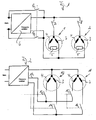
- asynchronous motors 1, 2 with a main winding 3, an auxiliary winding 4 and a starting device 5 can be seen, each for itself alone or together in parallel to the frequency converter 6 with variable frequency or can also be connected directly to the network.
- the starting device 5 consists in the usual way of a parallel connection of Operating capacitor and a PTC resistor (resistor with positive temperature coefficient).
- a PTC resistor resistor with positive temperature coefficient
- the variable frequency converter 6 has two outputs, one of which Frequency output constantly with the one terminals of the single-phase asynchronous motors 1, 2 is connected.
- the other terminals of the single-phase asynchronous motors 1, 2 can optionally via switches 7, 8 to the second output of the frequency converter be turned on.
- the frequency converter is also bridged to the mains Switch 9 provided.
- FIG. 2 differs from that of FIG. 1 in that that the windings 4 do not have an operating or starting capacitor, but through a special third output 12 of the variable frequency converter can be fed with a phase-shifted alternating current.
- the and closing switches 13, 14 and 15, 16 are provided, through which the windings of the Motors connected to the two frequency outputs of the frequency converter can be while another output of the frequency converter is constantly on the corresponding terminals of the motors 10, 11 is switched on.
Landscapes
- Engineering & Computer Science (AREA)
- Physics & Mathematics (AREA)
- Mechanical Engineering (AREA)
- Thermal Sciences (AREA)
- General Engineering & Computer Science (AREA)
- Control Of Multiple Motors (AREA)
- Fats And Perfumes (AREA)
- Control Of Ac Motors In General (AREA)
Abstract
Description
- Fig. 1
- die Anschaltung von zwei Einphasenasynchronmotoren parallel zueinander an einen variablen Frequenzumrichter oder das Netz in einem Prinzipschaltbild und
- Fig. 2
- die Anschaltung von zwei Asynchronmotoren parallel zueinander an drei Ausgänge eines variablen Frequenzumrichters in einer Prinzipskizze.
Claims (7)
- Kühl- und/oder Gefriergerät mit zwei Kältekreisläufen, von denen jeder einen Verdampfer, einen Kondensator und einen Kompressor mit Kompressormotor besitzt, vorzugsweise Kombinationsgerät mit einem Kühlteil und einem Gefrierteil,
dadurch gekennzeichnet, daß die beiden Kompressormotore des Asynchrontyps durch Stellglieder, z. B. Relais, parallel zueinander an einen Frequenzumrichter mit variabel einstellbarer Frequenz anschaltbar sind. - Kühl- und/oder Gefriergerät nach Anspruch 1, dadurch gekennzeichnet, daß die Kompressormotore Einphasenasynchronmotore mit jeweils zwei Wicklungen und mit einer Anlaufvorrichtung sind.
- Kühl- und/oder Gefriergerät nach Anspruch 1 oder 2, dadurch gekennzeichnet, daß der Einphasensynchronmotor mit einem Betriebskondensator versehen ist.
- Kühl- und/oder Gefriergerät nach Anspruch 1, dadurch gekennzeichnet, daß die Kompressormotore mindestens eine Haupt- und eine Hilfswicklung aufweisen, die an die Phasenausgänge eines gemeinsamen Phasenumrichters anschaltbar sind (Fig. 2).
- Kühl- und/oder Gefriergerät nach Anspruch 4, dadurch gekennzeichnet, daß die Haupt- und Hilfswicklung identisch ausgebildet sind.
- Kühl- und/oder Gefriergerät nach Anspruch 1, dadurch gekennzeichnet, daß die Kompressormotore Dreiphasenasynchronmotore sind, die parallel an die drei Phasenausgänge eines gemeinsamen Phasenumrichters anschaltbar sind.
- Kühl- und/oder Gefriergerät nach Anspruche 1, dadurch gekennzeichnet, daß Schalter vorgesehen sind, durch die die Motore unter Umgehung des Frequenzumrichters einzeln oder parallel zueinander unmittelbar an das Netz anschaltbar sind.
Applications Claiming Priority (4)
| Application Number | Priority Date | Filing Date | Title |
|---|---|---|---|
| DE20201459U | 2002-01-31 | ||
| DE20201459 | 2002-01-31 | ||
| DE20205224U | 2002-04-04 | ||
| DE20205224U DE20205224U1 (de) | 2002-01-31 | 2002-04-04 | Kühl- und/oder Gefriergerät |
Publications (2)
| Publication Number | Publication Date |
|---|---|
| EP1333236A1 true EP1333236A1 (de) | 2003-08-06 |
| EP1333236B1 EP1333236B1 (de) | 2008-03-19 |
Family
ID=26057367
Family Applications (1)
| Application Number | Title | Priority Date | Filing Date |
|---|---|---|---|
| EP02023720A Expired - Lifetime EP1333236B1 (de) | 2002-01-31 | 2002-10-23 | Kühl- und/oder Gefriergerät |
Country Status (4)
| Country | Link |
|---|---|
| EP (1) | EP1333236B1 (de) |
| AT (1) | ATE389855T1 (de) |
| DE (1) | DE50211917D1 (de) |
| ES (1) | ES2300411T3 (de) |
Cited By (2)
| Publication number | Priority date | Publication date | Assignee | Title |
|---|---|---|---|---|
| EP1990591A1 (de) * | 2007-05-08 | 2008-11-12 | Sorgenia S.P.A. | Unabhängige Universalvorrichtung zur Steuerung der Drehzahl eines motorbetriebenen Kompressors von Haushaltskühlgeräten und Steuerverfahren dafür |
| EP2126477A4 (de) * | 2006-12-29 | 2012-07-11 | Carrier Corp | Reservekompressor mit variabler frequenz |
Families Citing this family (1)
| Publication number | Priority date | Publication date | Assignee | Title |
|---|---|---|---|---|
| DE102008053822B3 (de) * | 2008-10-27 | 2010-06-17 | Siemens Aktiengesellschaft | Vorrichtung und Verfahren zur Speisung eines Abnehmernetzes mit der elektrischen Leistung eines Versorgungsnetzes |
Citations (6)
| Publication number | Priority date | Publication date | Assignee | Title |
|---|---|---|---|---|
| JPS59221546A (ja) * | 1983-05-30 | 1984-12-13 | Toshiba Corp | 空気調和機 |
| JPS6213950A (ja) * | 1985-07-10 | 1987-01-22 | Daikin Ind Ltd | 空気調和装置 |
| EP0442848A2 (de) * | 1990-02-14 | 1991-08-21 | Giuseppe Torchio | Wechselstromantrieb veränderbarer Gescwindigkeit mit einem einen Kurzschlussrotor verwendenden Induktionsmotor |
| US5796234A (en) * | 1996-01-19 | 1998-08-18 | Gas Research Institute | Variable speed motor apparatus and method for forming same from a split capacitor motor |
| US6185946B1 (en) * | 1999-05-07 | 2001-02-13 | Thomas B. Hartman | System for sequencing chillers in a loop cooling plant and other systems that employ all variable-speed units |
| EP1184631A1 (de) * | 2000-08-31 | 2002-03-06 | Carrier Corporation | Verfahren zur Regelung eines Antriebs mit variabler Drehzahl bei mehrfachen Kühleinheiten |
-
2002
- 2002-10-23 EP EP02023720A patent/EP1333236B1/de not_active Expired - Lifetime
- 2002-10-23 ES ES02023720T patent/ES2300411T3/es not_active Expired - Lifetime
- 2002-10-23 DE DE50211917T patent/DE50211917D1/de not_active Expired - Lifetime
- 2002-10-23 AT AT02023720T patent/ATE389855T1/de not_active IP Right Cessation
Patent Citations (6)
| Publication number | Priority date | Publication date | Assignee | Title |
|---|---|---|---|---|
| JPS59221546A (ja) * | 1983-05-30 | 1984-12-13 | Toshiba Corp | 空気調和機 |
| JPS6213950A (ja) * | 1985-07-10 | 1987-01-22 | Daikin Ind Ltd | 空気調和装置 |
| EP0442848A2 (de) * | 1990-02-14 | 1991-08-21 | Giuseppe Torchio | Wechselstromantrieb veränderbarer Gescwindigkeit mit einem einen Kurzschlussrotor verwendenden Induktionsmotor |
| US5796234A (en) * | 1996-01-19 | 1998-08-18 | Gas Research Institute | Variable speed motor apparatus and method for forming same from a split capacitor motor |
| US6185946B1 (en) * | 1999-05-07 | 2001-02-13 | Thomas B. Hartman | System for sequencing chillers in a loop cooling plant and other systems that employ all variable-speed units |
| EP1184631A1 (de) * | 2000-08-31 | 2002-03-06 | Carrier Corporation | Verfahren zur Regelung eines Antriebs mit variabler Drehzahl bei mehrfachen Kühleinheiten |
Non-Patent Citations (3)
| Title |
|---|
| PATENT ABSTRACTS OF JAPAN vol. 009, no. 098 (M - 375) 27 April 1985 (1985-04-27) * |
| PATENT ABSTRACTS OF JAPAN vol. 011, no. 188 (M - 599) 17 June 1987 (1987-06-17) * |
| PATENT ABSTRACTS OF JAPAN vol. 2000, no. 18 5 June 2001 (2001-06-05) * |
Cited By (2)
| Publication number | Priority date | Publication date | Assignee | Title |
|---|---|---|---|---|
| EP2126477A4 (de) * | 2006-12-29 | 2012-07-11 | Carrier Corp | Reservekompressor mit variabler frequenz |
| EP1990591A1 (de) * | 2007-05-08 | 2008-11-12 | Sorgenia S.P.A. | Unabhängige Universalvorrichtung zur Steuerung der Drehzahl eines motorbetriebenen Kompressors von Haushaltskühlgeräten und Steuerverfahren dafür |
Also Published As
| Publication number | Publication date |
|---|---|
| ES2300411T3 (es) | 2008-06-16 |
| ATE389855T1 (de) | 2008-04-15 |
| DE50211917D1 (de) | 2008-04-30 |
| EP1333236B1 (de) | 2008-03-19 |
Similar Documents
| Publication | Publication Date | Title |
|---|---|---|
| DE69329176T2 (de) | Motor-Antriebsvorrichtung und Verfahren | |
| DE69212345T2 (de) | Wechselstrommotorantriebssystem | |
| EP0989666A1 (de) | System zur Drehzahlsteuerung von Wechselstrom-Motoren | |
| DE3879663T2 (de) | Kondensatormotor mit reihenresonanz. | |
| EP0131815A1 (de) | Wechselstrommaschinenantrieb | |
| EP1538337A1 (de) | Anordnung zum Überlastschutz und Verfahren zur Reduktion des Stromverbrauchs bei Netzspannungsschwankungen | |
| EP1160523A2 (de) | Einrichtung zum Antrieb eines Klimakompressors | |
| WO2019015812A1 (de) | Steuerungselektronik für kältetechnische anlagen | |
| DE102019130822A1 (de) | Antrieb mit variabler frequenz mit integriertem front-end-gleichrichter und bypass | |
| EP1333236B1 (de) | Kühl- und/oder Gefriergerät | |
| DE4322223A1 (de) | Regelungseinrichtung für einen Verdichtermotor eines Kühl- und/oder Gefriergeräts | |
| DE20205224U1 (de) | Kühl- und/oder Gefriergerät | |
| DE10302481B4 (de) | Antriebsvorrichtung für einen Motor | |
| DE2615768A1 (de) | Von einem asynchronmotor angetriebene arbeitsmaschine mit wechselndem drehmomentbedarf, insbesondere verdichter fuer kaelteaggregate von haushaltskuehlschraenken o.dgl. | |
| EP0583560A2 (de) | Für Einphasenwechselstrom-Anschluss ausgestattetes Kühl- und/oder Gefriergerät | |
| DE102017126632A1 (de) | Kühl- und/oder Gefriergerät | |
| DE102006007266A1 (de) | Starter für einen Elektromotor | |
| DE3630604A1 (de) | Anlaufsteuerschaltung | |
| DE710024C (de) | Schaltung fuer den Anschluss von Drehstrommotoren an Einphasennetze | |
| DE2736370C2 (de) | Kühlmöbel-Kombination, insbesondere Kühl-Gefrier-Kombination | |
| DE102004012635B4 (de) | Kältesystem und Verfahren zum Betreiben eines Kältesystems | |
| AT406213B (de) | Schaltung zum steuern des hochlaufes eines einphasigen asynchronmotors | |
| DE20113805U1 (de) | Kühl- und Gefriergerät | |
| DE19509365C2 (de) | Oberwellenfreie Anlaufsteuerung für Drehstromasynchronmotoren | |
| DE602004003525T2 (de) | Vorrichtung aus Elektromotor und Drehzahlsteuerung |
Legal Events
| Date | Code | Title | Description |
|---|---|---|---|
| PUAI | Public reference made under article 153(3) epc to a published international application that has entered the european phase |
Free format text: ORIGINAL CODE: 0009012 |
|
| 17P | Request for examination filed |
Effective date: 20030402 |
|
| AK | Designated contracting states |
Designated state(s): AT BE BG CH CY CZ DE DK EE ES FI FR GB GR IE IT LI LU MC NL PT SE SK TR |
|
| AX | Request for extension of the european patent |
Extension state: AL LT LV MK RO SI |
|
| AKX | Designation fees paid |
Designated state(s): AT BE BG CH CY CZ DE DK EE ES FI FR GB GR IE IT LI LU MC NL PT SE SK TR |
|
| 17Q | First examination report despatched |
Effective date: 20061124 |
|
| GRAP | Despatch of communication of intention to grant a patent |
Free format text: ORIGINAL CODE: EPIDOSNIGR1 |
|
| GRAS | Grant fee paid |
Free format text: ORIGINAL CODE: EPIDOSNIGR3 |
|
| GRAA | (expected) grant |
Free format text: ORIGINAL CODE: 0009210 |
|
| AK | Designated contracting states |
Kind code of ref document: B1 Designated state(s): AT BE BG CH CY CZ DE DK EE ES FI FR GB GR IE IT LI LU MC NL PT SE SK TR |
|
| REG | Reference to a national code |
Ref country code: GB Ref legal event code: FG4D Free format text: NOT ENGLISH |
|
| REG | Reference to a national code |
Ref country code: CH Ref legal event code: EP |
|
| REF | Corresponds to: |
Ref document number: 50211917 Country of ref document: DE Date of ref document: 20080430 Kind code of ref document: P |
|
| REG | Reference to a national code |
Ref country code: IE Ref legal event code: FG4D Free format text: LANGUAGE OF EP DOCUMENT: GERMAN |
|
| REG | Reference to a national code |
Ref country code: ES Ref legal event code: FG2A Ref document number: 2300411 Country of ref document: ES Kind code of ref document: T3 |
|
| PG25 | Lapsed in a contracting state [announced via postgrant information from national office to epo] |
Ref country code: FI Free format text: LAPSE BECAUSE OF FAILURE TO SUBMIT A TRANSLATION OF THE DESCRIPTION OR TO PAY THE FEE WITHIN THE PRESCRIBED TIME-LIMIT Effective date: 20080319 |
|
| NLV1 | Nl: lapsed or annulled due to failure to fulfill the requirements of art. 29p and 29m of the patents act | ||
| ET | Fr: translation filed | ||
| REG | Reference to a national code |
Ref country code: IE Ref legal event code: FD4D |
|
| PG25 | Lapsed in a contracting state [announced via postgrant information from national office to epo] |
Ref country code: SE Free format text: LAPSE BECAUSE OF FAILURE TO SUBMIT A TRANSLATION OF THE DESCRIPTION OR TO PAY THE FEE WITHIN THE PRESCRIBED TIME-LIMIT Effective date: 20080619 Ref country code: CZ Free format text: LAPSE BECAUSE OF FAILURE TO SUBMIT A TRANSLATION OF THE DESCRIPTION OR TO PAY THE FEE WITHIN THE PRESCRIBED TIME-LIMIT Effective date: 20080319 Ref country code: SK Free format text: LAPSE BECAUSE OF FAILURE TO SUBMIT A TRANSLATION OF THE DESCRIPTION OR TO PAY THE FEE WITHIN THE PRESCRIBED TIME-LIMIT Effective date: 20080319 Ref country code: PT Free format text: LAPSE BECAUSE OF FAILURE TO SUBMIT A TRANSLATION OF THE DESCRIPTION OR TO PAY THE FEE WITHIN THE PRESCRIBED TIME-LIMIT Effective date: 20080826 |
|
| PG25 | Lapsed in a contracting state [announced via postgrant information from national office to epo] |
Ref country code: NL Free format text: LAPSE BECAUSE OF FAILURE TO SUBMIT A TRANSLATION OF THE DESCRIPTION OR TO PAY THE FEE WITHIN THE PRESCRIBED TIME-LIMIT Effective date: 20080319 |
|
| PLBE | No opposition filed within time limit |
Free format text: ORIGINAL CODE: 0009261 |
|
| STAA | Information on the status of an ep patent application or granted ep patent |
Free format text: STATUS: NO OPPOSITION FILED WITHIN TIME LIMIT |
|
| PG25 | Lapsed in a contracting state [announced via postgrant information from national office to epo] |
Ref country code: IE Free format text: LAPSE BECAUSE OF FAILURE TO SUBMIT A TRANSLATION OF THE DESCRIPTION OR TO PAY THE FEE WITHIN THE PRESCRIBED TIME-LIMIT Effective date: 20080319 Ref country code: DK Free format text: LAPSE BECAUSE OF FAILURE TO SUBMIT A TRANSLATION OF THE DESCRIPTION OR TO PAY THE FEE WITHIN THE PRESCRIBED TIME-LIMIT Effective date: 20080319 |
|
| 26N | No opposition filed |
Effective date: 20081222 |
|
| BERE | Be: lapsed |
Owner name: LIEBHERR-HAUSGERATE OCHSENHAUSEN G.M.B.H. Effective date: 20081031 |
|
| PG25 | Lapsed in a contracting state [announced via postgrant information from national office to epo] |
Ref country code: EE Free format text: LAPSE BECAUSE OF FAILURE TO SUBMIT A TRANSLATION OF THE DESCRIPTION OR TO PAY THE FEE WITHIN THE PRESCRIBED TIME-LIMIT Effective date: 20080319 Ref country code: BG Free format text: LAPSE BECAUSE OF FAILURE TO SUBMIT A TRANSLATION OF THE DESCRIPTION OR TO PAY THE FEE WITHIN THE PRESCRIBED TIME-LIMIT Effective date: 20080619 |
|
| PG25 | Lapsed in a contracting state [announced via postgrant information from national office to epo] |
Ref country code: MC Free format text: LAPSE BECAUSE OF NON-PAYMENT OF DUE FEES Effective date: 20081031 |
|
| REG | Reference to a national code |
Ref country code: CH Ref legal event code: PL |
|
| GBPC | Gb: european patent ceased through non-payment of renewal fee |
Effective date: 20081023 |
|
| PG25 | Lapsed in a contracting state [announced via postgrant information from national office to epo] |
Ref country code: CY Free format text: LAPSE BECAUSE OF FAILURE TO SUBMIT A TRANSLATION OF THE DESCRIPTION OR TO PAY THE FEE WITHIN THE PRESCRIBED TIME-LIMIT Effective date: 20080319 Ref country code: BE Free format text: LAPSE BECAUSE OF NON-PAYMENT OF DUE FEES Effective date: 20081031 |
|
| PG25 | Lapsed in a contracting state [announced via postgrant information from national office to epo] |
Ref country code: CH Free format text: LAPSE BECAUSE OF NON-PAYMENT OF DUE FEES Effective date: 20081031 Ref country code: LI Free format text: LAPSE BECAUSE OF NON-PAYMENT OF DUE FEES Effective date: 20081031 |
|
| PG25 | Lapsed in a contracting state [announced via postgrant information from national office to epo] |
Ref country code: GB Free format text: LAPSE BECAUSE OF NON-PAYMENT OF DUE FEES Effective date: 20081023 |
|
| PG25 | Lapsed in a contracting state [announced via postgrant information from national office to epo] |
Ref country code: AT Free format text: LAPSE BECAUSE OF NON-PAYMENT OF DUE FEES Effective date: 20081023 |
|
| PG25 | Lapsed in a contracting state [announced via postgrant information from national office to epo] |
Ref country code: LU Free format text: LAPSE BECAUSE OF NON-PAYMENT OF DUE FEES Effective date: 20081023 |
|
| PG25 | Lapsed in a contracting state [announced via postgrant information from national office to epo] |
Ref country code: TR Free format text: LAPSE BECAUSE OF FAILURE TO SUBMIT A TRANSLATION OF THE DESCRIPTION OR TO PAY THE FEE WITHIN THE PRESCRIBED TIME-LIMIT Effective date: 20080319 |
|
| PG25 | Lapsed in a contracting state [announced via postgrant information from national office to epo] |
Ref country code: GR Free format text: LAPSE BECAUSE OF FAILURE TO SUBMIT A TRANSLATION OF THE DESCRIPTION OR TO PAY THE FEE WITHIN THE PRESCRIBED TIME-LIMIT Effective date: 20080620 |
|
| PGFP | Annual fee paid to national office [announced via postgrant information from national office to epo] |
Ref country code: FR Payment date: 20101028 Year of fee payment: 9 |
|
| PGFP | Annual fee paid to national office [announced via postgrant information from national office to epo] |
Ref country code: DE Payment date: 20101130 Year of fee payment: 9 |
|
| PGFP | Annual fee paid to national office [announced via postgrant information from national office to epo] |
Ref country code: IT Payment date: 20101022 Year of fee payment: 9 |
|
| PGFP | Annual fee paid to national office [announced via postgrant information from national office to epo] |
Ref country code: ES Payment date: 20101020 Year of fee payment: 9 |
|
| REG | Reference to a national code |
Ref country code: FR Ref legal event code: ST Effective date: 20120629 |
|
| PG25 | Lapsed in a contracting state [announced via postgrant information from national office to epo] |
Ref country code: DE Free format text: LAPSE BECAUSE OF NON-PAYMENT OF DUE FEES Effective date: 20120501 |
|
| REG | Reference to a national code |
Ref country code: DE Ref legal event code: R119 Ref document number: 50211917 Country of ref document: DE Effective date: 20120501 |
|
| PG25 | Lapsed in a contracting state [announced via postgrant information from national office to epo] |
Ref country code: FR Free format text: LAPSE BECAUSE OF NON-PAYMENT OF DUE FEES Effective date: 20111102 Ref country code: IT Free format text: LAPSE BECAUSE OF NON-PAYMENT OF DUE FEES Effective date: 20111023 |
|
| REG | Reference to a national code |
Ref country code: ES Ref legal event code: FD2A Effective date: 20130603 |
|
| PG25 | Lapsed in a contracting state [announced via postgrant information from national office to epo] |
Ref country code: ES Free format text: LAPSE BECAUSE OF NON-PAYMENT OF DUE FEES Effective date: 20111024 |