EP1333235A2 - Sécheur réfrigerant pour système de climatisation en particulier pour des systèmes de climatisation de véhicules - Google Patents
Sécheur réfrigerant pour système de climatisation en particulier pour des systèmes de climatisation de véhicules Download PDFInfo
- Publication number
- EP1333235A2 EP1333235A2 EP02026724A EP02026724A EP1333235A2 EP 1333235 A2 EP1333235 A2 EP 1333235A2 EP 02026724 A EP02026724 A EP 02026724A EP 02026724 A EP02026724 A EP 02026724A EP 1333235 A2 EP1333235 A2 EP 1333235A2
- Authority
- EP
- European Patent Office
- Prior art keywords
- refrigerant
- housing
- cartridge
- dryer
- cartridge housing
- Prior art date
- Legal status (The legal status is an assumption and is not a legal conclusion. Google has not performed a legal analysis and makes no representation as to the accuracy of the status listed.)
- Withdrawn
Links
Images


Classifications
-
- F—MECHANICAL ENGINEERING; LIGHTING; HEATING; WEAPONS; BLASTING
- F25—REFRIGERATION OR COOLING; COMBINED HEATING AND REFRIGERATION SYSTEMS; HEAT PUMP SYSTEMS; MANUFACTURE OR STORAGE OF ICE; LIQUEFACTION SOLIDIFICATION OF GASES
- F25B—REFRIGERATION MACHINES, PLANTS OR SYSTEMS; COMBINED HEATING AND REFRIGERATION SYSTEMS; HEAT PUMP SYSTEMS
- F25B43/00—Arrangements for separating or purifying gases or liquids; Arrangements for vaporising the residuum of liquid refrigerant, e.g. by heat
- F25B43/003—Filters
Definitions
- Refrigerant dryers do the job in one Air conditioning or refrigeration system circulating refrigerant To remove moisture.
- filter dryers especially in the form of collector dryers, and accumulators.
- Filter dryers are in the refrigerant circuit immediately downstream of the condenser and are essentially liquid refrigerant flows through.
- the accumulators used in Air conditioning or refrigerant systems working according to the "orifice" principle be used there immediately behind arranged the evaporator and essentially of gaseous Refrigerant flows through.
- a hollow cartridge housing which is generally cylindrical, there is a bed of desiccant, in general a molecular sieve, in the form of more or less regularly shaped balls or grains.
- a refrigerant dryer of the type mentioned at the beginning, in the form of a filter dryer, is in DE 199 05 368 C1.
- the tools for making Such windows are required are comparative complicated.
- This type of refrigerant dryer also includes the desiccant grains directly to the Seven and can, especially in the case of vibrations, mechanically damage these screens.
- the object of the present invention is a refrigerant dryer of the type mentioned at the outset, that its manufacture simple and the throttling of the refrigerant flow is low.
- This object is achieved in that at least one opening of the cartridge housing as an elongated Slit is formed, the width of which is smaller than the diameter of the desiccant particles.
- a slot can be so narrow be chosen so that its narrow width already prevents that desiccant particles escape. Still can over the length of the slot is such a large passage area for the refrigerant that are throttled is low.
- the slot shape also prevents the entire opening through individual, sitting desiccant particles can close what is also in low throttling of the refrigerant flow.
- those used according to the invention Slits are also cheaper from a manufacturing point of view, since they also have to produce simpler slides of the mold are.
- the slots are expediently on the inlet side of the cartridge housing is narrower than the slots the outside of the cartridge housing.
- the inlet side In this way, slots can replace sieves that in known refrigerant dryers as the inlet side Particle sieves are used.
- These slots on the inlet side of the cartridge case should be 0.5mm or less in width.
- the slots are expediently on the outside of the cartridge housing through a fine-mesh sieve covered.
- This fine-meshed sieve has, however, different than in the prior art, not the function that Desiccant particles inside the cartridge housing to keep; this function is already from the slots taken over myself.
- the fine-meshed sieve serves rather exclusively as a fine particle sieve, which helps flushing out of fine particles, for example Fragments of desiccant particles in the downstream Refrigerant system prevented.
- the mesh size of this additional sieve should be up to be about 20 ⁇ m.
- the screen on the outside of the cartridge housing is arranged.
- the sieve with the desiccant particles does not come in contact, as this through the slots in the cartridge housing held on the inside of the cartridge housing become. Mechanical damage to the sieve abrupt desiccant particles that move when shaken can therefore not take place.
- the outer surface of the cartridge housing is conical. In this case making the slots in the cartridge housing further simplified since the corresponding slider after the spraying process slightly withdrawn in the axial direction can be and already after a proportionate short movement distance from the manufactured workpiece come free.
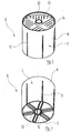
- FIGS. 2 and 3 which this dryer cartridge 6 in two different Show perspective views.
- the dryer cartridge 6 comprises an open top Pot-like cartridge housing 7 with one after Above conically widening peripheral wall 8 and one piece molded bottom 9. Through the interior of the Cartridge housing 7 extends from the bottom 9 which it is molded in one piece, an upward tapered tube 10. The tube 10 is down open; in its upper end area is the lower end area of the riser 5 inserted.
- the peripheral wall 8 of the cartridge housing 7 is from passes through several axially parallel slots 11, which do not quite reach the upper edge of the peripheral wall 8, down to the bottom 9, however are.
- Slots 12 extend through the wall in a similar manner of tube 10, which is not completely to the top of the tube 10, on the other hand completely up to the lower End out.
- the interior of the pot-shaped cartridge housing 7 is with a bed of desiccant, for example Molecular sieve filled to the top.
- a ring-shaped Lid 13 is in the cartridge housing 7 from above introduced and locked on the peripheral wall 8. How in particular Figure 2 shows runs through the lid 13 a plurality of narrow slots with a width of, for example, 0.5 mm.
- the slot width is like this chosen that the grains of desiccant, which are located in the dryer cartridge 6, the slots 14 can't happen.
- the shape of the slots 14 prevented at the same time that these are completely grains of the desiccant can clog.
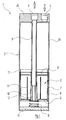
- the housing 2 of the collector dryer 1 is down through closed a metallic bottom 15, which on the Cylinder wall 2a of the housing 2 is either permanently welded on or screwed detachably to this cylinder wall 2a can be.
- the refrigerant which is predominantly in the liquid Phase and only to a minor extent in the gaseous phase Phase is present, occurs through the inlet bore 4 in the Interior of the housing 2 a.
- the top of this Interior which is penetrated by the riser 5, serves as a collector space for the gaseous phase of the refrigerant, how this is known in and of itself.
- the liquid Refrigerant sinks down inside the housing 2 and passes through the slots 14 in the lid 13 of the Dryer cartridge 6. This way it gets to the desiccant contained in the dryer cartridge 6, that removes moisture from the refrigerant.
- Figure 4 shows in axial section one on the same construction principle based refrigerant dryer. Parts that correspond to those of the collector dryer described above, are identified by the same reference number plus 100.
- the refrigerant dryer 101 in FIG. 4 does not contain any Refrigerant gaseous phase collector space; its housing 102 is therefore very much in the axial direction shorter than the housing 2 of the collector dryer from FIG. 1.
- FIGS. 1 to 3 both the inlet bore 3 and the outlet bore 4
- the refrigerant dryer is located in the upper housing cover 2b 101 of Figure 4 from a central inlet bore 104 in the floor 115 to a central outlet bore 103 flows in the cover 102b of the housing 102.
- the Construction largely of the dryer cartridge 6 of the figures 1 to 3 corresponds, but in the opposite direction is installed. That is, the cover 113 of the dryer cartridge 106 lies below while the bottom 109 of the dryer cartridge 106 located above.
- Another difference the dryer cartridge 106 compared to the dryer cartridge 6 of Figures 1 to 3 is that by the Inside the dryer cartridge 106 guided pipe 110 closed its end facing the inlet opening 104 is.
- the direct coaxial flow into tube 110 is not possible, since this tube 110, as already mentioned, at this end is closed. Instead, the refrigerant is forced through the different in the section of Figure 4 not recognizable (see, however, the slots 14 in FIG. 2) Slots in the cover 113 of the refrigerant cartridge 106 to flow, causing it to be inside the dryer cartridge 106 desiccant located.
- the housing 202 of the collector dryer 201 has a very narrow and tall shape.
- This collector dryer 201 is used wherever the installation conditions a corresponding one in the engine compartment of a motor vehicle Demand geometry.
- the housing 202 is naturally open at the top and by a cover 202b inserted afterwards locked.
- the bottom 215 of the housing 202 is against it integrally formed on the cylinder wall 202a.
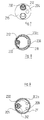
- a dryer cartridge is located in the interior of the housing 202 206, drawn out in perspective in FIG. 10 is.
- the dryer cartridge 206 includes a housing 207, whose peripheral wall 208 as opposed to the cylinder wall 202a of the housing 202 understood "tilted" cone can be.
- the peripheral wall 208 runs along one Surface line, which is shown on the left in Figure 5, axially parallel and here lies on the peripheral wall 202a of the Housing 202 on.
- the peripheral wall 208 of the cartridge housing 207 is in turn penetrated by a plurality of slots 211. These slots can have a slightly larger width than the slots 212 in the region of the tube section 230.
- the escape of particle fragments or other small solid bodies from the interior of the cartridge housing 207 is again prevented by a fine-mesh sieve (mesh size approximately 21 ⁇ m), which is not shown, and which is placed over the peripheral wall 208.
- the interior of the cartridge case 207 with the exception of the pipe section 230 is, as already mentioned, with desiccant filled.
- a lid 213, however, in this Embodiment has no openings is from into the peripheral wall 208 of the cartridge housing 207 introduced and locked there.
- a compression spring 216 clamped, which the entire dryer cartridge 206 after pushes down so that a step 231 in the lower area of the riser 205 at the upper end of the floor 215 triggers.
- Refrigerant present in the gaseous phase passes over the inlet bore 204 into the collector dryer 201, flows through the riser 205 upwards and flows into the pipe section 230 of the cartridge housing 207.
- the refrigerant arrives in the radial direction into the desiccant, which is the outside of the Pipe section 230 lying interior of the cartridge housing 207 occupies.
- This desiccant is used in flows essentially in the radial direction.
- the refrigerant then passes through the slits 211 in the peripheral wall 208 of the cartridge housing 207 and then flows in the axial direction downwards within the housing 202 to the outlet bore 203, over which it is dried, leaves the collector dryer 201.
- Embodiments also reverse the Flow direction possible. But then it must be Make sure that the refrigerant when A fine-mesh sieve emerges from the desiccant penetrates to wash out particle particles to prevent the header dryer or refrigerant dryer.
Applications Claiming Priority (2)
| Application Number | Priority Date | Filing Date | Title |
|---|---|---|---|
| DE2002103481 DE10203481A1 (de) | 2002-01-30 | 2002-01-30 | Kältemitteltrockner für Klima- oder Kälteanlagen, insbesondere für Fahrzeug-Klimaanlagen |
| DE10203481 | 2002-01-30 |
Publications (2)
| Publication Number | Publication Date |
|---|---|
| EP1333235A2 true EP1333235A2 (fr) | 2003-08-06 |
| EP1333235A3 EP1333235A3 (fr) | 2003-10-08 |
Family
ID=7713346
Family Applications (1)
| Application Number | Title | Priority Date | Filing Date |
|---|---|---|---|
| EP02026724A Withdrawn EP1333235A3 (fr) | 2002-01-30 | 2002-11-30 | Sécheur réfrigerant pour système de climatisation en particulier pour des systèmes de climatisation de véhicules |
Country Status (2)
| Country | Link |
|---|---|
| EP (1) | EP1333235A3 (fr) |
| DE (1) | DE10203481A1 (fr) |
Cited By (1)
| Publication number | Priority date | Publication date | Assignee | Title |
|---|---|---|---|---|
| FR2900466A1 (fr) * | 2006-04-28 | 2007-11-02 | Valeo Systemes Thermiques | Reservoir ameliore pour echangeur de chaleur et echangeur de chaleur correspondant |
Citations (1)
| Publication number | Priority date | Publication date | Assignee | Title |
|---|---|---|---|---|
| DE19545791C2 (de) | 1995-12-08 | 1998-02-05 | Hansa Metallwerke Ag | Filtertrockner, insbesondere Groß-Filtertrockner, für stationäre Kälteanlagen, sowie Filtertrocknerkartusche zur Verwendung bei einem solchen Filtertrockner |
Family Cites Families (6)
| Publication number | Priority date | Publication date | Assignee | Title |
|---|---|---|---|---|
| US5685087A (en) * | 1995-09-08 | 1997-11-11 | Stanhope Products Company | Fluid flow adsorbent container |
| DE19533666A1 (de) * | 1995-09-12 | 1997-03-13 | Hansa Metallwerke Ag | Akkumulator für eine nach dem "Orifice"-Prinzip arbeitende Klimaanlage, insbesondere Fahrzeugklimaanlage |
| FR2750761B1 (fr) * | 1996-07-03 | 1998-10-09 | Valeo Thermique Moteur Sa | Condenseur a filtre pour installation de climatisation de vehicule automobile |
| US5813245A (en) * | 1996-10-25 | 1998-09-29 | White Consolidated Industries, Inc. | Pressure relief circuit for refrigerator contained water filter |
| FR2770896B1 (fr) * | 1997-11-10 | 2000-01-28 | Valeo Thermique Moteur Sa | Condenseur de climatisation muni d'un reservoir de fluide a cartouche interchangeable |
| DE19905378C1 (de) * | 1999-02-10 | 2000-08-03 | Hansa Metallwerke Ag | Filtertrockner, insbesondere Groß-Filtertrockner, für stationäre Kälteanlagen sowie Filtertrocknerkartusche zur Verwendung bei einem solchen Filtertrockner |
-
2002
- 2002-01-30 DE DE2002103481 patent/DE10203481A1/de not_active Ceased
- 2002-11-30 EP EP02026724A patent/EP1333235A3/fr not_active Withdrawn
Patent Citations (1)
| Publication number | Priority date | Publication date | Assignee | Title |
|---|---|---|---|---|
| DE19545791C2 (de) | 1995-12-08 | 1998-02-05 | Hansa Metallwerke Ag | Filtertrockner, insbesondere Groß-Filtertrockner, für stationäre Kälteanlagen, sowie Filtertrocknerkartusche zur Verwendung bei einem solchen Filtertrockner |
Cited By (1)
| Publication number | Priority date | Publication date | Assignee | Title |
|---|---|---|---|---|
| FR2900466A1 (fr) * | 2006-04-28 | 2007-11-02 | Valeo Systemes Thermiques | Reservoir ameliore pour echangeur de chaleur et echangeur de chaleur correspondant |
Also Published As
| Publication number | Publication date |
|---|---|
| EP1333235A3 (fr) | 2003-10-08 |
| DE10203481A1 (de) | 2003-08-14 |
Similar Documents
| Publication | Publication Date | Title |
|---|---|---|
| EP0669506B1 (fr) | Condenseur pour une installation de climatisation d'un véhicule | |
| EP2129978B1 (fr) | Condenseur destiné à une climatisation, notamment à une climatisation de véhicule | |
| DE1761600B2 (de) | Vorrichtung zum sichten von faserstoffaufschwemmungen | |
| WO2007073783A1 (fr) | Systeme d'epuration de gaz | |
| DE102007048321A1 (de) | Vorrichtung und Verfahren zum Abscheiden einer Flüssigkeit aus einem Gasstrom sowie Brennstoffzellensystem | |
| DE19545791C2 (de) | Filtertrockner, insbesondere Groß-Filtertrockner, für stationäre Kälteanlagen, sowie Filtertrocknerkartusche zur Verwendung bei einem solchen Filtertrockner | |
| DE102005024158C5 (de) | Trockner für ein Kühlmedium in einem Kühlmedienkreislauf, insbesondere für eine Klimaanlage eines Fahrzeugs | |
| EP1333235A2 (fr) | Sécheur réfrigerant pour système de climatisation en particulier pour des systèmes de climatisation de véhicules | |
| DE3319909A1 (de) | Vorrichtung zum auswaschen von farbnebel aus der abluft von lackieranlagen | |
| EP1623167A1 (fr) | Dispositif pour condenser un agent de refroidissement | |
| DE10300801B3 (de) | Akkumulator für eine Klimaanlage, insbesondere Fahrzeugklimaanlage | |
| DE102005024167B4 (de) | Trockner für ein Kühlmedium in einem Kühlmedienkreislauf, insbesondere für eine Klimaanlage eines Fahrzeugs | |
| EP1361401B1 (fr) | Cartouche de filtrage et séchage | |
| DE19706620B4 (de) | Abtrenneinrichtung für Regenwasser | |
| DE102007028591A1 (de) | Akkumulator, insbesondere für eine Kraftfahrzeug- Klimaanlage | |
| DE19905354C2 (de) | Kältekreislauf mit Verflüssiger, Verdampfer und integriertem Trockenmittel | |
| EP3743190B1 (fr) | Élément filtrant, en particulier pour la filtration de gaz | |
| DE102004032279B3 (de) | Akkumulator für eine Klimaanlage, insbesondere Fahrzeug-Klimaanlage | |
| EP1316765B1 (fr) | Accumulateur pour système de climatisation, en particulier pour des systèmes de climatisation de véhicule | |
| DE10300802A1 (de) | Akkumulator für eine Klimaanlage, insbesondere für Fahrzeugklimaanlage | |
| WO2006102862A1 (fr) | Ensemble deshydrateur installe dans un circuit de refrigerant | |
| DE10237179A1 (de) | Akkumulator für eine nach dem Orifice-Prinzip arbeitende Klimaanlage, insbesondere Fahrzeugklimaanlage | |
| DE20317084U1 (de) | Sieb aus gesintertem Werkstoff für einen Kältekreislauf mit Verflüssiger, Verdampfer und integriertem Trockenmittel | |
| DE202019105321U1 (de) | Zyklonabscheider und Filter mit einem Zyklonabscheider | |
| DE3923735C1 (fr) |
Legal Events
| Date | Code | Title | Description |
|---|---|---|---|
| PUAI | Public reference made under article 153(3) epc to a published international application that has entered the european phase |
Free format text: ORIGINAL CODE: 0009012 |
|
| AK | Designated contracting states |
Designated state(s): AT BE BG CH CY CZ DE DK EE ES FI FR GB GR IE IT LI LU MC NL PT SE SK TR |
|
| AX | Request for extension of the european patent |
Extension state: AL LT LV MK RO SI |
|
| PUAL | Search report despatched |
Free format text: ORIGINAL CODE: 0009013 |
|
| AK | Designated contracting states |
Kind code of ref document: A3 Designated state(s): AT BE BG CH CY CZ DE DK EE ES FI FR GB GR IE IT LI LU MC NL PT SE SK TR |
|
| AX | Request for extension of the european patent |
Extension state: AL LT LV MK RO SI |
|
| AKX | Designation fees paid | ||
| REG | Reference to a national code |
Ref country code: DE Ref legal event code: 8566 |
|
| STAA | Information on the status of an ep patent application or granted ep patent |
Free format text: STATUS: THE APPLICATION IS DEEMED TO BE WITHDRAWN |
|
| 18D | Application deemed to be withdrawn |
Effective date: 20040409 |