EP1333235A2 - Refrigerant dryer for air conditioners especially for vehicle air conditioners - Google Patents
Refrigerant dryer for air conditioners especially for vehicle air conditioners Download PDFInfo
- Publication number
- EP1333235A2 EP1333235A2 EP02026724A EP02026724A EP1333235A2 EP 1333235 A2 EP1333235 A2 EP 1333235A2 EP 02026724 A EP02026724 A EP 02026724A EP 02026724 A EP02026724 A EP 02026724A EP 1333235 A2 EP1333235 A2 EP 1333235A2
- Authority
- EP
- European Patent Office
- Prior art keywords
- refrigerant
- housing
- cartridge
- dryer
- cartridge housing
- Prior art date
- Legal status (The legal status is an assumption and is not a legal conclusion. Google has not performed a legal analysis and makes no representation as to the accuracy of the status listed.)
- Withdrawn
Links
Images


Classifications
-
- F—MECHANICAL ENGINEERING; LIGHTING; HEATING; WEAPONS; BLASTING
- F25—REFRIGERATION OR COOLING; COMBINED HEATING AND REFRIGERATION SYSTEMS; HEAT PUMP SYSTEMS; MANUFACTURE OR STORAGE OF ICE; LIQUEFACTION SOLIDIFICATION OF GASES
- F25B—REFRIGERATION MACHINES, PLANTS OR SYSTEMS; COMBINED HEATING AND REFRIGERATION SYSTEMS; HEAT PUMP SYSTEMS
- F25B43/00—Arrangements for separating or purifying gases or liquids; Arrangements for vaporising the residuum of liquid refrigerant, e.g. by heat
- F25B43/003—Filters
Definitions
- Refrigerant dryers do the job in one Air conditioning or refrigeration system circulating refrigerant To remove moisture.
- filter dryers especially in the form of collector dryers, and accumulators.
- Filter dryers are in the refrigerant circuit immediately downstream of the condenser and are essentially liquid refrigerant flows through.
- the accumulators used in Air conditioning or refrigerant systems working according to the "orifice" principle be used there immediately behind arranged the evaporator and essentially of gaseous Refrigerant flows through.
- a hollow cartridge housing which is generally cylindrical, there is a bed of desiccant, in general a molecular sieve, in the form of more or less regularly shaped balls or grains.
- a refrigerant dryer of the type mentioned at the beginning, in the form of a filter dryer, is in DE 199 05 368 C1.
- the tools for making Such windows are required are comparative complicated.
- This type of refrigerant dryer also includes the desiccant grains directly to the Seven and can, especially in the case of vibrations, mechanically damage these screens.
- the object of the present invention is a refrigerant dryer of the type mentioned at the outset, that its manufacture simple and the throttling of the refrigerant flow is low.
- This object is achieved in that at least one opening of the cartridge housing as an elongated Slit is formed, the width of which is smaller than the diameter of the desiccant particles.
- a slot can be so narrow be chosen so that its narrow width already prevents that desiccant particles escape. Still can over the length of the slot is such a large passage area for the refrigerant that are throttled is low.
- the slot shape also prevents the entire opening through individual, sitting desiccant particles can close what is also in low throttling of the refrigerant flow.
- those used according to the invention Slits are also cheaper from a manufacturing point of view, since they also have to produce simpler slides of the mold are.
- the slots are expediently on the inlet side of the cartridge housing is narrower than the slots the outside of the cartridge housing.
- the inlet side In this way, slots can replace sieves that in known refrigerant dryers as the inlet side Particle sieves are used.
- These slots on the inlet side of the cartridge case should be 0.5mm or less in width.
- the slots are expediently on the outside of the cartridge housing through a fine-mesh sieve covered.
- This fine-meshed sieve has, however, different than in the prior art, not the function that Desiccant particles inside the cartridge housing to keep; this function is already from the slots taken over myself.
- the fine-meshed sieve serves rather exclusively as a fine particle sieve, which helps flushing out of fine particles, for example Fragments of desiccant particles in the downstream Refrigerant system prevented.
- the mesh size of this additional sieve should be up to be about 20 ⁇ m.
- the screen on the outside of the cartridge housing is arranged.
- the sieve with the desiccant particles does not come in contact, as this through the slots in the cartridge housing held on the inside of the cartridge housing become. Mechanical damage to the sieve abrupt desiccant particles that move when shaken can therefore not take place.
- the outer surface of the cartridge housing is conical. In this case making the slots in the cartridge housing further simplified since the corresponding slider after the spraying process slightly withdrawn in the axial direction can be and already after a proportionate short movement distance from the manufactured workpiece come free.
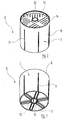
- FIGS. 2 and 3 which this dryer cartridge 6 in two different Show perspective views.
- the dryer cartridge 6 comprises an open top Pot-like cartridge housing 7 with one after Above conically widening peripheral wall 8 and one piece molded bottom 9. Through the interior of the Cartridge housing 7 extends from the bottom 9 which it is molded in one piece, an upward tapered tube 10. The tube 10 is down open; in its upper end area is the lower end area of the riser 5 inserted.
- the peripheral wall 8 of the cartridge housing 7 is from passes through several axially parallel slots 11, which do not quite reach the upper edge of the peripheral wall 8, down to the bottom 9, however are.
- Slots 12 extend through the wall in a similar manner of tube 10, which is not completely to the top of the tube 10, on the other hand completely up to the lower End out.
- the interior of the pot-shaped cartridge housing 7 is with a bed of desiccant, for example Molecular sieve filled to the top.
- a ring-shaped Lid 13 is in the cartridge housing 7 from above introduced and locked on the peripheral wall 8. How in particular Figure 2 shows runs through the lid 13 a plurality of narrow slots with a width of, for example, 0.5 mm.
- the slot width is like this chosen that the grains of desiccant, which are located in the dryer cartridge 6, the slots 14 can't happen.
- the shape of the slots 14 prevented at the same time that these are completely grains of the desiccant can clog.
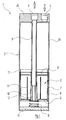
- the housing 2 of the collector dryer 1 is down through closed a metallic bottom 15, which on the Cylinder wall 2a of the housing 2 is either permanently welded on or screwed detachably to this cylinder wall 2a can be.
- the refrigerant which is predominantly in the liquid Phase and only to a minor extent in the gaseous phase Phase is present, occurs through the inlet bore 4 in the Interior of the housing 2 a.
- the top of this Interior which is penetrated by the riser 5, serves as a collector space for the gaseous phase of the refrigerant, how this is known in and of itself.
- the liquid Refrigerant sinks down inside the housing 2 and passes through the slots 14 in the lid 13 of the Dryer cartridge 6. This way it gets to the desiccant contained in the dryer cartridge 6, that removes moisture from the refrigerant.
- Figure 4 shows in axial section one on the same construction principle based refrigerant dryer. Parts that correspond to those of the collector dryer described above, are identified by the same reference number plus 100.
- the refrigerant dryer 101 in FIG. 4 does not contain any Refrigerant gaseous phase collector space; its housing 102 is therefore very much in the axial direction shorter than the housing 2 of the collector dryer from FIG. 1.
- FIGS. 1 to 3 both the inlet bore 3 and the outlet bore 4
- the refrigerant dryer is located in the upper housing cover 2b 101 of Figure 4 from a central inlet bore 104 in the floor 115 to a central outlet bore 103 flows in the cover 102b of the housing 102.
- the Construction largely of the dryer cartridge 6 of the figures 1 to 3 corresponds, but in the opposite direction is installed. That is, the cover 113 of the dryer cartridge 106 lies below while the bottom 109 of the dryer cartridge 106 located above.
- Another difference the dryer cartridge 106 compared to the dryer cartridge 6 of Figures 1 to 3 is that by the Inside the dryer cartridge 106 guided pipe 110 closed its end facing the inlet opening 104 is.
- the direct coaxial flow into tube 110 is not possible, since this tube 110, as already mentioned, at this end is closed. Instead, the refrigerant is forced through the different in the section of Figure 4 not recognizable (see, however, the slots 14 in FIG. 2) Slots in the cover 113 of the refrigerant cartridge 106 to flow, causing it to be inside the dryer cartridge 106 desiccant located.
- the housing 202 of the collector dryer 201 has a very narrow and tall shape.
- This collector dryer 201 is used wherever the installation conditions a corresponding one in the engine compartment of a motor vehicle Demand geometry.
- the housing 202 is naturally open at the top and by a cover 202b inserted afterwards locked.
- the bottom 215 of the housing 202 is against it integrally formed on the cylinder wall 202a.
- a dryer cartridge is located in the interior of the housing 202 206, drawn out in perspective in FIG. 10 is.
- the dryer cartridge 206 includes a housing 207, whose peripheral wall 208 as opposed to the cylinder wall 202a of the housing 202 understood "tilted" cone can be.
- the peripheral wall 208 runs along one Surface line, which is shown on the left in Figure 5, axially parallel and here lies on the peripheral wall 202a of the Housing 202 on.
- the peripheral wall 208 of the cartridge housing 207 is in turn penetrated by a plurality of slots 211. These slots can have a slightly larger width than the slots 212 in the region of the tube section 230.
- the escape of particle fragments or other small solid bodies from the interior of the cartridge housing 207 is again prevented by a fine-mesh sieve (mesh size approximately 21 ⁇ m), which is not shown, and which is placed over the peripheral wall 208.
- the interior of the cartridge case 207 with the exception of the pipe section 230 is, as already mentioned, with desiccant filled.
- a lid 213, however, in this Embodiment has no openings is from into the peripheral wall 208 of the cartridge housing 207 introduced and locked there.
- a compression spring 216 clamped, which the entire dryer cartridge 206 after pushes down so that a step 231 in the lower area of the riser 205 at the upper end of the floor 215 triggers.
- Refrigerant present in the gaseous phase passes over the inlet bore 204 into the collector dryer 201, flows through the riser 205 upwards and flows into the pipe section 230 of the cartridge housing 207.
- the refrigerant arrives in the radial direction into the desiccant, which is the outside of the Pipe section 230 lying interior of the cartridge housing 207 occupies.
- This desiccant is used in flows essentially in the radial direction.
- the refrigerant then passes through the slits 211 in the peripheral wall 208 of the cartridge housing 207 and then flows in the axial direction downwards within the housing 202 to the outlet bore 203, over which it is dried, leaves the collector dryer 201.
- Embodiments also reverse the Flow direction possible. But then it must be Make sure that the refrigerant when A fine-mesh sieve emerges from the desiccant penetrates to wash out particle particles to prevent the header dryer or refrigerant dryer.
Abstract
Description
Die Erfindung betrifft einen Kältemitteltrockner für
Klima- oder Kälteanlagen, insbesondere für Fahrzeug-Klimaanlagen,
mit
Kältemitteltrockner haben die Aufgabe, dem in einer Klima- oder Kälteanlage zirkulierenden Kältemittel die Feuchtigkeit zu entziehen. Je nach Anbringungsort des Kältemitteltrockners unterscheidet man zwischen Filtertrocknern, insbesondere in der Form von Sammlertrocknern, und Akkumulatoren. Filtertrockner befinden sich im Kältemittelkreislauf unmittelbar stromab vom Verflüssiger und werden im wesentlichen von flüssigem Kältemittel durchströmt. Anders dagegen die Akkumulatoren, die bei nach dem "Orifice"-Prinzip arbeitenden Klima- oder Kältemittelanlagen eingesetzt werden, dort unmittelbar hinter dem Verdampfer angeordnet und im wesentlich von gasförmigem Kältemittel durchströmt werden. An der grundsätzlichen Bauweise der in diesen unterschiedlichen Arten von Kältemitteltrocknern eingesetzten Trocknerkartusche ändert dies jedoch nichts: In einem hohlen Kartuschengehäuse, das im allgemeinen zylindrisch ausgebildet ist, befindet sich die Schüttung eines Trockenmittels, im allgemeinen eines Molekularsiebes, in Form von mehr oder weniger regelmäßig geformten Kugeln oder Körnern.Refrigerant dryers do the job in one Air conditioning or refrigeration system circulating refrigerant To remove moisture. Depending on the location of the Refrigerant dryers are differentiated between filter dryers, especially in the form of collector dryers, and accumulators. Filter dryers are in the refrigerant circuit immediately downstream of the condenser and are essentially liquid refrigerant flows through. In contrast, the accumulators used in Air conditioning or refrigerant systems working according to the "orifice" principle be used there immediately behind arranged the evaporator and essentially of gaseous Refrigerant flows through. At the basic Construction of the in these different types dryer cartridge used by refrigerant dryers However, this does not change anything: in a hollow cartridge housing, which is generally cylindrical, there is a bed of desiccant, in general a molecular sieve, in the form of more or less regularly shaped balls or grains.
Ein Kältemitteltrockner der eingangs genannten Art, und zwar in Form eines Filtertrockners, ist in der DE 199 05 368 C1 beschrieben. Hier besitzen die Öffnungen, über welche das Kältemittel in die Trocknerkartusche hinein und aus dieser wieder herausströmt, die Form von verhältnismaßig großen Fenstern, die jeweils durch Siebe abgedeckt sind. Die Werkzeuge, die zur Herstellung derartiger Fenster erforderlich sind, sind vergleichsweise kompliziert. Außerdem liegen bei dieser Art von Kältemitteltrockner die Körner des Trockenmittels direkt an den Sieben an und können, insbesondere bei Erschütterungen, diese Siebe mechanisch beschädigen.A refrigerant dryer of the type mentioned at the beginning, in the form of a filter dryer, is in DE 199 05 368 C1. Here are the openings through which the refrigerant enters the dryer cartridge flows in and out of it, the form of relatively large windows, each through Strainers are covered. The tools for making Such windows are required are comparative complicated. This type of refrigerant dryer also includes the desiccant grains directly to the Seven and can, especially in the case of vibrations, mechanically damage these screens.
Bei einem weiteren Filtertrockner, der ebenfalls der eingangs genannten Art entspricht und in der DE 195 45 791 C2 beschrieben ist, ist in den Stirnseiten des Kartuschengehäuses eine Vielzahl von kreisförmigen Öffnungen vorgesehen, über welche das Kältemittel zu- bzw. abströmen kann. Sofern diese Öffnungen klein genug sind, um alleine den Austritt von Partikeln des Trockenmittels zu verhindern, besteht hier die Gefahr, daß sich die Öffnungen durch ein einsitzendes Partikel zusetzen, was zu einer hohen Drosselung des Kältemittelstroms führen würde. Zusätzlich sind auch diese kreisförmigen Öffnungen verhältnismäßig schwer herzustellen.In another filter dryer, which is also the corresponds to the type mentioned at the beginning and in DE 195 45 791 C2 is described in the front of the Cartridge housing a variety of circular openings provided, through which the refrigerant is supplied or can flow off. If these openings are small enough to prevent the desiccant from leaking to prevent, there is a risk that the Clogged openings by a sitting particle what lead to high throttling of the refrigerant flow would. In addition, these are circular openings relatively difficult to manufacture.
Aufgabe der vorliegenden Erfindung ist es, einen Kältemitteltrockner der eingangs genannten Art so auszugestalten, daß seine Herstellung einfach und die Drosselung des Kältemittelstromes gering ist.The object of the present invention is a refrigerant dryer of the type mentioned at the outset, that its manufacture simple and the throttling of the refrigerant flow is low.
Diese Aufgabe wird erfindungsgemäß dadurch gelöst, daß mindestens eine Öffnung des Kartuschengehäuses als langgestreckter Schlitz ausgebildet ist, dessen Breite kleiner als der Durchmesser der Trockenmittelpartikel ist.This object is achieved in that at least one opening of the cartridge housing as an elongated Slit is formed, the width of which is smaller than the diameter of the desiccant particles.
Die erfindungsgemäß gewählte Form des Schlitzes für die Öffnungen des Kartuschengehäuses bringt mehrere Vorteile mit sich: Ein Schlitz kann einerseits so schmal gewählt werden, daß bereits seine geringe Breite verhindert, daß Trockenmittelpartikel austreten. Trotzdem kann über die Länge des Schlitzes eine so große Durchtrittsfläche für das Kältemittel gewonnen werden, daß die Drosselung gering ist. Die Schlitzform verhindert außerdem, daß sich die gesamte Öffnung durch einzelne, einsitzende Trockenmittelpartikel verschließen kann, was sich ebenfalls in einer geringen Drosselung des Kältemittelstromes niederschlägt. Schließlich sind die erfindungsgemäß eingesetzten Schlitze auch herstellungstechnisch günstiger, da sie mit einfacheren Schiebern des Formwerkzeuges herzustellen sind.The shape of the slot chosen according to the invention for the openings of the cartridge housing brings several Advantages with it: On the one hand, a slot can be so narrow be chosen so that its narrow width already prevents that desiccant particles escape. Still can over the length of the slot is such a large passage area for the refrigerant that are throttled is low. The slot shape also prevents the entire opening through individual, sitting desiccant particles can close what is also in low throttling of the refrigerant flow. Finally, those used according to the invention Slits are also cheaper from a manufacturing point of view, since they also have to produce simpler slides of the mold are.
Zweckmäßigerweise sind die Schlitze auf der Einlaßseite des Kartuschengehäuses schmäler als die Schlitze auf der Außenseite des Kartuschengehäuses. Die einlaßseitigen Schlitze können auf diese Weise Siebe ersetzen, die bei bekannten Kältemitteltrocknern als einlaßseitige Partikelsiebe eingesetzt werden.The slots are expediently on the inlet side of the cartridge housing is narrower than the slots the outside of the cartridge housing. The inlet side In this way, slots can replace sieves that in known refrigerant dryers as the inlet side Particle sieves are used.
Diese Schlitze auf der Einlaßseite des Kartuschengehäuses sollten eine Breite von 0,5 mm oder weniger besitzen.These slots on the inlet side of the cartridge case should be 0.5mm or less in width.
Zweckmäßigerweise sind die Schlitze auf der Außenseite des Kartuschengehäuses durch ein feinmaschiges Sieb abgedeckt. Dieses feinmaschige Sieb hat aber, anders als beim Stand der Technik, nicht die Funktion, die Trockenmittelpartikel im Inneren des Kartuschengehäuses zu halten; diese Funktion wird schon von den Schlitzen selbst übernommen. Das feinmaschige Sieb dient vielmehr ausschließlich als Feinteilchensieb, welches das Ausschwemmen von feinen Partikeln, also beispielsweise Bruchstücken von Trockenmittelpartikeln, in das nachgeschaltete Kältemittelsystem verhindert.The slots are expediently on the outside of the cartridge housing through a fine-mesh sieve covered. This fine-meshed sieve has, however, different than in the prior art, not the function that Desiccant particles inside the cartridge housing to keep; this function is already from the slots taken over myself. The fine-meshed sieve serves rather exclusively as a fine particle sieve, which helps flushing out of fine particles, for example Fragments of desiccant particles in the downstream Refrigerant system prevented.
Die Maschenweite dieses zusätzlichen Siebs sollte bis zu etwa 20 µm betragen.The mesh size of this additional sieve should be up to be about 20 µm.
Besonders bevorzugt wird, wenn das Sieb auf der Außenseite des Kartuschengehäuses angeordnet ist. In diesem Fall kommt das Sieb mit den Trockenmittelpartikeln nicht in Berührung, da ja diese durch die Schlitze des Kartuschengehäuses auf der Innenseite des Kartuschengehäuses gehalten werden. Eine mechanische Beschädigung des Siebes durch anstoßende, sich bei Erschütterungen bewegende Trockenmittelpartikel kann somit nicht stattfinden.It is particularly preferred if the screen on the outside of the cartridge housing is arranged. In this case the sieve with the desiccant particles does not come in contact, as this through the slots in the cartridge housing held on the inside of the cartridge housing become. Mechanical damage to the sieve abrupt desiccant particles that move when shaken can therefore not take place.
Zweckmäßig ist ferner, wenn die Mantelfläche des Kartuschengehäuses konisch ausgebildet ist. In diesem Fall ist die Herstellung der Schlitze in dem Kartuschengehäuse weiter vereinfacht, da die entsprechenden Schieber nach dem Spritzvorgang leicht in axialer Richtung zurückgezogen werden können und bereits nach einer verhältnismäßig kurzen Bewegungsstrecke von dem hergestellten Werkstück freikommen.It is also expedient if the outer surface of the cartridge housing is conical. In this case making the slots in the cartridge housing further simplified since the corresponding slider after the spraying process slightly withdrawn in the axial direction can be and already after a proportionate short movement distance from the manufactured workpiece come free.
Ausführungsbeispiele der Erfindung werden nachfolgend anhand der Zeichnung näher erläutert; es zeigen
- Figur 1
- einen Axialschnitt durch einen Sammlertrockner;
Figur 2- eine perspektivische Ansicht der in dem Sammlertrockner von Figur 1 enthaltenen Trocknerkartusche, von oben gesehen;
Figur 3- eine perspektivische Ansicht der Trocknerkartusche
von
Figur 2, von unten gesehen; - Figur 4
- einen Axialschnitt durch einen Trockner, der ohne Sammelraum ausgeführt ist;
Figur 5- einen Axialschnitt durch ein zweites Ausführungsbeispiel eines Sammlertrockners;
Figur 6- einen Axialschnitt durch den Sammlertrockner
von
Figur 5 in einer zur Schnittebene vonFigur 5 senkrecht stehenden Schnittebene; Figur 7- die Unteransicht des Sammlertrockners der
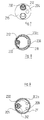
Figuren 5 und 6; Figur 8- einen Schnitt durch den Sammlertrockner der
Figuren 5 und 6 gemäß der Linie VIII-VIII vonFigur 5; Figur 9- einen Schnitt durch den Sammlertrockner der
Figuren 5 und 6 gemäß der Linie IX-IX vonFigur 5; Figur 10- eine perspektivische Ansicht der Trocknerkartusche
des in den
Figuren 5 bis 9 dargestellten Sammlertrockners.
- Figure 1
- an axial section through a collector dryer;
- Figure 2
- a perspective view of the dryer cartridge contained in the collector dryer of Figure 1, seen from above;
- Figure 3
- a perspective view of the dryer cartridge of Figure 2, seen from below;
- Figure 4
- an axial section through a dryer, which is carried out without a collecting space;
- Figure 5
- an axial section through a second embodiment of a collector dryer;
- Figure 6
- an axial section through the collector dryer of Figure 5 in a section plane perpendicular to the section plane of Figure 5;
- Figure 7
- the bottom view of the collector dryer of Figures 5 and 6;
- Figure 8
- a section through the collector dryer of Figures 5 and 6 along the line VIII-VIII of Figure 5;
- Figure 9
- a section through the collector dryer of Figures 5 and 6 along the line IX-IX of Figure 5;
- Figure 10
- a perspective view of the dryer cartridge of the collector dryer shown in Figures 5 to 9.
Der in Figur 1 im Axialschnitt dargestellte und insgesamt
mit dem Bezugszeichen 1 versehene Sammlertrockner umfaßt
ein metallisches Gehäuse 2, dessen durch eine Zylinderwand
2a gebildeter Mantel oben durch einen einstückig angeformten
Deckel 2b verschlossen ist. Koaxial zur Zylinderwand
2a verläuft durch den Deckel 2b des Gehäuses 2 eine
gestufte Auslaßbohrung 3; achsparallel hierzu, jedoch
außermittig, verläuft durch den Deckel 2b eine gestufte
Einlaßbohrung 4, die sich direkt in den Innenraum des
Gehäuses 2 öffnet.The one shown in Figure 1 in axial section and overall
Collector dryer provided with the reference number 1
a
In den inneren Endbereich der Auslaßbohrung 3 ist ein
Steigrohr 5 eingeschoben, das sich ebenfalls koaxial zur
Zylinderwand 2a des Gehäuses 2 nach unten erstreckt und
zu einer Trocknerkartusche führt, die insgesamt das
Bezugszeichen 6 trägt.In the inner end region of the outlet bore 3 is a
Bei der nachfolgenden Beschreibung der Trocknerkartusche
6 wird ergänzend auf die Figuren 2 und 3 Bezug genommen,
welche diese Trocknerkartusche 6 in zwei unterschiedlichen
perspektivischen Ansichten zeigen.In the following description of the
Die Trocknerkartusche 6 umfaßt ein nach oben offenes,
topfähnliches Kartuschengehäuse 7 mit einer sich nach
oben konisch erweiternden Umfangswand 8 und einem einstückig
angeformten Boden 9. Durch den Innenraum des
Kartuschengehäuses 7 erstreckt sich vom Boden 9, an
den es einstückig angeformt ist, ein sich nach oben
konisch verjüngendes Rohr 10. Das Rohr 10 ist nach unten
offen; in seinen oberen Endbereich ist der untere Endbereich
des Steigrohrs 5 eingeschoben. The
Die Umfangswand 8 des Kartuschengehäuses 7 wird von
mehreren achsparallelen Schlitzen 11 durchsetzt, welche
nicht ganz den oberen Rand der Umfangswand 8 erreichen,
nach unten jedoch bis durch den Boden 9 hindurch geführt
sind.The
In ähnlicher Weise verlaufen Schlitze 12 durch die Wandung
des Rohrs 10, die nicht vollständig bis zum oberen Ende
des Rohrs 10, dagegen vollständig bis zu dessen unterem
Ende geführt sind.
Über die konische Umfangswand 8 des Kartuschengehäuses
7 ist ein Sieb mit einer Maschenweite von bis zu etwa 20 µm
gelegt, das in der Zeichnung nicht dargestellt ist.Over the conical
Der Innenraum des topfförmigen Kartuschengehäuses 7
ist mit einer Schüttung aus Trockenmittel, beispielsweise
Molekularsieb, bis oben angefüllt. Ein ringförmiger
Deckel 13 ist von oben her in das Kartuschengehäuse 7
eingeführt und an der Umfangswand 8 verrastet. Wie insbesondere
die Figur 2 zeigt, verläuft durch den Deckel
13 eine Vielzahl von schmalen Schlitzen mit einer Breite
von beispielsweise 0,5 mm. Die Schlitzbreite ist so
gewählt, daß die Körner des Trockenmittels, welche sich
in der Trocknerkartusche 6 befinden, die Schlitze 14
nicht passieren können. Die Form der Schlitze 14 verhindert
gleichzeitig, daß diese sich vollständig mit Körnern
des Trockenmittels zusetzen können.The interior of the pot-shaped
Das Gehäuse 2 des Sammlertrockners 1 ist nach unten durch
einen metallischen Boden 15 verschlossen, der an der
Zylinderwand 2a des Gehäuses 2 entweder permanent angeschweißt
oder mit dieser Zylinderwand 2a lösbar verschraubt
sein kann. The
Zwischen der Innenseite des Bodens 15 des Gehäuses 2
und der Unterseite des Bodens 9 des Kartuschengehäuses 7
ist eine Druckfeder 16 verspannt. Diese drückt die gesamte
Trocknerkartusche 6 axial nach oben, bis der obere Rand
ihrer Umfangswand 8 an einer ringförmigen Sicke 17 anliegt,
die in der Zylinderwand 2a des Gehäuses 2 eingeformt
ist.Between the inside of the bottom 15 of the
Die Funktionsweise des beschriebenen Sammlertrockners 1 ist wie folgt:The mode of operation of the collector dryer 1 described is as follows:
Das Kältemittel, welches überwiegend in der flüssigen
Phase und nur zum kleineren Teil in der gasförmigen
Phase vorliegt, tritt über die Einlaßbohrung 4 in den
Innenraum des Gehäuses 2 ein. Der obere Bereich dieses
Innenraums, der von dem Steigrohr 5 durchstoßen wird,
dient als Sammlerraum für die gasförmige Phase des Kältemittels,
wie dies an und für sich bekannt ist. Das flüssige
Kältemittel sinkt im Innenraum des Gehäuses 2 nach unten
und durchtritt die Schlitze 14 in dem Deckel 13 der
Trocknerkartusche 6. Es gelangt auf diese Weise zu dem
in der Trocknerkartusche 6 enthaltenen Trockenmittel,
das dem Kältemittel die Feuchtigkeit entzieht. Statt
nun, wie dies beim Stand der Technik der Fall ist, das
gesamte Trockenmittel in axialer Richtung bis zum Boden
der Trocknerkartusche 6 zu durchströmen, ändert das Kältemittel
innerhalb des Trockenmittels seine Strömungsrichtung:
Zum einen biegt es in radialer Richtung nach außen um,
durchströmt die Schlitze 11 in der Umfangswand 8 des
Kartuschengehäuses 7 und fließt durch den sich konisch
erweiternden Spalt zwischen der Umfangswand 8 des Kartuschengehäuses
7 und der Zylinderwand 2a des Gehäuses 2
nach unten. The refrigerant, which is predominantly in the liquid
Phase and only to a minor extent in the gaseous phase
Phase is present, occurs through the inlet bore 4 in the
Interior of the housing 2 a. The top of this
Interior, which is penetrated by the
Ein anderer Teil des Kältemittels biegt innerhalb des
Trockenmittels in radialer Richtung nach innen um und
durchströmt die Schlitze 12 in der Wand des Rohrs 10.
Im Inneren des Rohres 10 trifft dieses Kältemittel auf
den anderen Kältemittelstrom, der die Schlitze 11 in der
Umfangswand 8 durchströmt hat. Der vereinigte Kältemittelstrom
fließt über das Steigrohr 5 zur Auslaßbohrung 3 und
verläßt auf diese Weise den Sammlertrockner 1.Another part of the refrigerant bends inside the
Desiccant in the radial direction around and
flows through the
Figur 4 zeigt im Axialschnitt einen auf dem selben Konstruktionsprinzip beruhenden Kältemitteltrockner. Teile, die solchen des oben beschriebenen Sammlertrockners entsprechen, sind mit dem selben Bezugszeichen zuzüglich 100 gekennzeichnet.Figure 4 shows in axial section one on the same construction principle based refrigerant dryer. Parts that correspond to those of the collector dryer described above, are identified by the same reference number plus 100.
Die Hauptunterschiede zwischen dem Kältemitteltrockner der Figur 4 und dem Sammlertrockner der Figuren 1 bis 3 bestehen in Folgendem:The main differences between the refrigerant dryer of Figure 4 and the collector dryer of Figures 1 to 3 consist of the following:
Der Kältemitteltrockner 101 der Figur 4 enthält keinen
Sammlerraum für die gasförmige Phase des Kältemittels;
sein Gehäuse 102 ist also in axialer Richtung sehr viel
kürzer als das Gehäuse 2 des Sammlertrockners von Figur 1.The
Während sich beim Sammlertrockner der Figuren 1 bis 3
sowohl die Einlaßbohrung 3 als auch die Auslaßbohrung 4
im oberen Gehäusedeckel 2b befanden, wird der Kältemitteltrockner
101 der Figur 4 von einer mittigen Einlaßbohrung
104 im Boden 115 zu einer mittigen Auslaßbohrung 103
im Deckel 102b des Gehäuses 102 durchströmt.While the collector dryer in FIGS. 1 to 3
both the inlet bore 3 and the outlet bore 4
The refrigerant dryer is located in the
Im Innenraum des Gehäuses 102 des Kältemitteltrockners
101 ist eine Trocknerkartusche 106 untergebracht, deren
Bauweise weitestgehend der Trocknerkartusche 6 der Figuren
1 bis 3 entspricht, die jedoch in umgekehrter Richtung
eingebaut ist. D. h., der Deckel 113 der Trocknerkartusche
106 liegt unten während sich der Boden 109 der Trocknerkartusche
106 oben befindet. Ein weiterer Unterschied
der Trocknerkartusche 106 gegenüber der Trocknerkartusche
6 der Figuren 1 bis 3 besteht darin, daß das durch das
Innere der Trocknerkartusche 106 geführte Rohr 110 an
seinem der Einläßöffnung 104 zugewandten Ende verschlossen
ist.In the interior of the
Die Funktionsweise des in Figur 4 dargestellten Kältemitteltrockners ist wie folgt:The operation of the refrigerant dryer shown in Figure 4 is as follows:
Das im wesentlichen aus der flüssigen Phase bestehende
Kältemittel strömt über der Einlaßöffnung 104 im Boden
115 in den Innenraum des Gehäuses 102 ein. Die direkte,
koaxiale Weiterströmung in das Rohr 110 ist nicht möglich,
da dieses Rohr 110, wie schon erwähnt, an diesem Ende
verschlossen ist. Stattdessen ist das Kältemittel gezwungen,
durch die verschiedenen im Schnitt von Figur 4 nicht
erkennbaren (vgl. jedoch die Schlitze 14 in Figur 2)
Schlitze im Deckel 113 der Kältemittelkartusche 106
zu fließen, wodurch es zu dem im Innenraum der Trocknerkartusche
106 befindlichen Trockenmittel gelangt. Erneut
findet eine Aufteilung der Kältemittelströmung statt: Ein
Teil des Kältemittels biegt radial nach außen um, durchfließt
die Schlitze 111 in der Umfangswand 108 des Kartuschengehäuses
107 und durch den ringförmigen Spalt zwischen
der Umfangswand 108 des Kartuschengehäuses 106 und der
Zylinderwand 102a des Gehäuses 102 nach oben. Ein weiterer
Teil des Kältemittels biegt im Trockenmittel radial nach
innen um, durchströmt die Schlitze 112 in dem Rohr 110 und
fließt im Rohr 110 in axialer Richtung nach oben. In
dem oberhalb des Bodens 109 der Trocknerkartusche 106
befindlichen Raum vereinigen sich die beiden Kältemittelströme
wieder und verlassen gemeinsam den Kältemitteltrockner
101 nach oben durch die Auslaßbohrung 103.That essentially consists of the liquid phase
Refrigerant flows through the inlet opening 104 in the
Obwohl die optische Ähnlichkeit auf den ersten Blick nicht zu groß ist, ist auch der in den Figuren 5 bis 10 dargestellte Sammlertrockner nach den selben grundlegenden Konstruktionsprinzipien gebaut wie der Sammlertrockner der Figuren 1 bis 3. Entsprechende Teile sind daher mit dem selben Bezugszeichen zuzüglich 200 gekennzeichnet.Although the visual similarity at first glance is not too large, is that in Figures 5 to 10 collector dryer shown according to the same basic Construction principles built like the collector dryer of Figures 1 to 3. Corresponding parts therefore marked with the same reference number plus 200.
Ins Auge fällt, daß das Gehäuse 202 des Sammlertrockners
201 eine sehr schmale und hohe Form hat. Dieser Sammlertrockner
201 kommt dort zum Einsatz, wo die Einbauverhältnisse
im Motorraum eines Kraftfahrzeugs eine entsprechende
Geometrie fordern. Bei diesem Ausführungsbeispiel
ist das Gehäuse 202 von Hause aus nach oben offen
und durch einen nachträglich eingefügten Deckel 202b
verschlossen. Der Boden 215 des Gehäuses 202 ist dagegen
einstückig an die Zylinderwand 202a angeformt.
Anders als beim Ausführungsbeispiel der Figuren 1 bis 3
finden sich die Einlaßbohrung 104 und die Auslaßbohrung
103 im Boden 215; beide Bohrungen 203 und 204 verlaufen
achsparallel aber außermittig.It is striking that the
Im Innenraum des Gehäuses 202 befindet sich eine Trocknerkartusche
206, die perspektivisch in Figur 10 herausgezeichnet
ist. Die Trocknerkartusche 206 umfaßt ein Gehäuse
207, dessen Umfangswandung 208 als gegenüber der Zylinderwand
202a des Gehäuses 202 "verkippter" Konus verstanden
werden kann. Die Umfangswand 208 verläuft entlang einer
Mantellinie, die in Figur 5 links dargestellt ist, achsparallel
und liegt hier an der Umfangswandung 202a des
Gehäuses 202 an. A dryer cartridge is located in the interior of the
An dieser Stelle ist an das Kartuschengehäuse 207 ein
Steigrohr 205 einstückig angesetzt. Wie Figur 5 zeigt,
ist das untere Ende des Steigrohrs 205 in die Einlaßbohrung
204 des Bodens 215 des Gehäuses 202 eingesteckt.
Das Steigrohr 205 setzt sich innerhalb des Kartuschengehäuses
207 in einem Rohrabschnitt 230 fort, der ebenfalls
als "verkippter", sich nach oben verjüngender Konus
verstanden werden kann. Erneut ist eine Mantellinie dieses
Konus achsparallel; sie fällt mit der bereits erwähnten
achsparallelen Mantellinie der Umfangswand 208 des Kartuschengehäuses
207 zusammen. Die Wand des Rohrabschnitts 230
weist mehrere Schlitze 212 auf, welche den Innenraum
des Rohrabschnitts 230 mit dem Innenraum des Kartuschengehäuses
207 verbinden. Die Breite dieser Schlitze 212
beträgt wiederum etwa 0,5 mm. Allgemein ist sie so groß,
daß die Körner des Trockenmittels, das sich im Innenraum
des Kartuschengehäuses 7 befindet, diese Schlitze 212
nicht passieren können.At this point there is a
Die Umfangswand 208 des Kartuschengehäuses 207 ist ihrerseits
von einer Mehrzahl von Schlitzen 211 durchsetzt.
Diese Schlitze können eine etwas größere Breite aufweisen
als die Schlitze 212 im Bereich des Rohrabschnitts 230.
Der Austritt von Partikelbruchstücken oder sonstigen
kleinen Festkörpern aus dem Innenraum des Kartuschengehäuses
207 wird wieder durch ein nicht dargestelltes feinmaschiges
Sieb (Maschenweite etwa 21 µm) verhindert, das
über die Umfangswand 208 gelegt ist.The
The escape of particle fragments or other small solid bodies from the interior of the
Der Innenraum des Kartuschengehäuses 207 mit Ausnahme
des Rohrabschnitts 230 ist, wie schon erwähnt, mit Trockenmittel
gefüllt. Ein Deckel 213, der jedoch bei diesem
Ausführungsbeispiel keine Öffnungen aufweist, ist von
oben her in die Umfangswand 208 des Kartuschengehäuses
207 eingeführt und dort verrastet. The interior of the
Zwischen dem Deckel 202b des Gehäuses 202 und dem Deckel
213 der Trocknerkartusche 206 ist eine Druckfeder 216
verspannt, welche die gesamte Trocknerkartusche 206 nach
unten drückt, so daß eine Stufe 231 im unteren Bereich
des Steigrohrs 205 an der oberen Stirnseite des Bodens
215 anstößt.Between the
Die Funktionsweise des in den Figuren 5 bis 10 dargestellten Sammlertrockners ist wie folgt:The mode of operation of that shown in FIGS. 5 to 10 Collector dryer is as follows:
Das überwiegend in flüssiger Phase, zum kleineren Teil
in gasförmiger Phase vorliegende Kältemittel tritt über
die Einlaßbohrung 204 in den Sammlertrockner 201 ein,
durchströmt das Steigrohr 205 nach oben und fließt in
den Rohrabschnitt 230 des Kartuschengehäuses 207 ein.
Durch die Schlitze 212 in der Wandung dieses Rohrabschnitts
230 gelangt das Kältemittel in radialer Richtung
in das Trockenmittel, welches den außerhalb des
Rohrabschnitts 230 liegenden Innenraum des Kartuschengehäuses
207 einnimmt. Dieses Trockenmittel wird im
wesentlichen in radialer Richtung durchströmt. Das Kältemittel
tritt sodann über die Schlitze 211 in der Umfangswand
208 des Kartuschengehäuses 207 aus und strömt sodann
in axialer Richtung nach unten innerhalb des Gehäuses
202 zur Auslaßbohrung 203, über die es, getrocknet,
den Sammlertrockner 201 verläßt.Mostly in the liquid phase, to a lesser extent
Refrigerant present in the gaseous phase passes over
the inlet bore 204 into the
Für alle oben beschriebenen Ausführungsbeispiele gilt folgendes:The same applies to all of the exemplary embodiments described above following:
Aufgrund der Art der Durchströmung des Strömungsmittels die immer eine radiale Komponente aufweist, ist die Drosselung, welche das Kältemittel erfährt, verglichen mit einer rein axialen Durchströmung verhältnismäßig gering, auch wenn die axiale Höhe der Trockenmittelschüttung beträchtlich ist. Grundsätzlich ist bei allen beschriebenen Ausführungsbeispielen auch eine Umkehrung der Strömungsrichtung möglich. Es muß dann jedoch jeweils Sorge dafür getragen werden, daß das Kältemittel beim Austritt aus dem Trockenmittel ein feinmaschiges Sieb durchtritt, um das Ausschwemmen von Partikelteilchen aus dem Sammlertrockner bzw. Kältemitteltrockner zu verhindern.Because of the type of flow through the fluid that always has a radial component is that Throttling, which the refrigerant experiences, compared with a purely axial flow low, even if the axial height of the desiccant bed is considerable. Basically, all are described Embodiments also reverse the Flow direction possible. But then it must be Make sure that the refrigerant when A fine-mesh sieve emerges from the desiccant penetrates to wash out particle particles to prevent the header dryer or refrigerant dryer.
Claims (7)
mindestens eine Öffnung (11, 12, 14; 111, 112; 211, 212) des Kartuschengehäuses (7; 107; 207) als langestreckter Schlitz ausgebildet ist, dessen Breite kleiner als der Durchmesser der Trockenmittelpartikel ist.Refrigerant dryer for air conditioning or refrigeration systems, especially for vehicle air conditioning systems, with
at least one opening (11, 12, 14; 111, 112; 211, 212) of the cartridge housing (7; 107; 207) is designed as an elongated slot, the width of which is smaller than the diameter of the desiccant particles.
Applications Claiming Priority (2)
| Application Number | Priority Date | Filing Date | Title |
|---|---|---|---|
| DE2002103481 DE10203481A1 (en) | 2002-01-30 | 2002-01-30 | Refrigerant dryer for air conditioning or refrigeration systems, especially for vehicle air conditioning systems |
| DE10203481 | 2002-01-30 |
Publications (2)
| Publication Number | Publication Date |
|---|---|
| EP1333235A2 true EP1333235A2 (en) | 2003-08-06 |
| EP1333235A3 EP1333235A3 (en) | 2003-10-08 |
Family
ID=7713346
Family Applications (1)
| Application Number | Title | Priority Date | Filing Date |
|---|---|---|---|
| EP02026724A Withdrawn EP1333235A3 (en) | 2002-01-30 | 2002-11-30 | Refrigerant dryer for air conditioners especially for vehicle air conditioners |
Country Status (2)
| Country | Link |
|---|---|
| EP (1) | EP1333235A3 (en) |
| DE (1) | DE10203481A1 (en) |
Cited By (1)
| Publication number | Priority date | Publication date | Assignee | Title |
|---|---|---|---|---|
| FR2900466A1 (en) * | 2006-04-28 | 2007-11-02 | Valeo Systemes Thermiques | Reservoir for a heat exchanger e.g. condenser useful in an air conditioning installation for a motor vehicle, comprises a wall delimiting an internal space closed by an external wall, and an opening emerging from the internal space |
Citations (1)
| Publication number | Priority date | Publication date | Assignee | Title |
|---|---|---|---|---|
| DE19545791C2 (en) | 1995-12-08 | 1998-02-05 | Hansa Metallwerke Ag | Filter dryers, especially large filter dryers, for stationary refrigeration systems, and filter dryer cartridges for use with such a filter dryer |
Family Cites Families (6)
| Publication number | Priority date | Publication date | Assignee | Title |
|---|---|---|---|---|
| US5685087A (en) * | 1995-09-08 | 1997-11-11 | Stanhope Products Company | Fluid flow adsorbent container |
| DE19533666A1 (en) * | 1995-09-12 | 1997-03-13 | Hansa Metallwerke Ag | Accumulator for air conditioning unit using orifice principle |
| FR2750761B1 (en) * | 1996-07-03 | 1998-10-09 | Valeo Thermique Moteur Sa | FILTER CONDENSER FOR AIR CONDITIONING SYSTEM OF MOTOR VEHICLE |
| US5813245A (en) * | 1996-10-25 | 1998-09-29 | White Consolidated Industries, Inc. | Pressure relief circuit for refrigerator contained water filter |
| FR2770896B1 (en) * | 1997-11-10 | 2000-01-28 | Valeo Thermique Moteur Sa | AIR CONDITIONING CONDENSER PROVIDED WITH A FLUID TANK WITH INTERCHANGEABLE CARTRIDGE |
| DE19905378C1 (en) * | 1999-02-10 | 2000-08-03 | Hansa Metallwerke Ag | Filter dryers, especially large filter dryers, for stationary refrigeration systems and filter dryer cartridges for use with such a filter dryer |
-
2002
- 2002-01-30 DE DE2002103481 patent/DE10203481A1/en not_active Ceased
- 2002-11-30 EP EP02026724A patent/EP1333235A3/en not_active Withdrawn
Patent Citations (1)
| Publication number | Priority date | Publication date | Assignee | Title |
|---|---|---|---|---|
| DE19545791C2 (en) | 1995-12-08 | 1998-02-05 | Hansa Metallwerke Ag | Filter dryers, especially large filter dryers, for stationary refrigeration systems, and filter dryer cartridges for use with such a filter dryer |
Cited By (1)
| Publication number | Priority date | Publication date | Assignee | Title |
|---|---|---|---|---|
| FR2900466A1 (en) * | 2006-04-28 | 2007-11-02 | Valeo Systemes Thermiques | Reservoir for a heat exchanger e.g. condenser useful in an air conditioning installation for a motor vehicle, comprises a wall delimiting an internal space closed by an external wall, and an opening emerging from the internal space |
Also Published As
| Publication number | Publication date |
|---|---|
| EP1333235A3 (en) | 2003-10-08 |
| DE10203481A1 (en) | 2003-08-14 |
Similar Documents
| Publication | Publication Date | Title |
|---|---|---|
| EP0669506B1 (en) | Condenser for an air conditioning equipment of a vehicle | |
| EP2129978B1 (en) | Condenser for an air conditioning system, especially an air conditioning system of a vehicle | |
| DE1761600B2 (en) | DEVICE FOR SIGHTING FIBER FLUSHING | |
| WO2007073783A1 (en) | System for gas cleaning | |
| DE102007048321A1 (en) | Apparatus and method for separating a liquid from a gas stream and fuel cell system | |
| DE19545791C2 (en) | Filter dryers, especially large filter dryers, for stationary refrigeration systems, and filter dryer cartridges for use with such a filter dryer | |
| DE102005024158C5 (en) | Dryer for a cooling medium in a cooling medium circuit, in particular for an air conditioning system of a vehicle | |
| EP1333235A2 (en) | Refrigerant dryer for air conditioners especially for vehicle air conditioners | |
| DE3319909A1 (en) | DEVICE FOR WASHING OUT COLOR LEVER FROM THE EXHAUST FROM PAINTING PLANTS | |
| EP1623167A1 (en) | Coolant condensing device | |
| DE10300801B3 (en) | Accumulator for automobile air-conditioning device has spiral guide surface at accumulator housing inlet for providing circular flow component for cooling medium | |
| DE102005024167B4 (en) | Dryer for a cooling medium in a cooling medium circuit, in particular for an air conditioning system of a vehicle | |
| EP1361401B1 (en) | Filter drier cartridge | |
| DE19706620B4 (en) | Separating device for rainwater | |
| DE102007028591A1 (en) | Accumulator, particularly for motor vehicle air conditioning system, has surface provided to surround end of pipe by which gas-shaped cooling unit is arrived in pipe | |
| DE19905354C2 (en) | Refrigeration circuit with condenser, evaporator and integrated desiccant | |
| EP3743190B1 (en) | Filter element, in particular for gas filtration | |
| DE102004032279B3 (en) | Accumulator for air conditioning system, especially for vehicle, has inlet tube section and outlet tube section formed on one-piece insert and joined over at least part of their length by rib | |
| EP1316765B1 (en) | Accumulator for an air conditioner, particularly for vehicle air conditioners | |
| DE10300802A1 (en) | Accumulator for an air conditioning system, in particular for a vehicle air conditioning system | |
| WO2006102862A1 (en) | Dryer path in a coolant circuit | |
| DE10237179A1 (en) | Accumulator for an air conditioner operating according to the orifice principle, in particular a vehicle air conditioner | |
| DE20317084U1 (en) | Filter plug for air conditioning coolant circuit has a shaped plug of sintered material with a cylindrical body and tapering nose | |
| DE202019105321U1 (en) | Cyclone separator and filter with a cyclone separator | |
| DE3923735C1 (en) |
Legal Events
| Date | Code | Title | Description |
|---|---|---|---|
| PUAI | Public reference made under article 153(3) epc to a published international application that has entered the european phase |
Free format text: ORIGINAL CODE: 0009012 |
|
| AK | Designated contracting states |
Designated state(s): AT BE BG CH CY CZ DE DK EE ES FI FR GB GR IE IT LI LU MC NL PT SE SK TR |
|
| AX | Request for extension of the european patent |
Extension state: AL LT LV MK RO SI |
|
| PUAL | Search report despatched |
Free format text: ORIGINAL CODE: 0009013 |
|
| AK | Designated contracting states |
Kind code of ref document: A3 Designated state(s): AT BE BG CH CY CZ DE DK EE ES FI FR GB GR IE IT LI LU MC NL PT SE SK TR |
|
| AX | Request for extension of the european patent |
Extension state: AL LT LV MK RO SI |
|
| AKX | Designation fees paid | ||
| REG | Reference to a national code |
Ref country code: DE Ref legal event code: 8566 |
|
| STAA | Information on the status of an ep patent application or granted ep patent |
Free format text: STATUS: THE APPLICATION IS DEEMED TO BE WITHDRAWN |
|
| 18D | Application deemed to be withdrawn |
Effective date: 20040409 |