EP1332814A2 - Dispositif d'avancement d'une barre pour tours d'usinage - Google Patents
Dispositif d'avancement d'une barre pour tours d'usinage Download PDFInfo
- Publication number
- EP1332814A2 EP1332814A2 EP03001936A EP03001936A EP1332814A2 EP 1332814 A2 EP1332814 A2 EP 1332814A2 EP 03001936 A EP03001936 A EP 03001936A EP 03001936 A EP03001936 A EP 03001936A EP 1332814 A2 EP1332814 A2 EP 1332814A2
- Authority
- EP
- European Patent Office
- Prior art keywords
- feed
- machine tool
- spindle
- workpiece
- rod
- Prior art date
- Legal status (The legal status is an assumption and is not a legal conclusion. Google has not performed a legal analysis and makes no representation as to the accuracy of the status listed.)
- Granted
Links
Images


Classifications
-
- B—PERFORMING OPERATIONS; TRANSPORTING
- B23—MACHINE TOOLS; METAL-WORKING NOT OTHERWISE PROVIDED FOR
- B23B—TURNING; BORING
- B23B13/00—Arrangements for automatically conveying or chucking or guiding stock
- B23B13/04—Arrangements for automatically conveying or chucking or guiding stock for turning-machines with a plurality of working-spindles
-
- B—PERFORMING OPERATIONS; TRANSPORTING
- B23—MACHINE TOOLS; METAL-WORKING NOT OTHERWISE PROVIDED FOR
- B23B—TURNING; BORING
- B23B2260/00—Details of constructional elements
- B23B2260/02—Cams
-
- B—PERFORMING OPERATIONS; TRANSPORTING
- B23—MACHINE TOOLS; METAL-WORKING NOT OTHERWISE PROVIDED FOR
- B23B—TURNING; BORING
- B23B2260/00—Details of constructional elements
- B23B2260/03—Clamps
-
- B—PERFORMING OPERATIONS; TRANSPORTING
- B23—MACHINE TOOLS; METAL-WORKING NOT OTHERWISE PROVIDED FOR
- B23B—TURNING; BORING
- B23B2260/00—Details of constructional elements
- B23B2260/062—Electric motors
Definitions
- the invention relates to a device for feeding bars of material to a machine tool, especially one Automatic lathes, with at least one in the feed direction extending receiving box arranged on a machine frame with one provided therein, at least for the machine tool open receiving channel for a material bar and with a feed device assigned to the receiving channel with one holding the material rod on the machine tool side Provided at the end of the receiving box, back and forth in the feed direction of the material bar is movable.
- Such devices are often used as bar loading magazines referred to and come especially with automatic lathes to use with which rod material, i.e. long round or polygonal bars made of free cutting steel, brass, copper or the like. processed into generally comparatively short turned parts become. After the completion of such a turned part tapped this and then through a hollow spindle of the automatic lathe from the rear of the material rod automatically by the required machining length in advanced the working area of the lathe, the Repeat this process until the rod is largely complete was turned into turned parts.
- the feed of the workpiece bar takes place in most Felling using a feed device of the lathe itself.
- This feed device is the hollow spindle of the Assigned to lathe and pushes after opening the collet the material bar by means of feed pliers around the desired one Way off before the collet chucks the material bar again tightly encloses.
- the Feed movement of the material bar from the bar loading device to have the lathe or the like. associated is.
- the bar loading magazine a bar valve in the form of an operating finger assign the one at the back end of the work in progress located material rod and this through the lathe workpiece hollow spindle pushes while whose collet is open.
- the known device the disadvantage that with it only such machine tools Material bars can be equipped with their own material bar feed device have because the clamping member of the known bar loader the material bar up to to the rear end of the workpiece spindle of the automatic lathe can push. Without own material bar feed device of the automatic lathe would use the known Bar feeder always an unacceptably long remnant of one each material rod remain, the length of the spindle length corresponds to the workpiece spindle at least.
- the area of application the known device is therefore only very limited.
- the clamping member in the known Machine only used to insert the new material rod into the hollow spindle introduce until their own feed device the can capture new material bar. In operation of the machine The bar feed is then carried out by the lathe Feeder.
- the object of the invention is a device of the beginning to create the type mentioned, with an exact bar feed with considerably less than the known device Effort is achievable.
- the device of the invention universal in a particularly advantageous embodiment applicable and also suitable for such machine tools that have no own material bar feed device have, for example also for hollow spindles provided automatic feeders, which were not originally for Processing of bar stock has been provided.
- the clamping member can essentially consist of an active or a passive collet exist.
- a particularly beneficial one Embodiment of the invention results when the collet a front, tubular insertion section with the other has arranged front end clamping ring, the inner diameter trained to accommodate a workpiece bar and whose outer diameter is dimensioned so that the tubular Insertion section into the interior of an associated hollow spindle Machine tool can be inserted.
- the device according to the invention for to use machine tools that do not have their own Have feed device for the material bars, because with the help of the tubular, inside the workpiece spindle the lathe or the like insertable insertion section it is possible to directly touch the material bar Advance the collet of the workpiece spindle so that the length of non-editable remnants of the material bars is kept to a minimum, even if this is solely from the Feed device of the device according to the invention advanced becomes.
- the receiving box is preferably along one through its Longitudinal axis dividing plane divided and has at least two partial shells, which are opened by means of an opening device to release the recording channel relative to each other and movable perpendicular to the longitudinal axis, preferably by one pivot axis parallel to the longitudinal axis are pivotable.
- a new bar in the Inserting the receiving box simply becomes the partial shells opened, after which the new rod then transversely to the feed direction roll into the receiving channel or be placed inside can.
- the receiving box at its rear, the Machine tool end facing an abutment device assigned to a material rod received in the receiving channel it cannot move backwards freely, which is particularly true when threading the new material bar is particularly advantageous in the clamping member.
- the clamping member of the feed device can be in the feed direction between a rear and a front end position reciprocating actuator slidable his.
- the device according to the invention is preferably with one between the feed device and the machine tool before their rear, with the one recorded in the recording channel Arranged in line with the aligned spindle opening, Movable in and out of the feed path Provide stop element for the material rod that the Calibration of the insertion length of the newly inserted material bars facilitated.
- the receiving box against the feed direction together with the clamping member slidably mounted on the machine frame.
- the clamping member of the feed device the desired dimension can be moved back and over push the new rod, taking the receiving box from the feed device is pushed back with and thus the Movement of the clamping member is not hindered.
- the one at the back The abutment device provided at the end of the box ensures this for the fact that the new material bar is not also in Longitudinal shifts.
- the clamping device As soon as the clamping member to the desired Is pushed onto the new rod, the pushed the new rod from the sliding abutment device, ejects the remainder and pushes the rod until a swung-in stop is reached and clamps the new rod.
- the clamping device then moves together with this new rod forward in the feed direction. She pushes the start of the pole through the Workpiece spindle of the machine tool down to its work area in front.
- the recording box will also be in his again brought to the front end position; during the following, from Clamping element made feed movements with which the Material bar after a workpiece has been machined is advanced by the clamping member so that the processing of a new workpiece can start, the receiving box remains however stationary in the longitudinal direction in the machine frame, i.e. it only makes a movement in the longitudinal direction Inclusion of a new material bar.
- the receiving box and the clamping member have a common length which is the length of the workpiece bar to be picked up at most.
- the device according to the invention is particularly advantageous for Use with a multi-spindle machine tool, in particular a multi-spindle automatic lathe, whereby it then with several, the workpiece spindles of the machine tool assigned, arranged around a central axis and Recording boxes that can be switched together with the workpiece spindles as well as several assigned to the individual storage boxes
- Feed devices is provided and in a particularly advantageous Way can be characterized in that the Clamping elements of the feed devices in a feed spindle position the machine tool by a common actuator between their front and rear end positions are reciprocable. With this configuration the All receptacle boxes have their own feed devices with clamping elements, but these are not in all Spindle positions can be operated, but only in or Feed screw position (s).
- the clamping members have actuating cams in a circumferential, an interruption in the area of the common actuating device having locking groove on the actuator mounting. Only in the area of the interruption of the locking groove the clamping elements can advance in the or moved back; in the rest of the locking groove, that in a structurally particularly simple design by two spaced, approximately circular segment-shaped Disc elements can be formed, a longitudinal movement the clamping elements through the two flanks of the groove prevented.
- the feed device (s) or their common actuating device preferably has or have a tax or adjustable actuator.
- the actuator can e.g. on Linear motor, a hydraulic cylinder, a spindle drive or the like. his.
- the clamping member is connected to the Radially adjustable, driven, peripheral surface of a workpiece rod Actuator is assigned, for example, essentially from a friction wheel or the like can exist.
- Actuator it is possible to introduce the material bar to facilitate in the clamping member of the feed device and then by slowly turning it in again the machine-side collet to enable what for Sliding in particularly of polygonal profile bars considerably is an advantage.
- the actuator is expedient from its drive can be decoupled; with appropriate interpretation of its weight and its size and the size of its radial contact force against the material bar it can also be used as a Dampers serve to vibrate the material bar reduce that by rotating them during workpiece machining arise in the lathe.
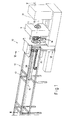
- Fig. 1 denotes a multi-spindle automatic lathe system, which essentially consist of a multi-spindle automatic lathe 11 and a device 12 for feeding material bars the automatic lathe 11.
- the device 12 its structure and the mode of operation is described in detail below, is the subject of the present invention.
- the device 12 a machine frame 13, inside of which a workpiece rod drum 14 rotatably arranged about a horizontal axis 15 is with the axis of rotation 16 of the spindle drum 17 of the Multi-spindle automatic lathes 11 are aligned.
- the multi-spindle automatic lathe is one with six workpiece spindles 18; accordingly is that Rod drum 14 with a total of six receiving boxes 19 for Workpiece bars 20 provided in the bar drum 14 so are arranged so that they with the spindle axes of the workpiece spindles 18 are aligned.
- the receiving boxes 19 take the workpiece bars 20 inside and are shared with the workpiece spindles are switched to the next position, when a processing step is carried out in the work area 21 the lathe 11 protruding workpieces is finished and the workpieces have to be brought into the next position, so that the next processing step can be carried out.
- the mode of operation of such multi-spindle automatic lathes together with the spindle drum advancing rod drum of a bar loading magazine is well known and should not explained in detail here.
- 2 is the feed and Feeding station 26 of the position of the lowest in plan view Assigned to the receiving box; 3 to 5 are all other receptacle boxes except the one in the feed and Feeding station located for the sake of better Clarity not shown.
- each receiving channel 28 or the receiving box forming it 19 is assigned a feed device 30, each Feed device with one in the associated receiving channel 28 received material rod holding clamping member 31 is that when the feed position 26 is reached in the feed direction 32 can be moved back and forth. The arrangement is taken so that the feed devices 30 accordingly the associated receptacle boxes 19 on the central support tube 22 are arranged and together with this and the receiving boxes be forwarded.
- the central support tube 22 with six evenly on its circumference arranged, in cross-section approximately T-shaped guide rails 33 provided, and the feed devices 30 have on its radial inside slide shoes 34, which the guide rails 33 include and slidable along these are.
- Feeding and loading station 26 located receiving box is the longitudinal mobility of the feed devices 30 in the other switching positions I. to V. by means of a circular segment or C-shaped locking element 35 prevented that from two approximately C-shaped disc elements 35a, b, which are fixedly mounted in the machine frame 13 and form a locking groove 36 between them.
- actuating cams 37 projecting radially outward as long as the clamping member is in one of the drum positions I. to V. located.
- clamping member 31 of the feed device 30 In the area of the feed and loading station 26 that is Locking element 35 interrupted and in the switch position VI. located clamping member 31 of the feed device 30 thus movable in the feed direction 32.
- the clamping member 31 ensures an actuator 38 with a circular segment-shaped sliding clamp 39, which has a guide groove 40, the dimensions of the Locking groove 36 is adapted.
- the sliding clamp is in the middle the switching operation of the rod drum 14 so in the mouth 41 of the C-shaped locking element 35 positioned that Guide groove and locking groove are aligned and the Cam from switch position V. to switch position VI. switched clamping member freely from the locking groove can run out and run into the guide groove.
- switched clamping member freely from the locking groove can run out and run into the guide groove.
- clamping member 31 opened and in the axial direction postponed.
- the machine's collet remains closed.
- an actuator not shown, moves such as a linear motor, a hydraulic cylinder, an adjusting spindle or the like.
- the actuator 38 the feed carriage 42 carrying the sliding clamp 39 the desired amount backwards to the later feed process to be able to execute, so in the direction of the multi-spindle lathe path.
- the clamping member 31 moved forward, i.e.
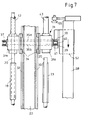
- the structure of the clamping members 31 is best shown in FIG. 7 up to 10. It can be seen that the clamping members 31 of the Feeders comparatively long to the lathe have pointing, tubular insertion portions 43.
- the push-in sections are in the rear bearing bodies 31a of the clamping members 31 rotatably mounted.
- the push-in sections 43 have at their front end a clamping ring 44, which is essentially of an outer cylinder part 45 and an inner Cylinder part 46 is formed.
- a clamping cylinder is the outer cylinder part back and forth reciprocally movable.
- the two cylinder parts are at the end with conical clamping surfaces 47, so that during an extension movement of the outer cylinder part (to the right in FIG. 9) this is radially compressed at its end and thereby firmly clamps the workpiece bar.
- the tension ring does not cause any axial movement when tensioning and relaxing , resulting in a particularly high positioning accuracy of the material bar is achieved.
- the outer diameter of the outer cylinder part 45 is dimensioned that this in the associated hollow workpiece spindle 18th can be pushed in from its rear end.
- the length of the two cylinder parts is such that the Operation of the automatic lathe system the front clamping rings 44 Push-in sections 43 as close as possible to the (not shown) Workpiece collets of the workpiece spindles of the automatic lathe are located.
- a Measuring device on the abutment device After installation of the new rod at stop 55, a Measuring device on the abutment device the rod length detected. Is this done and has the clamping member of the feed device the rod is tensioned, the abutment device moves back to their starting position, the stop element will pivoted out of the feed path, whereupon the feed device is brought into its front operating position (Fig. 5), in which the insertion section inside the hollow workpiece spindle the lathe is included and the front section 54 in the working space 21 of the machine for its processing protrudes.
- the two partial shells 23, 24 of the receiving box are closed, the temporary coupling of recording box and feed device is lifted and the new one Workpiece bar is made in the manner previously described processed.
- the clamping ring 44 is tensioned by relative displacement of the cylinder parts 45.46 to each other.
- the invention is by no means limited to such devices in which only in one of the spindle positions I to VI also a feed of the material bar is possible. Rather, it is the simplest way possible to feed at more than one spindle position realize. So in Figure 6 is an additional feed on the Spindle position III, i.e. offset by 180 ° to the feed station 26, a second feed station 57 indicated by dashed lines. A significant change in the overall construction of the The machine according to the invention is not connected to this. It is only necessary, the locking element 35 also in to interrupt this spindle position and in the interruption a second slide bracket 58 and an associated second actuator 59 to provide for this, which also at existing machines can be done by simple retrofitting measures can. The second actuating device 59 needs no travel distance as great as the first actuator to have, to implement the described Charging is required. Rather is enough the second actuator a travel path that the maximum Feed corresponds to that of the material bars to have.
- a driven, radially adjustable against the workpiece bar Actuator (not shown) to provide that, for example essentially from one of a drive preferably slow driven friction wheel can exist with the the workpiece bar is slowly rotated during the threading process is so that the flanks of the polygonal profile Align the clamping surfaces of the collets matched to this can.
- the friction wheel to be decoupled from its drive and it during of workpiece machining in plant pressed against the workpiece rod hold, which makes it able to vibrate dampen that occurs when the rod rotates.
- the device according to the invention is extremely flexible can be used and adapted to the requirements.
- Bar loading magazines such as feeding and separating the workpiece bars from a material store, Open the recording channels, move the recording boxes in axial direction, inserting the material bars by means of a Feed fingers in the insertion sections and also with others Additional units and functions can be combined. It must with the invention, the remnant of a material bar and the Feed unit are withdrawn less regularly more regularly than previously known bar loading magazines with their own material feed, so that the loading process takes place in a shorter time can.
- the machine according to the invention can be used both for automatic lathes used with its own material feed as well as for such where the material feed is carried out by the magazine becomes.
- the feed function becomes simple the feed device is overridden as soon as a new one Material bar inserted into the workpiece spindle of the automatic lathe and its feed device was handed over.
- the Bar loader according to the invention is thus both in its manufacture as well as its use by the user of the machine very simple and flexible, allows extensive Prefabrication of the individual system components and can easily can also be rebuilt later.
- the invention is not based on that shown and described Embodiment and not on its mode of operation limited. Other methods are also conceivable with which the new workpiece bar at the loading station in the Lathe is pushable. For example, it is possible at the rear end of the new rod a sliding abutment to provide on the machine frame that the new rod initially through the open clamping element of the feed device advances to a stop in the lathe's work area, to correctly position the new material bar. While the bar is held in this position, it will Clamping element positioned by the actuator so that the front overhang of the rod corresponds exactly to the dimension that is required to place the new workpiece bar in the work area the lathe into its desired machining position bring. The previously used stop in the work area is then no longer needed.
Applications Claiming Priority (2)
| Application Number | Priority Date | Filing Date | Title |
|---|---|---|---|
| DE10204518A DE10204518A1 (de) | 2002-02-05 | 2002-02-05 | Universale Vorrichtung zum Materialtransfer für Stangenlademagazine mit und ohne Vorschub für Mehrspindeldrehautomaten |
| DE10204518 | 2002-02-05 |
Publications (3)
| Publication Number | Publication Date |
|---|---|
| EP1332814A2 true EP1332814A2 (fr) | 2003-08-06 |
| EP1332814A3 EP1332814A3 (fr) | 2005-05-11 |
| EP1332814B1 EP1332814B1 (fr) | 2010-07-14 |
Family
ID=7713664
Family Applications (1)
| Application Number | Title | Priority Date | Filing Date |
|---|---|---|---|
| EP03001936A Expired - Lifetime EP1332814B1 (fr) | 2002-02-05 | 2003-01-30 | Dispositif d'avancement d'une barre pour tours d'usinage |
Country Status (3)
| Country | Link |
|---|---|
| EP (1) | EP1332814B1 (fr) |
| AT (1) | ATE473824T1 (fr) |
| DE (2) | DE10204518A1 (fr) |
Cited By (5)
| Publication number | Priority date | Publication date | Assignee | Title |
|---|---|---|---|---|
| ITMI20091230A1 (it) * | 2009-07-10 | 2011-01-11 | Cucchi Pietro Spa | Introduttore di barre per un tornio automatico |
| US8146465B2 (en) * | 2006-04-27 | 2012-04-03 | Lns S.A. | Installation for sequential loading of bars of material into a machining center |
| EP3417996A1 (fr) * | 2017-06-21 | 2018-12-26 | Gildemeister Italiana S.p.A. | Appareil de chargement de barre destiné à être utilisé avec une machine outil et machine-outil équipée d'un tel appareil chargeur de barre |
| US10737362B2 (en) | 2017-06-21 | 2020-08-11 | Gildemeister Italiana S.P.A. | Machine tool, in particular multi-spindle turning machine |
| US10786882B2 (en) | 2017-06-21 | 2020-09-29 | Gildemeister Italiana S.P.A. | Machine tool, in particular multi-spindle turning machine |
Families Citing this family (1)
| Publication number | Priority date | Publication date | Assignee | Title |
|---|---|---|---|---|
| CN113618467B (zh) * | 2021-07-15 | 2022-08-30 | 金石机器人银川有限公司 | 一种用于双主轴车床的接料机构 |
Citations (2)
| Publication number | Priority date | Publication date | Assignee | Title |
|---|---|---|---|---|
| FR2211310A1 (fr) | 1972-12-20 | 1974-07-19 | Iemca Spa | |
| DE4431814A1 (de) | 1994-09-07 | 1996-03-14 | Index Werke Kg Hahn & Tessky | Automatische Werkstoffstangen-Zuführeinrichtung für Werkzeugmaschinen, insbesondere Drehautomaten |
Family Cites Families (6)
| Publication number | Priority date | Publication date | Assignee | Title |
|---|---|---|---|---|
| CH446005A (fr) * | 1965-08-23 | 1967-10-31 | Esco Sa | Dispositif d'avance pour tour automatique |
| DE2803832A1 (de) * | 1978-01-30 | 1979-08-02 | Hagenuk Neufeldt Kuhnke Gmbh | Verriegelung fuer stangenvorschubeinrichtung fuer mehrspindel-drehautomaten |
| CH636030A5 (de) * | 1979-02-08 | 1983-05-13 | Tornos Sa Fabrique De Machine | Stangenfoermigen werkstoff verarbeitender drehautomat. |
| US5522689A (en) * | 1993-02-19 | 1996-06-04 | Pietro Cucchi S.P.A. | Device with improved bar guide for loading bars in automatic lathes |
| US5676031A (en) * | 1995-04-17 | 1997-10-14 | Logan Clutch Corp. | Apparatus for detecting stock |
| DE19916302A1 (de) * | 1999-04-12 | 2000-10-19 | Manfred Keck Praezisionsdrehte | CNC-gesteuertes Stangenlademagazin für Mehrspindeldrehautomaten |
-
2002
- 2002-02-05 DE DE10204518A patent/DE10204518A1/de not_active Withdrawn
-
2003
- 2003-01-30 AT AT03001936T patent/ATE473824T1/de not_active IP Right Cessation
- 2003-01-30 DE DE50312870T patent/DE50312870D1/de not_active Expired - Lifetime
- 2003-01-30 EP EP03001936A patent/EP1332814B1/fr not_active Expired - Lifetime
Patent Citations (3)
| Publication number | Priority date | Publication date | Assignee | Title |
|---|---|---|---|---|
| FR2211310A1 (fr) | 1972-12-20 | 1974-07-19 | Iemca Spa | |
| DE4431814A1 (de) | 1994-09-07 | 1996-03-14 | Index Werke Kg Hahn & Tessky | Automatische Werkstoffstangen-Zuführeinrichtung für Werkzeugmaschinen, insbesondere Drehautomaten |
| US5662014A (en) | 1994-09-07 | 1997-09-02 | Index-Werke Gmbh & Co., Kg Hahn & Tessky | Automatic bar stock feeding apparatus for machine tools, in particular automatic lathes |
Cited By (7)
| Publication number | Priority date | Publication date | Assignee | Title |
|---|---|---|---|---|
| US8146465B2 (en) * | 2006-04-27 | 2012-04-03 | Lns S.A. | Installation for sequential loading of bars of material into a machining center |
| ITMI20091230A1 (it) * | 2009-07-10 | 2011-01-11 | Cucchi Pietro Spa | Introduttore di barre per un tornio automatico |
| EP3417996A1 (fr) * | 2017-06-21 | 2018-12-26 | Gildemeister Italiana S.p.A. | Appareil de chargement de barre destiné à être utilisé avec une machine outil et machine-outil équipée d'un tel appareil chargeur de barre |
| JP2019038099A (ja) * | 2017-06-21 | 2019-03-14 | ギルドメイスター イタリアーナ ソシエタ ペル アチオニ | 工作機械と共に用いるためのバーローダ装置、及び、そのようなバーローダ装置を装備した工作機械 |
| US10737362B2 (en) | 2017-06-21 | 2020-08-11 | Gildemeister Italiana S.P.A. | Machine tool, in particular multi-spindle turning machine |
| US10737329B2 (en) | 2017-06-21 | 2020-08-11 | Gildemeister Italiana S.P.A. | Bar loader apparatus for use with a machine tool and machine tool equipped with such bar loader apparatus |
| US10786882B2 (en) | 2017-06-21 | 2020-09-29 | Gildemeister Italiana S.P.A. | Machine tool, in particular multi-spindle turning machine |
Also Published As
| Publication number | Publication date |
|---|---|
| DE50312870D1 (de) | 2010-08-26 |
| EP1332814A3 (fr) | 2005-05-11 |
| EP1332814B1 (fr) | 2010-07-14 |
| DE10204518A1 (de) | 2003-08-21 |
| ATE473824T1 (de) | 2010-07-15 |
Similar Documents
| Publication | Publication Date | Title |
|---|---|---|
| EP0700742B1 (fr) | Embarreur automatique pour machines-outil, en particulier pour tours automatiques | |
| DE10029749C2 (de) | Vorrichtung und Verfahren zum Beschicken und/oder Entnehmen von Werkstücken an einer Werkzeugmaschine | |
| EP0968069B2 (fr) | Machine-outil | |
| DE2540979C2 (de) | Automatische Werkzeugwechselvorrichtung für eine Vertikal- oder Karusselldrehmaschine | |
| DE1477501C3 (de) | Werkzeugmaschine mit Werkzeugwechselvorrichtung | |
| DE69923940T2 (de) | Verfahren zur Bearbeitung von Werkstücken und eine numerisch gesteuerte Drehmaschine | |
| EP0436949A1 (fr) | Dispositif d'alimentation des barres | |
| DE2642719A1 (de) | Verfahren und vorrichtung zum herstellen von drehbearbeiteten werkstuecken auf mehrstationen-schalttellermaschinen | |
| DE2015795A1 (de) | Verfahren und Vorrichtung zum Schneiden von Rohren und zum Abfasen der Schnittkanten | |
| DE2143780A1 (de) | Werkzeugwechseleinrichtung für Werkzeugmaschinen | |
| EP0340286B1 (fr) | Tour automatique de fa onnage de barres de materiaux | |
| CH659017A5 (de) | Mehrwerkstueck-drehautomat. | |
| CH697293B1 (de) | Drehmaschine, insbesondere Mehrspindeldrehautomat. | |
| DE2735429A1 (de) | Automatische werkzeugmaschine | |
| EP1332814B1 (fr) | Dispositif d'avancement d'une barre pour tours d'usinage | |
| DE2335605B2 (de) | Zu- und Abführeinrichtung für Werkstücke eines Mehrspindeldrehautomaten | |
| DE4228708C2 (de) | Numerisch gesteuertes Bearbeitungszentrum | |
| EP0023484B1 (fr) | Decolleteuse a alimentation de barres | |
| DE60021841T9 (de) | Stangenführung mit Plandrehvorrichtung der Stangen | |
| DE877689C (de) | Rohrbearbeitungsmaschine | |
| DE1502012A1 (de) | Werkstueckzufuehreinrichtung fuer Mehrspindel-Drehautomaten zum kopfseitigen Bearbeiten stangenfoermiger Werkstuecke | |
| DE3204886C1 (de) | Mehrwerkstück-Drehautomat | |
| DE1652738A1 (de) | Verfahren und Vorrichtung zum automatischen Vorschub von Stangenmaterial | |
| DE1527172A1 (de) | Einrichtung zum Vorzentrieren zylindrischer Werkstuecke auf einer Gewindeschneidmaschine | |
| DE2109157C3 (de) | Werkzeugmaschine zum Herstellen von selbstschneidenden Gewindebüchsen |
Legal Events
| Date | Code | Title | Description |
|---|---|---|---|
| PUAI | Public reference made under article 153(3) epc to a published international application that has entered the european phase |
Free format text: ORIGINAL CODE: 0009012 |
|
| AK | Designated contracting states |
Designated state(s): AT BE BG CH CY CZ DE DK EE ES FI FR GB GR HU IE IT LI LU MC NL PT SE SI SK TR |
|
| AX | Request for extension of the european patent |
Extension state: AL LT LV MK RO |
|
| PUAL | Search report despatched |
Free format text: ORIGINAL CODE: 0009013 |
|
| AK | Designated contracting states |
Kind code of ref document: A3 Designated state(s): AT BE BG CH CY CZ DE DK EE ES FI FR GB GR HU IE IT LI LU MC NL PT SE SI SK TR |
|
| AX | Request for extension of the european patent |
Extension state: AL LT LV MK RO |
|
| 17P | Request for examination filed |
Effective date: 20051013 |
|
| AKX | Designation fees paid |
Designated state(s): AT BE BG CH CY CZ DE DK EE ES FI FR GB GR HU IE IT LI LU MC NL PT SE SI SK TR |
|
| 17Q | First examination report despatched |
Effective date: 20061026 |
|
| GRAP | Despatch of communication of intention to grant a patent |
Free format text: ORIGINAL CODE: EPIDOSNIGR1 |
|
| GRAS | Grant fee paid |
Free format text: ORIGINAL CODE: EPIDOSNIGR3 |
|
| GRAA | (expected) grant |
Free format text: ORIGINAL CODE: 0009210 |
|
| AK | Designated contracting states |
Kind code of ref document: B1 Designated state(s): AT BE BG CH CY CZ DE DK EE ES FI FR GB GR HU IE IT LI LU MC NL PT SE SI SK TR |
|
| REG | Reference to a national code |
Ref country code: GB Ref legal event code: FG4D Free format text: NOT ENGLISH |
|
| REG | Reference to a national code |
Ref country code: CH Ref legal event code: EP |
|
| REG | Reference to a national code |
Ref country code: IE Ref legal event code: FG4D |
|
| REF | Corresponds to: |
Ref document number: 50312870 Country of ref document: DE Date of ref document: 20100826 Kind code of ref document: P |
|
| REG | Reference to a national code |
Ref country code: NL Ref legal event code: VDEP Effective date: 20100714 |
|
| PG25 | Lapsed in a contracting state [announced via postgrant information from national office to epo] |
Ref country code: FI Free format text: LAPSE BECAUSE OF FAILURE TO SUBMIT A TRANSLATION OF THE DESCRIPTION OR TO PAY THE FEE WITHIN THE PRESCRIBED TIME-LIMIT Effective date: 20100714 Ref country code: NL Free format text: LAPSE BECAUSE OF FAILURE TO SUBMIT A TRANSLATION OF THE DESCRIPTION OR TO PAY THE FEE WITHIN THE PRESCRIBED TIME-LIMIT Effective date: 20100714 |
|
| REG | Reference to a national code |
Ref country code: IE Ref legal event code: FD4D |
|
| PG25 | Lapsed in a contracting state [announced via postgrant information from national office to epo] |
Ref country code: CY Free format text: LAPSE BECAUSE OF FAILURE TO SUBMIT A TRANSLATION OF THE DESCRIPTION OR TO PAY THE FEE WITHIN THE PRESCRIBED TIME-LIMIT Effective date: 20100714 Ref country code: PT Free format text: LAPSE BECAUSE OF FAILURE TO SUBMIT A TRANSLATION OF THE DESCRIPTION OR TO PAY THE FEE WITHIN THE PRESCRIBED TIME-LIMIT Effective date: 20101115 Ref country code: SI Free format text: LAPSE BECAUSE OF FAILURE TO SUBMIT A TRANSLATION OF THE DESCRIPTION OR TO PAY THE FEE WITHIN THE PRESCRIBED TIME-LIMIT Effective date: 20100714 Ref country code: BG Free format text: LAPSE BECAUSE OF FAILURE TO SUBMIT A TRANSLATION OF THE DESCRIPTION OR TO PAY THE FEE WITHIN THE PRESCRIBED TIME-LIMIT Effective date: 20101014 |
|
| PG25 | Lapsed in a contracting state [announced via postgrant information from national office to epo] |
Ref country code: GR Free format text: LAPSE BECAUSE OF FAILURE TO SUBMIT A TRANSLATION OF THE DESCRIPTION OR TO PAY THE FEE WITHIN THE PRESCRIBED TIME-LIMIT Effective date: 20101015 Ref country code: SE Free format text: LAPSE BECAUSE OF FAILURE TO SUBMIT A TRANSLATION OF THE DESCRIPTION OR TO PAY THE FEE WITHIN THE PRESCRIBED TIME-LIMIT Effective date: 20100714 |
|
| PG25 | Lapsed in a contracting state [announced via postgrant information from national office to epo] |
Ref country code: DK Free format text: LAPSE BECAUSE OF FAILURE TO SUBMIT A TRANSLATION OF THE DESCRIPTION OR TO PAY THE FEE WITHIN THE PRESCRIBED TIME-LIMIT Effective date: 20100714 Ref country code: IE Free format text: LAPSE BECAUSE OF FAILURE TO SUBMIT A TRANSLATION OF THE DESCRIPTION OR TO PAY THE FEE WITHIN THE PRESCRIBED TIME-LIMIT Effective date: 20100714 |
|
| PLBE | No opposition filed within time limit |
Free format text: ORIGINAL CODE: 0009261 |
|
| STAA | Information on the status of an ep patent application or granted ep patent |
Free format text: STATUS: NO OPPOSITION FILED WITHIN TIME LIMIT |
|
| PG25 | Lapsed in a contracting state [announced via postgrant information from national office to epo] |
Ref country code: SK Free format text: LAPSE BECAUSE OF FAILURE TO SUBMIT A TRANSLATION OF THE DESCRIPTION OR TO PAY THE FEE WITHIN THE PRESCRIBED TIME-LIMIT Effective date: 20100714 Ref country code: EE Free format text: LAPSE BECAUSE OF FAILURE TO SUBMIT A TRANSLATION OF THE DESCRIPTION OR TO PAY THE FEE WITHIN THE PRESCRIBED TIME-LIMIT Effective date: 20100714 |
|
| PGFP | Annual fee paid to national office [announced via postgrant information from national office to epo] |
Ref country code: FR Payment date: 20110401 Year of fee payment: 9 Ref country code: DE Payment date: 20110316 Year of fee payment: 9 Ref country code: CZ Payment date: 20110321 Year of fee payment: 9 Ref country code: CH Payment date: 20110328 Year of fee payment: 9 |
|
| 26N | No opposition filed |
Effective date: 20110415 |
|
| PG25 | Lapsed in a contracting state [announced via postgrant information from national office to epo] |
Ref country code: ES Free format text: LAPSE BECAUSE OF FAILURE TO SUBMIT A TRANSLATION OF THE DESCRIPTION OR TO PAY THE FEE WITHIN THE PRESCRIBED TIME-LIMIT Effective date: 20101025 |
|
| REG | Reference to a national code |
Ref country code: DE Ref legal event code: R097 Ref document number: 50312870 Country of ref document: DE Effective date: 20110415 |
|
| PGFP | Annual fee paid to national office [announced via postgrant information from national office to epo] |
Ref country code: GB Payment date: 20110324 Year of fee payment: 9 |
|
| BERE | Be: lapsed |
Owner name: EUGEN OSTERTAG MASCHINEN-HERSTELLUNG GERATEBAU G. Effective date: 20110131 |
|
| PG25 | Lapsed in a contracting state [announced via postgrant information from national office to epo] |
Ref country code: MC Free format text: LAPSE BECAUSE OF NON-PAYMENT OF DUE FEES Effective date: 20110131 |
|
| PGFP | Annual fee paid to national office [announced via postgrant information from national office to epo] |
Ref country code: IT Payment date: 20110330 Year of fee payment: 9 |
|
| PG25 | Lapsed in a contracting state [announced via postgrant information from national office to epo] |
Ref country code: BE Free format text: LAPSE BECAUSE OF NON-PAYMENT OF DUE FEES Effective date: 20110131 |
|
| REG | Reference to a national code |
Ref country code: AT Ref legal event code: MM01 Ref document number: 473824 Country of ref document: AT Kind code of ref document: T Effective date: 20110130 |
|
| REG | Reference to a national code |
Ref country code: CH Ref legal event code: PL |
|
| GBPC | Gb: european patent ceased through non-payment of renewal fee |
Effective date: 20120130 |
|
| REG | Reference to a national code |
Ref country code: FR Ref legal event code: ST Effective date: 20120928 |
|
| PG25 | Lapsed in a contracting state [announced via postgrant information from national office to epo] |
Ref country code: LI Free format text: LAPSE BECAUSE OF NON-PAYMENT OF DUE FEES Effective date: 20120131 Ref country code: CH Free format text: LAPSE BECAUSE OF NON-PAYMENT OF DUE FEES Effective date: 20120131 Ref country code: DE Free format text: LAPSE BECAUSE OF NON-PAYMENT OF DUE FEES Effective date: 20120801 Ref country code: GB Free format text: LAPSE BECAUSE OF NON-PAYMENT OF DUE FEES Effective date: 20120130 Ref country code: CZ Free format text: LAPSE BECAUSE OF NON-PAYMENT OF DUE FEES Effective date: 20120130 |
|
| REG | Reference to a national code |
Ref country code: DE Ref legal event code: R119 Ref document number: 50312870 Country of ref document: DE Effective date: 20120801 |
|
| PG25 | Lapsed in a contracting state [announced via postgrant information from national office to epo] |
Ref country code: IT Free format text: LAPSE BECAUSE OF NON-PAYMENT OF DUE FEES Effective date: 20120130 |
|
| PG25 | Lapsed in a contracting state [announced via postgrant information from national office to epo] |
Ref country code: FR Free format text: LAPSE BECAUSE OF NON-PAYMENT OF DUE FEES Effective date: 20120131 |
|
| PG25 | Lapsed in a contracting state [announced via postgrant information from national office to epo] |
Ref country code: AT Free format text: LAPSE BECAUSE OF NON-PAYMENT OF DUE FEES Effective date: 20110130 |
|
| PG25 | Lapsed in a contracting state [announced via postgrant information from national office to epo] |
Ref country code: LU Free format text: LAPSE BECAUSE OF NON-PAYMENT OF DUE FEES Effective date: 20110130 |
|
| PG25 | Lapsed in a contracting state [announced via postgrant information from national office to epo] |
Ref country code: TR Free format text: LAPSE BECAUSE OF FAILURE TO SUBMIT A TRANSLATION OF THE DESCRIPTION OR TO PAY THE FEE WITHIN THE PRESCRIBED TIME-LIMIT Effective date: 20100714 |
|
| PG25 | Lapsed in a contracting state [announced via postgrant information from national office to epo] |
Ref country code: HU Free format text: LAPSE BECAUSE OF FAILURE TO SUBMIT A TRANSLATION OF THE DESCRIPTION OR TO PAY THE FEE WITHIN THE PRESCRIBED TIME-LIMIT Effective date: 20100714 |