EP1332811B1 - Mould pipe - Google Patents
Mould pipe Download PDFInfo
- Publication number
- EP1332811B1 EP1332811B1 EP03000356A EP03000356A EP1332811B1 EP 1332811 B1 EP1332811 B1 EP 1332811B1 EP 03000356 A EP03000356 A EP 03000356A EP 03000356 A EP03000356 A EP 03000356A EP 1332811 B1 EP1332811 B1 EP 1332811B1
- Authority
- EP
- European Patent Office
- Prior art keywords
- mould pipe
- transition regions
- water
- wall thickness
- pipe according
- Prior art date
- Legal status (The legal status is an assumption and is not a legal conclusion. Google has not performed a legal analysis and makes no representation as to the accuracy of the status listed.)
- Expired - Lifetime
Links
Images

Classifications
-
- B—PERFORMING OPERATIONS; TRANSPORTING
- B22—CASTING; POWDER METALLURGY
- B22D—CASTING OF METALS; CASTING OF OTHER SUBSTANCES BY THE SAME PROCESSES OR DEVICES
- B22D11/00—Continuous casting of metals, i.e. casting in indefinite lengths
- B22D11/04—Continuous casting of metals, i.e. casting in indefinite lengths into open-ended moulds
- B22D11/0406—Moulds with special profile
Definitions
- the invention relates to a mold tube with a double-T-shaped inner and outer cross-section in the beam blank format according to the features in the preamble of patent claim 1.
- the material temperatures in the mold wall resulting from the heat loads occurring during continuous casting and the cooling conditions by the respective cooling medium which usually in the form of water in a water gap between a matched to the outer contour of the mold tube Wasserleitmantel and the outside surface of the Kokillenrohrs flows from bottom to top, this absorbs the heat accumulated and transported away.
- the removal of heat by means of cooling water is largely determined by the water velocity in the water gap.
- the invention is - based on the prior art - the object of the invention to provide a mold tube with a double-T-shaped inner and outer cross section in the beam blank format for continuous casting of metals, in which a local overheating of the transition areas avoided and thereby a longer life is achieved.
- the features of claim 2 provide that the wall thickness is reduced in the transition areas only in the height range of the bathroom mirror.
- the reduction of the wall thickness of the mold tube in the rounded transition areas can be done in various ways.
- trough-shaped recesses are provided outside of the transition areas.
- the curvature of the recesses in this case can be largely adapted to the curvature of the inner surface of the transition regions.
- the wall thickness reduction in the form of trough-shaped recesses has the advantage that the outer surface of the mold tube is increased, so that an even better cooling effect can be achieved.
- a plurality of longitudinally directed, adjacent grooves are provided on the outside of the transition regions.
- the cross-section and / or the depth of the grooves may be the same or different in each transition region.
- the cross section of the grooves may be rounded or angular, e.g. be triangular.
- a plurality of longitudinally directed, side by side extending bores are provided to reduce the wall thickness in the wall portions of the transition regions.
- the size of the holes, their number, the distance from each other and also their position in relation to the outer or inner contour of the Kokillenrohrs may vary. It is advantageous, however, if the holes have a greater proximity to the outer surface than to the inner surface of the mold tube.
- the embodiment according to the features of claim 6 provides that the Wasserleitmantel has a rectangular cross-section and between the Wasserleitmantel and the webs or flanges are incorporated into the formed by the outer contour of the Kokillenrohrs and the inner contour of the Wasserleitmantels cross-sectional area matched patches.
- a mold tube with a double-T-shaped inner and outer cross-section in the beam blank format is denoted by 1 in FIGS.
- the mold tube 1 is used for continuous casting of metals.
- the curvature of the mold tube 1 is not shown in the longitudinal direction.
- the wall thickness D of the mold tube 1 in the rounded transitional areas 2 is smaller than the wall thickness D1 in the remaining wall sections, from the central webs 4, which are located opposite one another and are inclined towards the longitudinal axis 3, on the adjacent inclined flanges 5 6 and 7.
- the wall thickness reduction takes place in the embodiment of Figures 1 to 3, characterized in that the outside of the transition regions 2 longitudinally directed trough-shaped recesses 8 are provided. These recesses 8 extend, as the figure 2 reveals, only in the height range of the not further illustrated bath mirror.
- the curvature 9 of the recesses 8 is largely adapted to the curvature 10 of the inner surface 11 of the mold tube 1 in the transition regions 2.
- these channels 15 are provided with patches 17, which in the upper area also are adapted to the trough-shaped recesses 8.
- FIG. 4 Four different embodiments are shown in FIG. 4, as the wall thickness reduction of the mold tube 1 can also be realized.
- a plurality of longitudinally directed, adjacent grooves 18, 18a, 18b are provided on the outside. While in the transition region 2a, the grooves 18 have a triangular cross-section, the grooves 18a, 18b in the transition regions 2b, 2c have rounded bottoms. In this case, the grooves 18b have a greater depth in the transition region 2c than the grooves 18a in the transition region 2b.
- the wall thickness reduction is realized by holes 19. These holes 19 are closer to the outer surface 13 of the mold tube 1 as the inner surface eleventh
- Both the grooves 18, 18a, 18b and the holes 19 extend, as the recesses 8, only in the height range of the bath level.
Abstract
Description
Die Erfindung betrifft ein Kokillenrohr mit einem Doppel-T-förmigen Innen- und Außenquerschnitt im Beam-Blank-Format gemäß den Merkmalen im Oberbegriff des Patentanspruchs 1.The invention relates to a mold tube with a double-T-shaped inner and outer cross-section in the beam blank format according to the features in the preamble of
Beim Stranggießen von Metallen mit einem Kokillenrohr ergeben sich die Materialtemperaturen in der Kokillenwand aus den beim Stranggießen auftretenden Wärmebelastungen und den Kühlbedingungen durch das jeweilige Kühlmedium, was in aller Regel in Form von Wasser in einem Wasserspalt zwischen einem an die Außenkontur des Kokillenrohrs angepaßten Wasserleitmantel und der äußeren Oberfläche des Kokillenrohrs von unten nach oben strömt, hierbei die anfallende Wärme aufnimmt und abtransportiert. Die Abfuhr der Wärme mittels Kühlwasser wird weitgehend durch die Wassergeschwindigkeit im Wasserspalt bestimmt.In the continuous casting of metals with a mold tube, the material temperatures in the mold wall resulting from the heat loads occurring during continuous casting and the cooling conditions by the respective cooling medium, which usually in the form of water in a water gap between a matched to the outer contour of the mold tube Wasserleitmantel and the outside surface of the Kokillenrohrs flows from bottom to top, this absorbs the heat accumulated and transported away. The removal of heat by means of cooling water is largely determined by the water velocity in the water gap.
Beim Stranggießen von Metallen mit einem Kokillenrohr der in Rede stehenden Gattung hat man beobachtet, daß aufgrund der speziellen Geometrie des Beam-Blank-Formats extreme lokale Wärmebelastungen in den Übergangsbereichen von den einander frontal gegenüber liegenden, zur Längsachse hin eingezogenen mittleren Stegen auf die angrenzenden schräg gestellten Flansche auftreten. Diese lokalen Wärmebelastungen führen bei ungünstigen geometrischen Verhältnissen der Übergangsbereiche zu einer Überhitzung des Kokillenrohrs und demzufolge zu einer drastischen Reduzierung seiner Standzeit.In the continuous casting of metals with a mold tube of the type in question it has been observed that due to the special geometry of the beam blank format extreme local heat loads in the transition areas of the frontally opposite, retracted to the longitudinal axis center webs on the adjacent oblique Asked flanges occur. These local heat loads lead in unfavorable geometric conditions of the transition areas to overheating of the mold tube and consequently to a drastic reduction in its life.
Der Erfindung liegt - ausgehend vom Stand der Technik - die Aufgabe zugrunde, ein Kokillenrohr mit einem Doppel-T-förmigen Innen- und Außenquerschnitt im Beam-Blank-Format zum Stranggießen von Metallen zu schaffen, bei welchem eine lokale Überhitzung der Übergangsbereiche vermieden und dadurch eine längere Standzeit erzielt wird.The invention is - based on the prior art - the object of the invention to provide a mold tube with a double-T-shaped inner and outer cross section in the beam blank format for continuous casting of metals, in which a local overheating of the transition areas avoided and thereby a longer life is achieved.
Diese Aufgabe wird mit den im kennzeichnenden Teil des Patentanspruchs 1 angegebenen Merkmalen gelöst.This object is achieved with the features stated in the characterizing part of
Durch die zumindest partielle Reduzierung der Wanddicke des Kokillenrohrs in den gerundeten Übergangsbereichen wird hier eine deutlich verbesserte Wärmeabfuhr erreicht, damit eine lokale Überhitzung der Übergangsbereiche vermieden und folglich die Standzeit des Kokillenrohrs deutlich heraufgesetzt.Due to the at least partial reduction of the wall thickness of the mold tube in the rounded transition areas a significantly improved heat dissipation is achieved here, thus avoiding local overheating of the transition areas and consequently significantly increases the service life of the mold tube.
Im Hinblick darauf, daß beim Stranggießen von Metallen die höchste Wärmebelastung im Kokillenrohr in der Regel im Höhenbereich des Badspiegels auftritt, sehen die Merkmale des Patentanspruchs 2 vor, daß die Wanddicke in den Übergangsbereichen nur im Höhenbereich des Badspiegels reduziert ist.In view of the fact that in the continuous casting of metals, the highest heat load in the mold tube usually occurs in the height range of the bathroom mirror, the features of
Die Reduzierung der Wanddicke des Kokillenrohrs in den gerundeten Übergangsbereichen kann auf verschiedene Art und Weise erfolgen.The reduction of the wall thickness of the mold tube in the rounded transition areas can be done in various ways.
Entsprechend den Merkmalen des Patentanspruchs 3 sind außenseitig der Übergangsbereiche längs gerichtete muldenförmige Aussparungen vorgesehen. Die Krümmung der Aussparungen kann hierbei weitgehend an die Krümmung der inneren Oberfläche der Übergangsbereiche angepaßt sein. Außerdem hat die Wanddickenreduzierung in Form von muldenförmigen Aussparungen den Vorteil, daß die äußere Oberfläche des Kokillenrohrs vergrößert wird, so daß ein noch besserer Kühleffekt erreichbar ist.According to the features of
Eine weitere Möglichkeit der Wanddickenreduzierung wird in den Merkmalen des Patentanspruchs 4 erblickt. Danach sind außenseitig der Übergangsbereiche mehrere längs gerichtete, nebeneinander verlaufende Nuten vorgesehen. Der Querschnitt und/oder die Tiefe der Nuten kann in jedem Übergangsbereich gleich oder unterschiedlich bemessen sein. Der Querschnitt der Nuten kann gerundet oder eckig, z.B. dreieckförmig sein.Another way of reducing wall thickness is seen in the features of
Ferner ist es entsprechend den Merkmalen des Patentanspruchs 5 denkbar, daß zur Wanddickenreduzierung in den Wandabschnitten der Übergangsbereiche mehrere längs gerichtete, nebeneinander verlaufende Bohrungen vorgesehen sind. Die Größe der Bohrungen, ihre Anzahl, der Abstand zueinander und auch ihre Lage in Relation zur Außen- bzw. Innenkontur des Kokillenrohrs kann variieren. Vorteilhaft ist es jedoch, wenn die Bohrungen eine größere Nähe zur äußeren Oberfläche als zur inneren Oberfläche des Kokillenrohrs haben.Further, it is conceivable according to the features of
Da die Abfuhr der Wärme mittels Kühlwasser - wie bekannt - durch die Wassergeschwindigkeit im Wasserspalt zwischen dem Kokillenrohr und dem Wasserleitmantel bestimmt wird, sollte dieser Wasserspalt auch im Bereich der Wanddickenreduzierung eingehalten werden, um eine gleichmäßige Wassergeschwindigkeit im gesamten Wasserspalt zu garantieren. Insofern sieht die Ausführungsform gemäß den Merkmalen des Patentanspruchs 6 vor, daß der Wasserleitmantel einen rechteckigen Querschnitt aufweist und zwischen den Wasserleitmantel sowie die Stege bzw. die Flansche an den durch die Außenkontur des Kokillenrohrs sowie die Innenkontur des Wasserleitmantels gebildeten Querschnittsbereich angepaßte Füllstücke eingegliedert sind.Since the removal of heat by means of cooling water - as known - is determined by the water velocity in the water gap between the mold tube and the water jacket, this water gap should also be maintained in the wall thickness reduction to guarantee a uniform water velocity throughout the water gap. In this respect, the embodiment according to the features of
Die Erfindung ist nachfolgend anhand von in den Zeichnungen dargestellten Ausführungsbeispielen näher erläutert. Es zeigen:
Figur 1- in schematischer Perspektive ein Kokillenrohr im Beam-Blank-Format ohne Wasserleitmantel mit seitlichen Füllstücken;
Figur 2- ebenfalls in schematischer Perspektive das Kokillenrohr der
Figur 1 mit gesondert dargestelltem Füllstück; Figur 3- eine Draufsicht auf ein Kokillenrohr ohne Abschlußdeckel im Bereich der seitlichen Kanäle, jedoch mit Wasserleitmantel und
Figur 4- eine Draufsicht auf ein Kokillenrohr gemäß weiteren Ausführungsformen ohne Abschlußdeckel und Wasserleitmantel.
- FIG. 1
- in a schematic perspective, a mold tube in the beam blank format without Wasserleitmantel with lateral filling pieces;
- FIG. 2
- also in a schematic perspective, the mold tube of Figure 1 with separately Pictured filler;
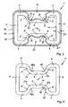
- FIG. 3
- a plan view of a mold tube without cover in the region of the side channels, but with Wasserleitmantel and
- FIG. 4
- a plan view of a mold tube according to other embodiments without end cap and Wasserleitmantel.
Mit 1 ist in den Figuren 1 bis 4 ein Kokillenrohr mit einem Doppel-T-förmigen Innenund Außenquerschnitt im Beam-Blank-Format bezeichnet. Das Kokillenrohr 1 dient zum Stranggießen von Metallen. In den Figuren 3 und 4 ist die Krümmung des Kokillenrohrs 1 in Längsrichtung nicht dargestellt.1, a mold tube with a double-T-shaped inner and outer cross-section in the beam blank format is denoted by 1 in FIGS. The
Wie Figur 3 näher erkennen läßt, ist die Wanddicke D des Kokillenrohrs 1 in den gerundeten Übergangsbereichen 2 von den einander frontal gegenüber liegenden, zur Längsachse 3 hin eingezogenen mittleren Stegen 4 auf die angrenzenden schräg gestellten Flansche 5 geringer als die Wanddicke D1 in den restlichen Wandabschnitten 6 und 7 bemessen.As can be seen in more detail in FIG. 3, the wall thickness D of the
Die Wanddickenreduzierung erfolgt bei der Ausführungsform der Figuren 1 bis 3 dadurch, daß außenseitig der Übergangsbereiche 2 längs gerichtete muldenförmige Aussparungen 8 vorgesehen sind. Diese Aussparungen 8 erstrecken sich, wie die Figur 2 erkennen läßt, lediglich im Höhenbereich des nicht näher veranschaulichten Badspiegels. Die Krümmung 9 der Aussparungen 8 ist weitgehend an die Krümmung 10 der inneren Oberfläche 11 des Kokillenrohrs 1 in den Übergangsbereichen 2 angepaßt.The wall thickness reduction takes place in the embodiment of Figures 1 to 3, characterized in that the outside of the
Umfangsseitig des Kokillenrohrs 1 befindet sich ein nur aus der Figur 3 erkennbarer Wasserleitmantel 12 mit einem im wesentlichen rechteckigen Querschnitt. Zwischen dem Wasserleitmantel 12 und der äußeren Oberfläche 13 des Kokillenrohrs 1 wird ein Wasserspalt 14 gebildet, durch den Kühlwasser von unten nach oben mit einer vorbestimmten Wassergeschwindigkeit geführt wird.On the circumference of the
Damit auch in den seitlichen Kanälen 15 des Kokillenrohrs 1, welche gemäß den Figuren 1 und 2 am oberen Ende durch Abschlußdeckel 16 verschlossen sind, eine gleichmäßige Wassergeschwindigkeit im Wasserspalt 14 erreicht wird, werden diese Kanäle 15 mit Füllstücken 17 versehen, die im oberen Bereich auch an die muldenförmigen Aussparungen 8 angepaßt sind.Thus even in the
In der Figur 4 sind vier verschiedene Ausführungsformen dargestellt, wie die Wanddickenreduzierung des Kokillenrohrs 1 auch noch realisiert werden kann.Four different embodiments are shown in FIG. 4, as the wall thickness reduction of the
In den Übergangsbereichen 2a, 2b, 2c sind außenseitig mehrere längs gerichtete, nebeneinander verlaufende Nuten 18, 18a, 18b vorgesehen. Während in dem Übergangsbereich 2a die Nuten 18 einen dreieckförmigen Querschnitt haben, besitzen die Nuten 18a, 18b in den Übergangsbereichen 2b, 2c gerundete Böden. Dabei haben die Nuten 18b im Übergangsbereich 2c eine größere Tiefe als die Nuten 18a im Übergangsbereich 2b.In the
Im Übergangsbereich 2d ist die Wanddickenreduzierung durch Bohrungen 19 realisiert. Diese Bohrungen 19 liegen näher zur äußeren Oberfläche 13 des Kokillenrohrs 1 als zur inneren Oberfläche 11.In the
Sowohl die Nuten 18, 18a, 18b als auch die Bohrungen 19 erstrecken sich, wie die Aussparungen 8, nur im Höhenbereich des Badspiegels.Both the
- 1 -1 -
- KokillenrohrMold pipe
- 2 -2 -
- ÜbergangsbereicheTransition areas
- 2a -2a -
- ÜbergangsbereichTransition area
- 2b -2 B -
- ÜbergangsbereichTransition area
- 2c -2c -
- ÜbergangsbereichTransition area
- 2d -2d -
- ÜbergangsbereichTransition area
- 3 -3 -
- Längsachse v. 1Longitudinal axis v. 1
- 4 -4 -
- StegeStege
- 5 -5 -
- Flanscheflanges
- 6 -6 -
- Wandabschnitte v. 1Wall sections v. 1
- 7 -7 -
- Wandabschnitte v. 1Wall sections v. 1
- 8 -8th -
- Aussparungen in 2Recesses in 2
- 9 -9 -
- Krümmung v. 8Curvature v. 8th
- 10 -10 -
- Krümmung v. 2Curvature v. 2
- 11 -11 -
- innere Oberfläche v. 1inner surface v. 1
- 12 -12 -
- WasserleitmantelWasserleitmantel
- 13 -13 -
- äußere Oberfläche v. 1outer surface v. 1
- 14 -14 -
- Wasserspaltwater gap
- 15 -15 -
- Kanälechannels
- 16 -16 -
- Abschlußdeckelend cover
- 17 -17 -
- Füllstückefiller
- 18 -18 -
- Nuten in 2aGrooves in 2a
- 18a -18a -
- Nuten in 2bGrooves in 2b
- 18b -18b -
- Nuten in 2cGrooves in 2c
- 19 -19 -
- Bohrungen in 2dDrilling in 2d
- D -D -
- Wanddicke v. 1 in 2Wall thickness v. 1 in 2
- D1 -D1 -
- Wanddicke v. 1 in 6, 7Wall thickness v. 1 in 6, 7
Claims (6)
- Mould pipe comprising a double T-shaped inner and outer cross section in beam blank format, which is surrounded by a water-guiding jacket (12) adapted to its outer contour while forming a water gap (14), characterised in that the wall thickness (D) of the mould pipe (1) in the rounded transition regions (2, 2a, 2b, 2c, 2d) from the middle webs (4) opposing one another frontally and drawn in toward the longitudinal axis (3), to the adjacent obliquely positioned flanges (5) is dimensioned at least partially smaller than in the remaining wall portions (6, 7).
- Mould pipe according to claim 1, characterised in that the wall thickness (D) in the transition regions (2, 2a, 2b, 2c, 2d) is only reduced in the height range of the bath level.
- Mould pipe according to claim 1 or 2, characterised in that longitudinally directed trough-like recesses (8) are provided on the outside of the transition regions (2).
- Mould pipe according to claim 1 or 2, characterised in that a plurality of longitudinally directed grooves (18, 18a, 18b) extending next to one another are provided on the outside of the transition regions (2a, 2b, 2c).
- Mould pipe according to claim 1 or 2, characterised in that a plurality of longitudinally directed bores (19) extending next to one another are provided in the wall sections of the transition regions (2d).
- Mould pipe according to any one of claims 1 to 5, characterised in that the water-guiding jacket (12) has a substantially rectangular cross section and filler pieces (17) adapted to the cross sectional region formed by the outer contour of the mould pipe (1) and the inner contour of the water-guiding jacket (12) are incorporated between the water-guiding jacket (12) and the webs (4) or the flanges (5).
Applications Claiming Priority (2)
| Application Number | Priority Date | Filing Date | Title |
|---|---|---|---|
| DE10203967 | 2002-01-31 | ||
| DE10203967A DE10203967A1 (en) | 2002-01-31 | 2002-01-31 | Mold pipe |
Publications (3)
| Publication Number | Publication Date |
|---|---|
| EP1332811A2 EP1332811A2 (en) | 2003-08-06 |
| EP1332811A3 EP1332811A3 (en) | 2003-08-20 |
| EP1332811B1 true EP1332811B1 (en) | 2007-10-24 |
Family
ID=7713506
Family Applications (1)
| Application Number | Title | Priority Date | Filing Date |
|---|---|---|---|
| EP03000356A Expired - Lifetime EP1332811B1 (en) | 2002-01-31 | 2003-01-09 | Mould pipe |
Country Status (15)
| Country | Link |
|---|---|
| US (2) | US20030141430A1 (en) |
| EP (1) | EP1332811B1 (en) |
| JP (1) | JP2003225741A (en) |
| KR (1) | KR20030065403A (en) |
| CN (1) | CN1248802C (en) |
| AT (1) | ATE376465T1 (en) |
| BR (1) | BR0300258A (en) |
| CA (1) | CA2415517C (en) |
| DE (3) | DE20219419U1 (en) |
| DK (1) | DK1332811T3 (en) |
| ES (1) | ES2291549T3 (en) |
| MX (1) | MXPA03000876A (en) |
| PT (1) | PT1332811E (en) |
| RU (1) | RU2304485C2 (en) |
| TW (1) | TWI259114B (en) |
Families Citing this family (10)
| Publication number | Priority date | Publication date | Assignee | Title |
|---|---|---|---|---|
| US20090037655A1 (en) * | 2007-07-30 | 2009-02-05 | Dell Products L.P. | System and Method for Data Storage and Backup |
| DE102008007082A1 (en) * | 2007-11-01 | 2009-05-07 | Kme Germany Ag & Co. Kg | Liquid-cooled mold for continuous casting of metals |
| EP2483606B1 (en) | 2009-09-29 | 2018-01-17 | Carrier Corporation | System and method for maintaining air temperature within a building hvac system |
| DE202012004204U1 (en) * | 2011-05-03 | 2012-06-15 | Central Iron & Steel Research Institute | Bevelled narrow-side copper plate for casting mold with funnel-shaped curved surface |
| DE102011106313A1 (en) * | 2011-06-27 | 2012-12-27 | Kme Germany Ag & Co. Kg | Method for producing a mold tube |
| CN102974782B (en) * | 2012-12-14 | 2015-01-21 | 莱芜钢铁集团有限公司 | H-shaped tubular mold |
| CN108356239A (en) * | 2018-03-21 | 2018-08-03 | 马鞍山钢铁股份有限公司 | A kind of special-shaped billet continuous casting machine crystallizer copper pipe and its manufacturing method |
| CN109794586B (en) * | 2019-02-27 | 2023-10-03 | 山东钢铁股份有限公司 | Crystallizer suitable for full-protection casting of special-shaped blank continuous casting machine |
| CN112170794B (en) * | 2020-09-30 | 2022-03-08 | 江苏华龙铸铁型材有限公司 | Combined type abdomen cooling crystallizer for producing track section bar |
| CN112719241A (en) * | 2020-12-22 | 2021-04-30 | 苏州广型模具有限公司 | Cover half paneling and be used for shaping new forms of energy motor casing's cover half mechanism |
Family Cites Families (8)
| Publication number | Priority date | Publication date | Assignee | Title |
|---|---|---|---|---|
| JPS5213428A (en) * | 1975-07-23 | 1977-02-01 | Kawasaki Steel Co | Continuous casting for beam blanks |
| DE19508169C5 (en) * | 1995-03-08 | 2009-11-12 | Kme Germany Ag & Co. Kg | Mold for continuous casting of metals |
| JPH09239496A (en) * | 1996-03-11 | 1997-09-16 | Nippon Steel Corp | Mold for continuously casting square billet |
| JP4578586B2 (en) * | 1998-02-16 | 2010-11-10 | 中越合金鋳工株式会社 | Continuous casting mold for beam blank slab |
| DE19859040A1 (en) * | 1998-12-21 | 2000-06-29 | Km Europa Metal Ag | Mold tube and method for recalibrating a mold tube |
| DE10160134A1 (en) * | 2001-12-07 | 2003-06-18 | Km Europa Metal Ag | Method for explosive calibration of a mold |
| DE10160135A1 (en) * | 2001-12-07 | 2003-06-18 | Km Europa Metal Ag | Mold tube for the continuous casting of metals |
| US6612363B1 (en) * | 2002-06-10 | 2003-09-02 | Sms Demag Inc. | Beam blank mold for continuous casting |
-
2002
- 2002-01-31 DE DE20219419U patent/DE20219419U1/en not_active Expired - Lifetime
- 2002-01-31 DE DE10203967A patent/DE10203967A1/en not_active Withdrawn
-
2003
- 2003-01-03 CA CA2415517A patent/CA2415517C/en not_active Expired - Lifetime
- 2003-01-09 DK DK03000356T patent/DK1332811T3/en active
- 2003-01-09 PT PT03000356T patent/PT1332811E/en unknown
- 2003-01-09 DE DE50308443T patent/DE50308443D1/en not_active Expired - Lifetime
- 2003-01-09 ES ES03000356T patent/ES2291549T3/en not_active Expired - Lifetime
- 2003-01-09 AT AT03000356T patent/ATE376465T1/en active
- 2003-01-09 EP EP03000356A patent/EP1332811B1/en not_active Expired - Lifetime
- 2003-01-15 US US10/342,559 patent/US20030141430A1/en not_active Abandoned
- 2003-01-16 JP JP2003008197A patent/JP2003225741A/en active Pending
- 2003-01-22 CN CNB031017711A patent/CN1248802C/en not_active Expired - Fee Related
- 2003-01-27 TW TW092101682A patent/TWI259114B/en not_active IP Right Cessation
- 2003-01-28 BR BR0300258-6A patent/BR0300258A/en not_active Application Discontinuation
- 2003-01-29 KR KR10-2003-0005803A patent/KR20030065403A/en not_active Application Discontinuation
- 2003-01-29 MX MXPA03000876A patent/MXPA03000876A/en active IP Right Grant
- 2003-01-30 RU RU2003102598/02A patent/RU2304485C2/en not_active IP Right Cessation
-
2004
- 2004-09-01 US US10/931,766 patent/US7198092B2/en not_active Expired - Lifetime
Also Published As
| Publication number | Publication date |
|---|---|
| TWI259114B (en) | 2006-08-01 |
| JP2003225741A (en) | 2003-08-12 |
| BR0300258A (en) | 2003-09-09 |
| US20050028960A1 (en) | 2005-02-10 |
| US20030141430A1 (en) | 2003-07-31 |
| RU2304485C2 (en) | 2007-08-20 |
| EP1332811A2 (en) | 2003-08-06 |
| CN1248802C (en) | 2006-04-05 |
| TW200302758A (en) | 2003-08-16 |
| EP1332811A3 (en) | 2003-08-20 |
| DK1332811T3 (en) | 2008-02-18 |
| DE20219419U1 (en) | 2003-04-03 |
| US7198092B2 (en) | 2007-04-03 |
| MXPA03000876A (en) | 2005-02-14 |
| PT1332811E (en) | 2007-11-13 |
| CA2415517A1 (en) | 2003-07-31 |
| CA2415517C (en) | 2010-02-23 |
| ES2291549T3 (en) | 2008-03-01 |
| CN1436622A (en) | 2003-08-20 |
| ATE376465T1 (en) | 2007-11-15 |
| DE10203967A1 (en) | 2003-08-14 |
| DE50308443D1 (en) | 2007-12-06 |
| KR20030065403A (en) | 2003-08-06 |
Similar Documents
| Publication | Publication Date | Title |
|---|---|---|
| EP0498296B2 (en) | Mould for continuous casting of metals, especially of steel | |
| EP2014393B1 (en) | Mould for strand casting of blooms, cogged blooms or billets | |
| EP1332811B1 (en) | Mould pipe | |
| EP1317978B1 (en) | Mould pipe for continuous casting of metals | |
| EP0766608B1 (en) | Continuous casting mould | |
| EP0694355B1 (en) | Continuous casting mould of an I-beam preliminary section | |
| EP1676658B1 (en) | Continuous steel casting plant for billets and blooms | |
| EP1795281B1 (en) | Mould for continuous casting | |
| EP3284550B2 (en) | Method for producing a mould for continuous casting of metallic products, and a mould | |
| DE4318105B4 (en) | Chill for continuous casting of metal and process for producing the chill | |
| DE2616487A1 (en) | METHOD AND DEVICE FOR CONTINUOUSLY CASTING A STEEL RAND IN THE SHAPE OF A RECTANGULAR SLAB | |
| EP3130414A1 (en) | Melt metallurgy assembly, comprising a mould | |
| EP0920936B1 (en) | Mould for continuous casting | |
| EP3461570A1 (en) | Continuous casting mould | |
| EP3695917A1 (en) | Feeder insert, method for producing a feeder body for the feeder insert and king and core box for producing a feeder body box | |
| AT405253B (en) | CONTINUOUS CHOCOLATE | |
| DE19801728C1 (en) | Continuous casting mould | |
| DE102019102313B3 (en) | Mold plate | |
| EP0438760B1 (en) | Hollow cylindrical spring block | |
| DE3206987C2 (en) | Casting mold for the production of hollow castings | |
| EP1002599B1 (en) | Mould for the continuous casting of metals | |
| DE4418160C2 (en) | Brammenstranggießkokille | |
| DE2048357A1 (en) | Continuous casting mold | |
| EP0835391A1 (en) | Casting | |
| WO2002064286A2 (en) | Continuous casting ingot mould |
Legal Events
| Date | Code | Title | Description |
|---|---|---|---|
| PUAI | Public reference made under article 153(3) epc to a published international application that has entered the european phase |
Free format text: ORIGINAL CODE: 0009012 |
|
| PUAL | Search report despatched |
Free format text: ORIGINAL CODE: 0009013 |
|
| AK | Designated contracting states |
Designated state(s): AT BE BG CH CY CZ DE DK EE ES FI FR GB GR HU IE IT LI LU MC NL PT SE SI SK TR |
|
| AX | Request for extension of the european patent |
Extension state: AL LT LV MK RO |
|
| AK | Designated contracting states |
Designated state(s): AT BE BG CH CY CZ DE DK EE ES FI FR GB GR HU IE IT LI LU MC NL PT SE SI SK TR |
|
| AX | Request for extension of the european patent |
Extension state: AL LT LV MK RO |
|
| RIC1 | Information provided on ipc code assigned before grant |
Ipc: 7B 22D 11/041 A Ipc: 7B 22D 11/04 B |
|
| 17P | Request for examination filed |
Effective date: 20040127 |
|
| AKX | Designation fees paid |
Designated state(s): AT BE BG CH CY CZ DE DK EE ES FI FR GB GR HU IE IT LI LU MC NL PT SE SI SK TR |
|
| GRAP | Despatch of communication of intention to grant a patent |
Free format text: ORIGINAL CODE: EPIDOSNIGR1 |
|
| RAP1 | Party data changed (applicant data changed or rights of an application transferred) |
Owner name: KME GERMANY AG |
|
| GRAS | Grant fee paid |
Free format text: ORIGINAL CODE: EPIDOSNIGR3 |
|
| GRAA | (expected) grant |
Free format text: ORIGINAL CODE: 0009210 |
|
| AK | Designated contracting states |
Kind code of ref document: B1 Designated state(s): AT BE BG CH CY CZ DE DK EE ES FI FR GB GR HU IE IT LI LU MC NL PT SE SI SK TR |
|
| REG | Reference to a national code |
Ref country code: GB Ref legal event code: FG4D Free format text: NOT ENGLISH |
|
| REG | Reference to a national code |
Ref country code: PT Ref legal event code: SC4A Free format text: AVAILABILITY OF NATIONAL TRANSLATION Effective date: 20071026 |
|
| GBT | Gb: translation of ep patent filed (gb section 77(6)(a)/1977) |
Effective date: 20071024 |
|
| REG | Reference to a national code |
Ref country code: CH Ref legal event code: EP |
|
| REG | Reference to a national code |
Ref country code: IE Ref legal event code: FG4D Free format text: LANGUAGE OF EP DOCUMENT: GERMAN |
|
| REF | Corresponds to: |
Ref document number: 50308443 Country of ref document: DE Date of ref document: 20071206 Kind code of ref document: P |
|
| REG | Reference to a national code |
Ref country code: CH Ref legal event code: NV Representative=s name: PA ALDO ROEMPLER |
|
| REG | Reference to a national code |
Ref country code: SE Ref legal event code: TRGR |
|
| REG | Reference to a national code |
Ref country code: GR Ref legal event code: EP Ref document number: 20070403867 Country of ref document: GR |
|
| REG | Reference to a national code |
Ref country code: DK Ref legal event code: T3 |
|
| REG | Reference to a national code |
Ref country code: ES Ref legal event code: FG2A Ref document number: 2291549 Country of ref document: ES Kind code of ref document: T3 |
|
| PG25 | Lapsed in a contracting state [announced via postgrant information from national office to epo] |
Ref country code: BG Free format text: LAPSE BECAUSE OF FAILURE TO SUBMIT A TRANSLATION OF THE DESCRIPTION OR TO PAY THE FEE WITHIN THE PRESCRIBED TIME-LIMIT Effective date: 20080124 Ref country code: SI Free format text: LAPSE BECAUSE OF FAILURE TO SUBMIT A TRANSLATION OF THE DESCRIPTION OR TO PAY THE FEE WITHIN THE PRESCRIBED TIME-LIMIT Effective date: 20071024 |
|
| REG | Reference to a national code |
Ref country code: IE Ref legal event code: FD4D |
|
| ET | Fr: translation filed | ||
| PG25 | Lapsed in a contracting state [announced via postgrant information from national office to epo] |
Ref country code: MC Free format text: LAPSE BECAUSE OF NON-PAYMENT OF DUE FEES Effective date: 20080131 |
|
| PLBE | No opposition filed within time limit |
Free format text: ORIGINAL CODE: 0009261 |
|
| STAA | Information on the status of an ep patent application or granted ep patent |
Free format text: STATUS: NO OPPOSITION FILED WITHIN TIME LIMIT |
|
| REG | Reference to a national code |
Ref country code: CH Ref legal event code: PCAR Free format text: ALDO ROEMPLER PATENTANWALT;BRENDENWEG 11 POSTFACH 154;9424 RHEINECK (CH) |
|
| 26N | No opposition filed |
Effective date: 20080725 |
|
| PG25 | Lapsed in a contracting state [announced via postgrant information from national office to epo] |
Ref country code: IE Free format text: LAPSE BECAUSE OF FAILURE TO SUBMIT A TRANSLATION OF THE DESCRIPTION OR TO PAY THE FEE WITHIN THE PRESCRIBED TIME-LIMIT Effective date: 20071024 |
|
| PG25 | Lapsed in a contracting state [announced via postgrant information from national office to epo] |
Ref country code: EE Free format text: LAPSE BECAUSE OF FAILURE TO SUBMIT A TRANSLATION OF THE DESCRIPTION OR TO PAY THE FEE WITHIN THE PRESCRIBED TIME-LIMIT Effective date: 20071024 |
|
| PG25 | Lapsed in a contracting state [announced via postgrant information from national office to epo] |
Ref country code: CY Free format text: LAPSE BECAUSE OF FAILURE TO SUBMIT A TRANSLATION OF THE DESCRIPTION OR TO PAY THE FEE WITHIN THE PRESCRIBED TIME-LIMIT Effective date: 20071024 |
|
| REG | Reference to a national code |
Ref country code: FR Ref legal event code: TP |
|
| PG25 | Lapsed in a contracting state [announced via postgrant information from national office to epo] |
Ref country code: HU Free format text: LAPSE BECAUSE OF FAILURE TO SUBMIT A TRANSLATION OF THE DESCRIPTION OR TO PAY THE FEE WITHIN THE PRESCRIBED TIME-LIMIT Effective date: 20080425 Ref country code: LU Free format text: LAPSE BECAUSE OF NON-PAYMENT OF DUE FEES Effective date: 20080109 |
|
| PG25 | Lapsed in a contracting state [announced via postgrant information from national office to epo] |
Ref country code: TR Free format text: LAPSE BECAUSE OF FAILURE TO SUBMIT A TRANSLATION OF THE DESCRIPTION OR TO PAY THE FEE WITHIN THE PRESCRIBED TIME-LIMIT Effective date: 20071024 |
|
| REG | Reference to a national code |
Ref country code: DE Ref legal event code: R082 Ref document number: 50308443 Country of ref document: DE Representative=s name: PIETRZYKOWSKI, ANJA, DE |
|
| REG | Reference to a national code |
Ref country code: DE Ref legal event code: R082 Ref document number: 50308443 Country of ref document: DE Representative=s name: PIETRZYKOWSKI, ANJA, DE Effective date: 20130122 Ref country code: DE Ref legal event code: R081 Ref document number: 50308443 Country of ref document: DE Owner name: KME GERMANY GMBH & CO. KG, DE Free format text: FORMER OWNER: KME GERMANY AG & CO. KG, 49074 OSNABRUECK, DE Effective date: 20130122 |
|
| REG | Reference to a national code |
Ref country code: CH Ref legal event code: PUE Owner name: KME GERMANY GMBH AND CO. KG, DE Free format text: FORMER OWNER: KME GERMANY AG, DE |
|
| REG | Reference to a national code |
Ref country code: PT Ref legal event code: PC4A Owner name: KME GERMANY AG & CO. KG, DE Effective date: 20130821 |
|
| BECN | Be: change of holder's name |
Owner name: KME GERMANY G.M.B.H. & CO. K.G. Effective date: 20130829 |
|
| REG | Reference to a national code |
Ref country code: NL Ref legal event code: TD Effective date: 20130828 Ref country code: NL Ref legal event code: SD Effective date: 20130828 |
|
| REG | Reference to a national code |
Ref country code: ES Ref legal event code: PC2A Owner name: KME GERMANY GMBH & CO.KG Effective date: 20131004 |
|
| REG | Reference to a national code |
Ref country code: FR Ref legal event code: CD Owner name: KME GERMANY GMBH & CO. KG, DE Effective date: 20131029 |
|
| REG | Reference to a national code |
Ref country code: AT Ref legal event code: PC Ref document number: 376465 Country of ref document: AT Kind code of ref document: T Owner name: KME GERMANY GMBH & CO. KG, DE Effective date: 20140219 |
|
| REG | Reference to a national code |
Ref country code: FR Ref legal event code: PLFP Year of fee payment: 14 |
|
| PGFP | Annual fee paid to national office [announced via postgrant information from national office to epo] |
Ref country code: PT Payment date: 20151222 Year of fee payment: 14 |
|
| PGFP | Annual fee paid to national office [announced via postgrant information from national office to epo] |
Ref country code: NL Payment date: 20160125 Year of fee payment: 14 |
|
| PGFP | Annual fee paid to national office [announced via postgrant information from national office to epo] |
Ref country code: SK Payment date: 20160111 Year of fee payment: 14 Ref country code: DK Payment date: 20160126 Year of fee payment: 14 |
|
| PGFP | Annual fee paid to national office [announced via postgrant information from national office to epo] |
Ref country code: GR Payment date: 20160128 Year of fee payment: 14 Ref country code: SE Payment date: 20160129 Year of fee payment: 14 Ref country code: FI Payment date: 20160122 Year of fee payment: 14 Ref country code: BE Payment date: 20160120 Year of fee payment: 14 |
|
| REG | Reference to a national code |
Ref country code: FR Ref legal event code: PLFP Year of fee payment: 15 |
|
| PG25 | Lapsed in a contracting state [announced via postgrant information from national office to epo] |
Ref country code: BE Free format text: LAPSE BECAUSE OF NON-PAYMENT OF DUE FEES Effective date: 20170131 |
|
| REG | Reference to a national code |
Ref country code: DK Ref legal event code: EBP Effective date: 20170131 |
|
| REG | Reference to a national code |
Ref country code: NL Ref legal event code: MM Effective date: 20170201 |
|
| REG | Reference to a national code |
Ref country code: SK Ref legal event code: MM4A Ref document number: E 3106 Country of ref document: SK Effective date: 20170109 |
|
| PG25 | Lapsed in a contracting state [announced via postgrant information from national office to epo] |
Ref country code: SK Free format text: LAPSE BECAUSE OF NON-PAYMENT OF DUE FEES Effective date: 20170109 Ref country code: GR Free format text: LAPSE BECAUSE OF NON-PAYMENT OF DUE FEES Effective date: 20170811 Ref country code: FI Free format text: LAPSE BECAUSE OF NON-PAYMENT OF DUE FEES Effective date: 20170109 |
|
| PG25 | Lapsed in a contracting state [announced via postgrant information from national office to epo] |
Ref country code: NL Free format text: LAPSE BECAUSE OF NON-PAYMENT OF DUE FEES Effective date: 20170201 Ref country code: PT Free format text: LAPSE BECAUSE OF NON-PAYMENT OF DUE FEES Effective date: 20170710 Ref country code: SE Free format text: LAPSE BECAUSE OF NON-PAYMENT OF DUE FEES Effective date: 20170110 |
|
| REG | Reference to a national code |
Ref country code: FR Ref legal event code: PLFP Year of fee payment: 16 |
|
| PG25 | Lapsed in a contracting state [announced via postgrant information from national office to epo] |
Ref country code: DK Free format text: LAPSE BECAUSE OF NON-PAYMENT OF DUE FEES Effective date: 20170131 |
|
| REG | Reference to a national code |
Ref country code: BE Ref legal event code: MM Effective date: 20170131 |
|
| PGFP | Annual fee paid to national office [announced via postgrant information from national office to epo] |
Ref country code: CH Payment date: 20210122 Year of fee payment: 19 Ref country code: FR Payment date: 20210127 Year of fee payment: 19 Ref country code: CZ Payment date: 20210111 Year of fee payment: 19 Ref country code: IT Payment date: 20210121 Year of fee payment: 19 |
|
| PGFP | Annual fee paid to national office [announced via postgrant information from national office to epo] |
Ref country code: ES Payment date: 20210217 Year of fee payment: 19 Ref country code: GB Payment date: 20210128 Year of fee payment: 19 Ref country code: AT Payment date: 20210120 Year of fee payment: 19 |
|
| PGFP | Annual fee paid to national office [announced via postgrant information from national office to epo] |
Ref country code: DE Payment date: 20210329 Year of fee payment: 19 |
|
| REG | Reference to a national code |
Ref country code: DE Ref legal event code: R119 Ref document number: 50308443 Country of ref document: DE |
|
| REG | Reference to a national code |
Ref country code: CH Ref legal event code: PL |
|
| REG | Reference to a national code |
Ref country code: AT Ref legal event code: MM01 Ref document number: 376465 Country of ref document: AT Kind code of ref document: T Effective date: 20220109 |
|
| GBPC | Gb: european patent ceased through non-payment of renewal fee |
Effective date: 20220109 |
|
| PG25 | Lapsed in a contracting state [announced via postgrant information from national office to epo] |
Ref country code: GB Free format text: LAPSE BECAUSE OF NON-PAYMENT OF DUE FEES Effective date: 20220109 Ref country code: DE Free format text: LAPSE BECAUSE OF NON-PAYMENT OF DUE FEES Effective date: 20220802 Ref country code: CZ Free format text: LAPSE BECAUSE OF NON-PAYMENT OF DUE FEES Effective date: 20220109 Ref country code: AT Free format text: LAPSE BECAUSE OF NON-PAYMENT OF DUE FEES Effective date: 20220109 |
|
| PG25 | Lapsed in a contracting state [announced via postgrant information from national office to epo] |
Ref country code: FR Free format text: LAPSE BECAUSE OF NON-PAYMENT OF DUE FEES Effective date: 20220131 |
|
| PG25 | Lapsed in a contracting state [announced via postgrant information from national office to epo] |
Ref country code: LI Free format text: LAPSE BECAUSE OF NON-PAYMENT OF DUE FEES Effective date: 20220131 Ref country code: CH Free format text: LAPSE BECAUSE OF NON-PAYMENT OF DUE FEES Effective date: 20220131 |
|
| PG25 | Lapsed in a contracting state [announced via postgrant information from national office to epo] |
Ref country code: IT Free format text: LAPSE BECAUSE OF NON-PAYMENT OF DUE FEES Effective date: 20220109 |
|
| REG | Reference to a national code |
Ref country code: ES Ref legal event code: FD2A Effective date: 20230224 |
|
| PG25 | Lapsed in a contracting state [announced via postgrant information from national office to epo] |
Ref country code: ES Free format text: LAPSE BECAUSE OF NON-PAYMENT OF DUE FEES Effective date: 20220110 |