EP1332248B9 - Spinning device - Google Patents
Spinning device Download PDFInfo
- Publication number
- EP1332248B9 EP1332248B9 EP01962535.9A EP01962535A EP1332248B9 EP 1332248 B9 EP1332248 B9 EP 1332248B9 EP 01962535 A EP01962535 A EP 01962535A EP 1332248 B9 EP1332248 B9 EP 1332248B9
- Authority
- EP
- European Patent Office
- Prior art keywords
- fiber
- fibers
- yarn
- distance
- channel
- Prior art date
- Legal status (The legal status is an assumption and is not a legal conclusion. Google has not performed a legal analysis and makes no representation as to the accuracy of the status listed.)
- Expired - Lifetime
Links
Images


Classifications
-
- D—TEXTILES; PAPER
- D01—NATURAL OR MAN-MADE THREADS OR FIBRES; SPINNING
- D01H—SPINNING OR TWISTING
- D01H4/00—Open-end spinning machines or arrangements for imparting twist to independently moving fibres separated from slivers; Piecing arrangements therefor; Covering endless core threads with fibres by open-end spinning techniques
- D01H4/02—Open-end spinning machines or arrangements for imparting twist to independently moving fibres separated from slivers; Piecing arrangements therefor; Covering endless core threads with fibres by open-end spinning techniques imparting twist by a fluid, e.g. air vortex
-
- D—TEXTILES; PAPER
- D01—NATURAL OR MAN-MADE THREADS OR FIBRES; SPINNING
- D01H—SPINNING OR TWISTING
- D01H1/00—Spinning or twisting machines in which the product is wound-up continuously
- D01H1/11—Spinning by false-twisting
- D01H1/115—Spinning by false-twisting using pneumatic means
-
- D—TEXTILES; PAPER
- D01—NATURAL OR MAN-MADE THREADS OR FIBRES; SPINNING
- D01H—SPINNING OR TWISTING
- D01H4/00—Open-end spinning machines or arrangements for imparting twist to independently moving fibres separated from slivers; Piecing arrangements therefor; Covering endless core threads with fibres by open-end spinning techniques
- D01H4/38—Channels for feeding fibres to the yarn forming region
Definitions
- the invention relates to a device for producing a spun yarn from a fiber structure according to the preamble of claim 1.
- Such a device is from the DE 44 31 761 C2 ( US 5,528,895 ) and with the Figures 1 and 1a shown.
- fibers are passed through a fiber bundle passage 13 on a twisted fiber guide surface having a "back" edge 4b over a "front” edge 4c.
- the fibers are then passed around a so-called needle 5 into a yarn passage 7 of a so-called spindle 6, wherein the rear part of the fibers is rotated by a vortex flow generated by nozzles 3 around the front part of the fibers already in the yarn passage, thereby forming a yarn becomes.
- This having been previously spun, which will be described later in connection with the invention.
- the so-called needle and its tip, about which the fibers are guided, is located near or in the entrance mouth 6c of the yarn passage 7 and serves as a so-called false yarn core, to prevent or reduce as far as possible that the fibers in the fiber bundle passage through the fibers inadmissible high, constricting false twist of the fibers arises, which would at least disturb the yarn formation, if not prevent it.
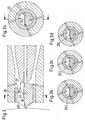
- Fig. 1b is the disadvantageous state of the art ( DE 41 31 059 C2 . US 5,211,001 ) of this latter prior art, as shown in DE 44 31 761 Fig. 5 known, the fibers are not consistent, as in Fig. 1a are guided around the needle, but are guided on both sides of this needle against the inlet mouth of the yarn passage, which allegedly interferes with the binding of the fibers and allegedly can lead to a reduction in the strength of the spun yarn.
- the Figure 1c shows an evolution of the FIG. 1 , 1a or 1a, by the fiber guide surface 4b here, as seen, is helically shaped and the fibers are also guided helically in its course from the nip X to the end E 5 of the helical surface also helically and then further helical to a fiber guide pin, similar fiber guide pin 5 of FIG. 1 , are wound around before the fibers are caught by the rotating air stream and turned into a Y yarn. It can be seen that the rear ends of the fibers f 11 are bent to the mouth portion of the spindle 6 and thereby detected by the rotating air flow and around the front ends, which are already in the center of the fiber flow, wound around thereby the yarn form.
- the Figure 1c equals to FIG. 6 from the DE 19603291 A1 ( US 5647197 ) wherein the characteristics of the spindle 6, the Garn trimlasses 7 and the venting cavity 8 of the FIG. 1 are taken over, while the element e 2, which has a similar function as the needle 5 of FIGS. 1 to 1b , was left that way. From this Figure 1c It can also be seen that the fibers from a helical formation are transferred to the entrance of this spindle.
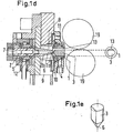
- JP 409106368 U which in contrast to FIG. 1 does not have a needle, but a blunt cone 6 with a flat fiber guide surface, which is a part of the fiber guide channel 13 and whose tip is arranged substantially concentric with the fiber guide 7 course.
- the purpose of this cone is the same as that of the tip 5, namely to produce a so-called false twine core, to prevent the fibers from being twisted wrong, that is, false twist from the tip backwards against the nip of the exit rollers, resulting in truly turning the fibers to form the yarn would at least partially prevent it.
- the object is solved by the characterizing features of claim 1.
- the fiber guiding surface preferably has a fiber discharge edge over and through which the fibers are guided in an essentially flat juxtaposed formation against an inlet mouth of a yarn guide channel.
- the Fig. 1 shows a housing 1 with the housing parts 1 a and 1 b with a built therein nozzle block 2, which contains jet nozzles 3, by means of which an aforementioned vortex flow is generated, and a so-called needle holder 4 with the inserted therein needle. 5
- Fig. 1 As can be seen, the turbulence produces a rightward twist in the direction of the arrow (as viewed in the figure), and accordingly the supplied fibers F are fed in this direction of rotation about the needle 5 against an end face 6a of the so-called spindle 6 and into a yarn passage 7 the spindle 6 is guided.
- the nozzle block 2 there is a relatively large distance between the nozzle block 2 and the end face 6a of the spindle, since there must be room for the needle 5 and its tip at this distance.
- the fibers F are conveyed in a fiber guide channel 13 on the aforementioned fiber guide surface due to a suctioned air flow against the tip 5 of the needle 5.
- the compressed air for the jet nozzles 3 is supplied by means of a Druck Kunststoffverteilraumes 11 the jet nozzles evenly.
- Fig. 1b which the state of the art to the aforementioned Figures 1 and 1a shows that this figure is contrary to Fig. 1a in addition, a needle holder extension 4a ', which protrudes from an end face 4' and the needle 5 includes. That is, the fibers are guided over the entire extension, which arises due to the contour of the needle holder 4, against the inlet of the spindle 6.
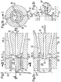
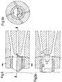
- the invention according to the Fig. 2-2c a fiber delivery edge 29 which is located very close to an inlet port 35 (FIG. Fig. 2a ) of a Garn enclosureskanals 45, which is provided within a so-called spindle 32 and that advantageously with a predetermined distance A ( Fig. 2c ) between the fiber discharge edge 29 and the inlet mouth 35 and a predetermined distance B between an imaginary plane E containing the edge, parallel to a center line 47 of the yarn guide channel 45, and said center line 47.
- the distance A corresponds to a range of 0.1 to 1.0 mm, depending on the type of fiber and average fiber length and corresponding test results.
- the distance B depends on a diameter G of the inlet mouth 35 and, depending on the results of the test, lies within a range of 10 to 40% of the said diameter G.
- the fiber delivery edge has a length D.1 ( Fig. 2a ), which is in a ratio of 1: 5 to the diameter G of Garn entryskanales 45 and from an end face 30 ( Fig. 2 ) of a fiber conveying element 27 and a fiber guiding surface 28 of the element 27 is formed.
- the end face 30 lies, with a height C ( Fig. 2c ), within the range of the diameter G and has an empirically determined distance H between the plane E and the opposite inner wall 48 of the Garn entryskanales 45 on.
- the fiber conveying element 27 is guided in a received in a nozzle block 20 support member 37 and forms with this support member 26 a fiber conveying channel forming space.
- the fiber conveying element 27 has at the entrance to a fiber receiving edge 31, around which the fibers are guided, which are conveyed by a fiber feed roller 39. These fibers are lifted from the conveyor roller by the suction conveyor 39 by means of a suction air flow and conveyed through the fiber conveying channel 26.
- the suction air flow is produced by a jet of air generated in jet nozzles 21 with a blowing direction 38 due to an injector effect.
- jet nozzles are, as with the Figures 2 and 2b shown in a nozzle block 20 on the one hand with an angle ⁇ ( Fig. 2 ) to produce the aforementioned injector action and, on the other hand, at an angle ⁇ ( Fig. 2b ) are inclined to produce an air vortex, which with a direction of rotation 24 on a cone 36 of the Fiber conveying element 27 along and around the spindle front surface 34 (FIG. Fig. 2a ) turns around, as mentioned below, to form a yarn in Garn Adjustskanal 45 of the spindle 32.
- a yarn 46 ( Fig. 2a ) are delivered by the fiber conveying roller 39 fibers F by means of said suction air stream in the fiber conveying channel 26, as mentioned, lifted off the fiber feed roller 39 and on the fiber guide surface 28 in a conveying direction 25 (Fig. Fig. 2 ) is guided against the fiber delivery edge 29. From this discharge edge, leading ends of the fibers are fed through the spindle inlet mouth 35 into the yarn guide channel 45 while the rear ends 49 of these fibers fold down as the trailing ends are exposed and caught by the rotating air flow, so as to further convey the fibers In Garn Replacementskanal 45 a yarn 46 is formed, which has a yarn character similar to the ring yarn.
- the width D.1 ( Fig. 2a ), as shown by dotted lines, expanded on the one hand, to show that this width can be expanded, on the other hand, to illustrate that this extended width may with FIG. 2a shown vortex chamber 22 reduced, if not disturbing changed by the eddy current can not develop in it so that the fiber ends 49 can be detected with the desired energy from the eddy current. This must also be determined by means of empirical experiments.
- the aforementioned yarn formation happens after the beginning of a piecing process of any kind, for example in which a yarn end of an already existing yarn is guided back through the yarn guide channel 45 in the region of the spindle inlet port 35 so far that fibers of this yarn end are opened by the already rotating air flow so far in that new front ends of fibers fed through the fiber guide channel 26 can be grasped by this rotating fiber structure and held therein again by withdrawing the inserted yarn end so that the subsequent back parts of the newly supplied fibers are already around the mouth part of the fiber Garn Entryskanales located front ends can wind around, so that, as a result, the aforementioned yarn can be spun with a substantially predetermined piecing again.
- the procedure has been described with reference to an example in which the front end of a fiber as viewed in the transport direction is integrated in the fiber composite and the rear end of this fiber is free to "fold over".
- the procedure can, however, be analogous in the case of an integrated rear end of the fiber, wherein the front end is free and due to the axial component of the vortex air flow is applied to the spindle front surface 34.
- the fiber parts applied to the spindle front surface 34 then rotate due to the vortex air flow and are thus rotated about the integrated fiber ends.
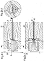
- FIGS. 3 and 3a show a further embodiment of the fiber guide channel 26 of the extent Figures 2-2c as here the fiber guide surface 28.1 with provided with a distance M from the fiber discharge edge 29 remote increase 40 over which the supplied fibers slide before they reach the fiber discharge edge 29.
- the distance M corresponds to a maximum of 50% of the mean fiber length.
- the elevation has a distance N, which is in the range of 10 to 15% of the distance M, compared with a non-increased fiber guide surface.
- the distances M and N are to be determined empirically depending on the fiber type and fiber length.
- slippery fibers are meant those which have weak mutual adhesion and “sticky” fibers which have mutually stronger adhesion.
- the unmarked elements correspond to the elements of the FIGS. 2 to 2c ,
- Another advantage of the increase is that by the movement of the fibers over this point loosening of any dirt within the fiber structure arises, which can be detected by the conveying air flow and conveyed into the open, or in a suction device.
- FIGS. 4 and 4a show a further variant of the fiber guiding surface 28 of FIG. Figures 2-2c ,
- the fiber guide surface at a distance P, from the fiber discharge edge 29 of a maximum of 50% of the average fiber length, a recess 41 with a radius R.1, wherein the lowest point of the recess 41 deeper lies as the edge 29 of the Figures 2-2c ,
- the depression 41 and the radius R.1 are to be determined empirically on the basis of the fiber type and fiber length and the depression 41 serves to prevent (for example short) fibers from sideways moving away, that is to say to be lost as a departure.
- the Figures 5-5b show a further variant of the design of the fiber delivery edge 29 by the end face 30.1 has a provided with a radius R.2 convex curve and thereby the fiber delivery edge 29 receives a width D.2.
- the choice of radius and width is a matter of empirical attempts to optimally adapt to the type of fiber and the fiber length for the yarn design.
- the previously mentioned fluidic optimization of the vortex chamber 22 can also be influenced with measures.
- the unmarked elements correspond to the elements of the FIGS. 2 to 2c .
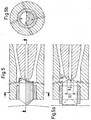
- the Figures 6-6b have a similar idea of variation insofar as here not a convex end face 30.1 but a concave end face 30.2 is provided with a radius R.3 and an edge length of D.3.
- the radius R.3 and the edge length D.3 must be determined empirically according to the fiber length and the fiber type. These measures serve to influence the previously mentioned constriction of the fiber at the inlet mouth.
- the unmarked elements correspond to the elements of the FIGS. 2 to 2c .
- FIGS. 7 and 7a show a variant of Figures 3-3d in which the fiber guide surface here consists of a porous plate 42 made of sintered material, so that compressed air from a located below the porous plate 42 cavity 43 in a very uniform and fine distribution through the porous plate and in the fibers located thereon can flow, so that in a sense a fluidization of the fibers takes place, ie a homogeneous mixing of air and fibers, which is a separation from fiber to fiber and thus an increase in the aforementioned "slipperiness" ie a reduction in the aforementioned adhesion of the fibers caused by the air located between the fibers.
- the fiber guide surface here consists of a porous plate 42 made of sintered material, so that compressed air from a located below the porous plate 42 cavity 43 in a very uniform and fine distribution through the porous plate and in the fibers located thereon can flow, so that in a sense a fluidization of the fibers takes place, ie a homogeneous mixing of
- the compressed air for the cavity 43 is supplied via the compressed air supply 44.
- the pressure in the cavity 43 is to be determined empirically from the porous surface in accordance with the porous plate and the tolerable air outlet velocity, specifically such that the fibers are not lifted off this air flow by a tolerable amount from the fiber guide surface.
- the porous plate is received by the parts 27.1 and 27.2 of the fiber conveying element 27, whereby these parts, because they contain the leading edge and the fiber discharge edge of the fibers, are made of a material which is more resistant to abrasion than a porous plate.
- FIG. 8 shows a nozzle block of FIG Fig. 2.1 in combination with a drafting device 50, consisting of the input rollers 51, the pair of belts 52 with the corresponding rollers and the output roller pair 53, which supplies the fiber strand F to the nozzle block 20.
- the fibers leave the drafting system 50 in a plane containing the nip line of the outfeed roller pair. This plane can be offset from the fiber guide surface 28 in such a way that the fiber structure is deflected at the fiber receiving edge 31 (cf. FIG. 2 or 2a).
- Fig. 9 shows as an alternative to the drafting device, a device in which a sliver 54 dissolved in individual fibers and finally by means of a suction roller 62 as Fiber structure F the nozzle block 20 of the Fig. 2.1 is delivered.
- This device is the subject of a PCT application with the no. PCT / CH 01/00 217 the same applicant to which application is referred, as part of this application.
- An alternative is off US 6,058,693 refer to
- the sliver disintegration device comprises a feed channel 55, in which the sliver 54 is fed to a feed roller 56, wherein the sliver is conveyed by the feed roller 56 further to a needle or toothed roller 61, from which the sliver is dissolved into individual fibers ,
- a feed trough 57 presses the sliver 54 against the feed roll to thereby feed the sliver dosed to the needle roller 61.
- the hinge 58 and the compression spring 59 serve to allow the necessary contact force.
- the needle roller 60 passes the fibers to a suction roller 62.
- a designated T dirt is eliminated.
- the suction roller 62 holds in the A to B, as seen in the direction of rotation, delimited area, with the help of the suction, the fibers to the terminal point K firmly. After this nip point, the fibers are released for forwarding into the fiber guide channel 26. In the channel 26 they are detected by the air stream 25.
- the abovementioned release takes place, for example because the suction on the suction roller 62 is no longer present after the clamping point K, for example because the cover connecting the points A and B (shown in FIG. 9) is no longer provided after the clamping point K.
- the release can be amplified by means of a blown air B 2, which blows through the bores 63 by means of the channel B 2. At this blown air B 2 but can be dispensed with at best.
- the channel B 2 is fed through the channel B 1 with compressed air.
- the fibers leave the suction roll 62 in a plane containing the nip line K.
- This plane can be offset from the fiber guide surface 28 in such a way that the fiber structure is deflected at the fiber receiving edge 31 (cf. Fig. 2 , or 2 a).
- the fiber conveying channel 26 is provided with a fiber guide surface 28, which is executed without twisting (or helix-free) (see the FIG. 1a or 1c).
- the fiber guide surface 28 leads to a fiber delivery edge 29 which is positioned opposite the inlet mouth 35 of the yarn guide channel such that the fiber strand F must contact the edge 29 to enter the inlet port 35. Thereby, a propagation of a yarn twist, upstream of the edge 29, prevented or at least significantly weakened.
- the fiber conveying channel 26 on the one hand on one side of an imaginary, with a view to the Figure 2c seen vertical plane (not shown) and the center line 47 of the yarn channel 45 include.
- the fiber conveying channel 26 is also brought so close to the inlet mouth 35 of the yarn guiding channel 45 that, in combination of the two measures, at least part of the fiber strand F must be deflected in order to get out of the fiber conveying channel 26 into the yarn guiding channel 45 (cf. FIG. 1 a ,.1 c, where, in contrast to the above, a considerable distance between the end of the fiber guide channel and the spindle is present to allow the provision of the needle 5 in the space).
- the fiber delivery edge 29 of the fiber delivery channel 26 is in a parallel plane E (to the former, including the center line 47).
- Figure 2c which is provided opposite the first-mentioned plane with a predetermined distance B.
- FIGS. 8 and 9 also show that the fibers which leave the fiber conveying channel 26 during operation come directly (or directly) into the area (space 22, FIG. FIG. 2 ) enter, in which the vortex flow is present. This also makes a difference from the arrangement according to the FIG. 1 because in this the latter arrangement, a distance between the end of the fiber guide channel 13 and the plane in which the outlet openings of the blowing nozzles 3 are located.
Description
Die Erfindung betrifft eine Vorrichtung zur Herstellung eines gesponnenen Fadens aus einem Faserverband gemäss dem Oberbegriff des Anspruchs 1.The invention relates to a device for producing a spun yarn from a fiber structure according to the preamble of claim 1.
Eine solche Vorrichtung ist aus der
Die sogenannte Nadel und deren Spitze, um welche die Fasern geführt werden befindet sich nahe oder in der Eingangsmündung 6c des Garndurchlasses 7 und dient als sogenannter falscher Garnkern, um möglichst zu verhindern, beziehungsweise zu reduzieren, dass durch die Fasern im Faserbündeldurchlass ein die Fasern unzulässig hoher, zusammenschnürender Falschdrall der Fasern entsteht, welcher die Garnbildung mindestens stören wenn nicht sogar verhindern würde.The so-called needle and its tip, about which the fibers are guided, is located near or in the
In der
Die
Die
Ein weiterer Stand der Technik vom selben Anmelder ist in der
Es war deshalb Aufgabe, ein Verfahren bzw. eine Vorrichtung zu finden, in welcher die Fasern eine Faserführung erfahren, mittels welcher die Fasern derart vom erzeugten Luftwirbel erfasst werden können, dass ein gleichmässiges und festes Garn erzeugt werden kann.It was therefore an object to find a method and an apparatus in which the fibers undergo a fiber guide, by means of which the fibers can be detected by the air vortex generated in such a way that a uniform and strong yarn can be produced.
Die Aufgabe wird durch die kennzeichnenden Merkmale des Anspruchs 1 gelöst. Die Faserführungsfläche weist bevorzugt eine Faserabgabekante auf, über und durch welche die Fasern in einer im wesentlichen flach nebeneinander liegenden Formation gegen eine Einlassmündung eines Garnführungskanales geführt werden.The object is solved by the characterizing features of claim 1. The fiber guiding surface preferably has a fiber discharge edge over and through which the fibers are guided in an essentially flat juxtaposed formation against an inlet mouth of a yarn guide channel.
Weitere vorteilhafte Ausführungsformen sind in den weiteren abhängigen Ansprüchen aufgeführt.Further advantageous embodiments are listed in the further dependent claims.
Im folgenden wird die Erfindung anhand von lediglich Ausführungswege darstellenden Zeichnungen näher erläutert.In the following the invention will be explained in more detail with reference to drawings showing only execution paths.
Es zeigt:
- Fig. 1-1c
- Figuren aus der
DE 44 31 761 C2 Fig. 1b der Vorrichtung derDE 41 31 059 C2 Figur 1c der Vorrichtung derDE 19 60 32 91 A1 JP3 -10 63 68 (2 - Fig. 1d Und 1e
- Figuren aus der
JP3 -10 63 68 (2 - Fig. 2
- eine erste Ausführung der Erfindung im wesentlichen gemäss den Schnittlinien I-I (
Fig. 2b ) wobei ein mittleres Element nicht geschnitten dargestellt ist - Fig. 2a
- ein Schnitt gemäss den Schnittlinien II-II von
Fig. 2 - Fig. 2b
- ein Querschnitt gemäss den Schnittlinien III-III von
Fig. 2 - Fig. 2c
- ein Ausschnitt aus
Fig. 2 , vergrössert dargestellt - Fig. 2.1
- die gleiche Ausführung wie
Fig. 2 , wobei zusätzlich der Faser- bzw. Garnfluss auch gezeigt ist - Fig. 2a.1
- entspricht der
Fig.2a , wobei zusätzlich der Faser- bzw. Garnfluss und eine mögliche Modifikation der Faserabgabekante auch gezeigt sind - Fig. 2b.1
- entspricht der
Fig.2b , wobei zusätzlich der Faser- bzw. Garnfluss auch gezeigt ist - Fig. 3
- eine zweite Ausführung der Erfindung im wesentlichen gemäss den Schnittlinien I-I von
Fig. 3a - Fig. 3a
- einen Querschnitt gemäss der Schnittlinien III-III der
Figur 3 - Fig. 3b
- einen Querschnitt entsprechend der
Fig 3a durch eine erste Variante der zweiten Ausführung - Fig. 3c
- einen Querschnitt entsprechend der
Fig 3a durch eine zweite Variante der zweiten Ausführung - Fig. 3c
- einen Querschnitt entsprechend der
Fig 3a durch eine dritte Variante der zweiten Ausführung - Fig. 4
- eine dritte Ausführung der Erfindung im wesentlichen gemäss den Schnittlinien I-I von
Fig. 4a - Fig. 4a
- einen Querschnitt gemäss der Schnittlinien III-III der
Figur 4 - Fig. 5-5b
- eine weitere Variante der Erfindung gemäss der
Figuren 2-2b - Fig. 6-6b
- noch eine Variante der Erfindung gemäss der
Figuren 2-2b - Fig. 7
- eine weitere Variante der Erfindung gemäss der
Figur 3 , - Fig. 7a
- einen Querschnitt gemäss der Schnittlinien IV-
IV der Figur 7 - Fig 8
- eine Darstellung eines Streckwerkes als Faserzufuhr in das Element der
Fig. 2.1 - Fig. 9
- eine Darstellung einer Faserauflösevorrichtung als Faserzufuhr in das Element der
Fig. 2.1
- Fig. 1-1c
- Figures from the
DE 44 31 761 C2Fig. 1b the device ofDE 41 31 059 C2Figure 1c the device ofDE 19 60 32 91 A1JP3 -10 63 68 (2 - Fig. 1d and 1e
- Figures from the
JP3 -10 63 68 (2 - Fig. 2
- a first embodiment of the invention substantially according to the section lines II (
Fig. 2b ) wherein a central element is not shown cut - Fig. 2a
- a section according to the section lines II-II of
Fig. 2 - Fig. 2b
- a cross section according to the section lines III-III of
Fig. 2 - Fig. 2c
- a section from
Fig. 2 , enlarged - Fig. 2.1
- the same design as
Fig. 2 , wherein additionally the fiber or yarn flow is also shown - Fig. 2a.1
- equals to
2a In addition, the fiber or yarn flow and a possible modification of the fiber delivery edge are also shown - Fig. 2b.1
- equals to
2b , wherein additionally the fiber or yarn flow is also shown - Fig. 3
- a second embodiment of the invention substantially according to the section lines II of
Fig. 3a - Fig. 3a
- a cross section according to the section lines III-III of
FIG. 3 - Fig. 3b
- a cross section corresponding to the
Fig. 3a by a first variant of the second embodiment - Fig. 3c
- a cross section corresponding to the
Fig. 3a by a second variant of the second embodiment - Fig. 3c
- a cross section corresponding to the
Fig. 3a by a third variant of the second embodiment - Fig. 4
- a third embodiment of the invention substantially according to the section lines II of
Fig. 4a - Fig. 4a
- a cross section according to the section lines III-III of
FIG. 4 - Fig. 5-5b
- a further variant of the invention according to the
Figures 2-2b - Fig. 6-6b
- another variant of the invention according to
Figures 2-2b - Fig. 7
- a further variant of the invention according to the
FIG. 3 . - Fig. 7a
- a cross section according to the section lines IV-IV of
FIG. 7 - Fig. 8
- a representation of a drafting system as a fiber supply in the element of
Fig. 2.1 - Fig. 9
- a representation of a Faserauflösevorrichtung as fiber supply to the element of
Fig. 2.1
Die
Wie aus
Die Fasern F werden in einem Faserführungskanal 13 auf der vorgenannten Faserführungsfläche aufgrund eines eingesaugten Luftstromes gegen die Spitze 5 der Nadel 5 gefördert.The fibers F are conveyed in a
Der eingesaugte Luftstrom erfolgt aufgrund einer Injektorwirkung der Strahldüsen 3, welche derart vorgesehen sind, dass einerseits der genannte Luftwirbel erzeugt aber andererseits auch Luft durch den Faserförderkänal 13 gesaugt wird.The sucked air flow takes place due to an injector effect of the
Diese Luft entweicht einem Konusteil 6b der Spindel 6 entlang durch einen Entlüftungshohlraum 8 in einen Luftauslass 10.This air escapes a
Die Druckluft für die Strahldüsen 3 wird mittels eines Druckluftverteilraumes 11 den Strahldüsen gleichmässig zugeführt.The compressed air for the
Die
Die
Der Nachteil dieser Vorrichtungen besteht in der ungewissen Faserführung im grossen Abstand von der Stirnseite des Nadelhalters 4 bis zur Einlassmündung 6c in der Stirnseite 6a der Spindel 6 sowie durch die Führung der Fasern an oder um die Nadel 5 beziehungsweise den Konus 6 der
The disadvantage of these devices is the uncertain fiber guidance at a large distance from the end face of the needle holder 4 to the
Um diese Nachteile zu beheben weist die Erfindung gemäss den
Dabei entspricht der Abstand A je nach Faserart und mittlerer Faserlänge und entsprechenden Versuchsresultaten einem Bereich von 0,1 bis 1,0 mm. Der Abstand B hängt von einem Durchmesser G der Einlassmündung 35 ab und liegt, je nach Versuchsresultaten, innerhalb eines Bereichs von 10 bis 40 % des genannten Durchmessers G.The distance A corresponds to a range of 0.1 to 1.0 mm, depending on the type of fiber and average fiber length and corresponding test results. The distance B depends on a diameter G of the inlet mouth 35 and, depending on the results of the test, lies within a range of 10 to 40% of the said diameter G.
Im weiteren weist die Faserabgabekante eine Länge D.1 (
Das Faserförderelement 27 ist in einem in einem Düsenblock 20 aufgenommenen Tragelement 37 geführt und bildet mit diesem Tragelement einen Faserförderkanal 26 bildenden Freiraum.The
Das Faserförderelement 27 weist am Eingang eine Faseraufnahmekante 31 auf, um welche die Fasern geführt werden, die von einer Faserförderwalze 39 zugefördert werden. Diese Fasern werden von der Faserförderwalze 39 mittels eines Saugluftstromes von der Förderwalze abgehoben und durch den Faserförderkanal 26 gefördert. Der Saugluftstrom entsteht durch einen in Strahldüsen 21 mit einer Blasrichtung 38 erzeugten Luftstrom, aufgrund einer Injektorwirkung.The
Diese Strahldüsen sind, wie mit den
Der von den Düsen 21 in einer Wirbelkammer 22 erzeugte Luftstrom entweicht einem Spindelkonus 33 entlang, durch einen sich µm die Spindel 32 gebildeten Entlüftungskanal 23 in die Atmosphäre oder in eine Saugeinrichtung.The air flow generated by the
Zur Bildung eines Garnes 46 (
Dieser Vorgang ist mit den
In dieser Figur ist die Breite D.1 (
Die vorerwähnte Garnbildung geschieht nach Beginn eines Anspinnvorganges irgend welcher Art, beispielsweise in welchem ein Garnende eines bereits bestehenden Garnes zurück durch den Garnführungskanal 45 in den Bereich der Spindeleinlassmündung 35 so weit geführt wird, dass Fasern dieses Garnendes vom sich bereits drehenden Luftstrom so weit geöffnet werden, dass neu durch den Faserführungskanal 26 zugeführte vordere Enden von Fasern von diesem sich drehenden Faserverband erfasst werden können und durch erneutes Abziehen des eingeführten Garnendes darin gehalten werden können, so dass die nachfolgenden hinteren Teile der neu zugelieferten Fasern sich um die sich bereits im Mündungsteil des Garnführungskanales befindlichen vorderen Enden herumwinden können, so dass in der Folge das vorerwähnte Garn mit einem im wesentlichen vorgegebenen Ansetzer erneut gesponnen werden kann.The aforementioned yarn formation happens after the beginning of a piecing process of any kind, for example in which a yarn end of an already existing yarn is guided back through the
Der Ablauf wurde beschrieben anhand eines Beispieles, in welchem das vordere Ende einer Faser in der Transportrichtung betrachtet im Faserverbund eingebunden ist und das hintere Ende dieser Faser zum "Umklappen" frei ist bzw. wird. Das Vorgehen kann aber analog ablaufen im Falle eines eingebundenen hinteren Endes der Faser, wobei das vordere Ende frei ist und aufgrund des axialen Komponente des Wirbelluftstromes an der Spindelfrontfläche 34 angelegt wird. Die an der Spindelfrontfläche 34 angelegten Faserteile rotieren dann aufgrund des Wirbelluftstromes und werden somit um die eingebundenen Faserenden gedreht.The procedure has been described with reference to an example in which the front end of a fiber as viewed in the transport direction is integrated in the fiber composite and the rear end of this fiber is free to "fold over". The procedure can, however, be analogous in the case of an integrated rear end of the fiber, wherein the front end is free and due to the axial component of the vortex air flow is applied to the spindle front surface 34. The fiber parts applied to the spindle front surface 34 then rotate due to the vortex air flow and are thus rotated about the integrated fiber ends.
Die
Die Erhöhung weist gegenüber einer nicht erhöhten Faserführungfläche einen Abstand N auf, welcher im Bereich von 10 bis 15 % des Abstandes M liegt.The elevation has a distance N, which is in the range of 10 to 15% of the distance M, compared with a non-increased fiber guide surface.
Die Abstände M und N sind je nach Faserart und Faserlänge empirisch zu ermitteln.The distances M and N are to be determined empirically depending on the fiber type and fiber length.
Diese Erhöhung 40 kann die mit den
Diese Formen dienen der unterschiedlichen Faserführung auf der Faserführungsfläche 28.1 - 28.4 und sind je nach Faserart und Faserlänge empirisch zu ermitteln.
Dabei versteht man unter "schlüpfrigen" Fasern solche, welche eine schwache gegenseitige Adhäsion und unter "klebrige" Fasern solche, welche eine gegenseitig stärkere Adhäsion aufweisen.
Die nicht gekennzeichneten Elemente entsprechen den Elementen der
By "slippery" fibers is meant those which have weak mutual adhesion and "sticky" fibers which have mutually stronger adhesion.
The unmarked elements correspond to the elements of the
Ein weiterer Vorteil der Erhöhung besteht darin, dass durch die Bewegung der Fasern über diese Stelle eine Lockerung von eventuellen Schmutzteilen innerhalb des Faserverbandes entsteht, welche durch den Förderluftstrom erfasst und ins Freie, bzw. in eine Saugvorrichtung gefördert werden können.Another advantage of the increase is that by the movement of the fibers over this point loosening of any dirt within the fiber structure arises, which can be detected by the conveying air flow and conveyed into the open, or in a suction device.
Die
Auch diese Variante kann wie mit
Die nicht gekennzeichneten Elemente entsprechen den Elementen der
The unmarked elements correspond to the elements of the
Die
Die nicht gekennzeichneten Elemente entsprechen den Elementen der
Die
Die nicht gekennzeichneten Elemente entsprechen den Elementen der
Die
Durch diese Trennung wird allfälliger Schmutz besser losgelöst und freigesetzt, so dass dieser Schmutz beim Übergang über die Zwischenerhöhung 40 besser vom Saugluftstrom erfasst werden kann. Die Druckluft für den Hohlraum 43 wird über die Druckluftzufuhr 44 zugeführt.Through this separation, any dirt is better detached and released, so that this dirt during transition via the
Der Druck im Hohlraum 43 ist entsprechend der porösen Platte und der tolerierbaren Luftaustrittsgeschwindigkeit aus der porösen Oberfläche empirisch zu ermitteln und zwar derart, dass die Fasern von diesem Luftstrom nicht über ein tolerierbares Mass von der Faserführungsfläche abgehoben werden.The pressure in the
Die poröse Platte wird durch die Teile 27.1 und 27.2 des Faserförderelementes 27 aufgenommen, wobei durch diese Teile, da sie die Einlaufkante und die Faserabgabekante der Fasern enthalten, aus einem Material gefertigt sind, welches abriebfester ist als eine poröse Platte.The porous plate is received by the parts 27.1 and 27.2 of the
Die Fig. 8 zeigt einen Düsenblock der
Die Fig. 9 zeigt als Alternative zum Streckwerk eine Vorrichtung, in welcher ein Faserband 54 in Einzelfasern aufgelöst und letztlich mittels einer Saugwalze 62 als Faserverband F dem Düsenblock 20 der
Die Faserband-Auflösevorrichtung gemäss der Figur 9 umfasst einen Speisekanal 55, in welchem das Faserband 54 einer Speisewalze 56 zugeliefert wird, wobei das Faserband von der Speisewalze 56 weiter an eine Nadel- oder Zahnwalze 61 gefördert wird, von welcher das Faserband in Einzelfasern aufgelöst wird. Eine Speisemulde 57 presst das Faserband 54 gegen die Speisewalze, um dadurch das Faserband dosiert der Nadel-, beziehungsweise Zahnwalze 61, zuzuspeisen. Dabei dienen das Scharnier 58 und die Druckfeder 59 dazu, die notwendige Anpresskraft zu ermöglichen.The sliver disintegration device according to FIG. 9 comprises a feed channel 55, in which the sliver 54 is fed to a feed roller 56, wherein the sliver is conveyed by the feed roller 56 further to a needle or toothed roller 61, from which the sliver is dissolved into individual fibers , A feed trough 57 presses the sliver 54 against the feed roll to thereby feed the sliver dosed to the needle roller 61. The hinge 58 and the compression spring 59 serve to allow the necessary contact force.
Im weiteren übergibt die Nadelwalze 60 die Fasern an eine Saugwalze 62. Dabei wird ein mit T gekennzeichneter Schmutz ausgeschieden.In addition, the
Die Saugwalze 62 hält in dem von A bis B, in Drehrichtung gesehen, abgegrenzten Bereich, mit Hilfe der Saugkraft die Fasern bis zum Klemmpunkt K fest. Nach diesem Klemmpunkt werden die Fasern zum Weiterleiten in den Faserführungskanal 26 freigegeben. Im Kanal 26 werden sie vom Luftstrom 25 erfasst. Die vorgenannte Freigabe erfolgt, z.B: weil die Saugwirkung auf der Saugwalze 62 nach dem Klemmpunkt K nicht mehr vorhanden ist, beispielsweise weil die die Punkte A und B verbindende Abdeckung (in der Figur 9 gezeigt) nach dem Klemmpunkt K nicht mehr vorgesehen ist. Die Freigabe kann aber mittels einer Blasluft B 2 verstärkt werden, welche mittels des Kanales B 2 durch die Bohrungen 63 bläst. Auf diese Blasluft B 2 kann aber allenfalls verzichtet werden. Der Kanal B 2 wird durch den Kanal B 1 mit Druckluft beschickt.The suction roller 62 holds in the A to B, as seen in the direction of rotation, delimited area, with the help of the suction, the fibers to the terminal point K firmly. After this nip point, the fibers are released for forwarding into the
Die Fasern verlassen die Saugwalze 62 in einer Ebene, welche die Klemmlinie K enthält. Diese Ebene kann derart gegenüber der Faserführungsfläche 28 versetzt werden, dass der Faserverband an der Faseraufnahmekante 31 umgelenkt wird (vgl.
Was das Streckwerk der Fig. 8 betrifft, handelt es sich um ein an sich allgemein bekanntes Streckwerksystem, weshalb nicht weiter darauf eingegangen wird.As regards the drafting system of FIG. 8, it is a drafting system which is generally known per se, for which reason it will not be discussed further.
Aus den Figuren 8 und 9 ist ersichtlich, dass der Faserförderkanal 26 mit einer Faserführungsfläche 28 versehen ist, welche ohne Tordierung (bzw. wendelfrei) ausgeführt ist (vgl der
Aus den gleichen Figuren ist ersichtlich, dass sich der Faserförderkanal 26 zum einen gänzlich auf einer Seite einer gedachten, mit Blick auf die
In der bevorzugten Anordnung (Figur 8 und 9) ist die Faserabgabekante 29 des Faserförderkanales 26 in einer zur erstgenannten, die Mittellinie 47 beinhaltenden, parallelen Ebene E (
Die Figuren 8 und 9 zeigen auch, dass die Fasern, welche im Betrieb den Faserförderkanal 26 verlassen, direkt (bzw. unmittelbar) in den Bereich (Raum 22,
- 11
- Gehäusecasing
- 1a, 1b1a, 1b
- Gehäuseteilehousing parts
- 22
- Düsenblocknozzle block
- 33
- Strahldüsenjets
- 44
- Nadelhalterneedle holder
- 4'4 '
- Stirnseite von 4Front side of 4
- 4a'4a '
- NadelhalterfortsatzNeedle holder extension
- 4b4b
- FaserführungsflächeFiber guide surface
- 4c4c
- FaserabgabekanteFiber delivery edge
- 55
- Nadelneedle
- 66
- Spindelspindle
- 6a6a
- Stirnseitefront
- 6b6b
- Konusteilconical part
- 6c6c
- Eingangsmündung von 7Entrance estuary of 7
- 77
- Garndurchlassyarn passage
- 88th
- Entlüftungshohlraumventing cavity
- 1010
- LuftdurchlassAir passage
- 1111
- DruckluftverteilraumDruckluftverteilraum
- 1212
- --
- 1313
- FaserführungskanalFiber guide channel
- 2020
- Düsenblocknozzle block
- 2121
- Strahldüsenjets
- 2222
- Wirbelkammerswirl chamber
- 2323
- Entlüftungskanalvent channel
- 2424
- Drehrichtung des LuftwirbelsDirection of rotation of the air vortex
- 2525
- Förderrichtung der angesaugten LuftConveying direction of the sucked air
- 2626
- FaserförderkanalFiber conveying channel
- 2727
- FaserförderelementFiber conveying element
- 27.1+27.227.1 + 27.2
- Teile von 27Parts of 27
- 28, 28.1, 28.2, 28.3, 28.4, 28.528, 28.1, 28.2, 28.3, 28.4, 28.5
- FaserführungsflächeFiber guide surface
- 2929
- FaserabgabekanteFiber delivery edge
- 30, 30.2, 30.230, 30.2, 30.2
- Stirnflächeface
- 3131
- FaseraufnahmekanteFiber take-up edge
- 3232
- Spindelspindle
- 3333
- Spindelkonusspindle taper
- 3434
- SpindelfrontflächeSpindle front surface
- 3535
- SpindeleinlassmündungSpindle inlet port
- 3636
- Konus von 27Cone of 27
- 3737
- Tragelement für 27Support element for 27
- 3838
- Mittellinie von 21 und BlasrichtungCenterline of 21 and blowing direction
- 3939
- FaserförderwalzeFiber conveying roller
- 4040
- ZwischenhöhungskanteZwischenhöhungskante
- 4141
- Vertiefungdeepening
- 4242
- Poröse Platte (Intermaterial)Porous plate (Intermaterial)
- 4343
- Hohlraumcavity
- 4444
- DruckluftzufuhrCompressed air supply
- 4545
- Garnführungskanalyarn guide
- 4646
- Garnyarn
- 4747
- Mittelliniecenter line
- 4848
- Innenwand von 45Inside wall of 45
- 4949
- hintere Faserendenrear fiber ends
- 5050
- Streckwerkdrafting system
- 5151
- EingangswalzenpaarPair of input rollers
- 5252
- Riemchen-WalzenpaarStrappy pair of rollers
- 5353
- AusgangswalzenpaarRoller pair
- 5454
- Faserbandsliver
- 5555
- Speisekanalfeeding channel
- 5656
- Speisewalzefeed roll
- 5757
- Speisemuldefeed trough
- 5858
- Scharnier von 4Hinge of 4
- 5959
- Druckfeder für 4Compression spring for 4
- 6060
- Auflösewalzeopening roller
- 6161
- Nadeln oder ZähneNeedles or teeth
- 6262
- Saugwalzesuction roll
- 6363
- Bohrungendrilling
- 6464
- Andrückwalzepressure roller
- 6565
- Abzugswalzenoff rolls
Claims (15)
- A device for producing a spun yarn from a fiber strand comprising a fiber delivery channel (26) with a fiber guide surface (28) for guiding the fibers of the fiber strand into an intake mouth (35) of a yarn guide channel (45) and a fluid device for generating an eddy current around the intake mouth (35) of the yarn guide channel (45), wherein the yarn guide channel (45) has a middle line (47) at least in the region of the intake mouth (35), wherein the fiber guide surface (28) has a fiber dispensing edge (29) and the fiber delivery channel (26) is situated entirely on one side of an imaginary plane, which includes the middle line (47) of the yarn guide channel (45),
characterized in that
the fiber delivery channel (26) passes close by the intake mouth (35) of the yarn guide channel (45), so that during operation, the fibers leaving the fiber delivery channel (26) enter the region of the eddy current directly, and at least a portion of the fiber strand is deflected on the fiber dispensing edge (29) to arrive from the fiber delivery channel (26) into the yarn guide channel (45), wherein the propagation of the yarn twist upstream from the fiber-dispensing edge (29) is thereby prevented or is at least substantially diminished. - The device according to claim 1, characterized in that the fiber-dispensing edge (29) is designed so that the fibers (F) are guided over and through the fiber dispensing edge (29) in a formation situated essentially flatly side by side toward the intake mouth (35) of the yarn guide channel (45).
- The device according to claim 1 or 2, characterized in that the fiber-dispensing edge (29) is at a predetermined distance (A) from the intake mouth (35) as seen in the direction of conveyance of the fibers and is at a predetermined distance (B) from a middle line (47) of the yarn guide channel (45), as seen perpendicular to the middle line (47).
- The device according to claim 1 or 2, characterized in that at least one elevation (40) is provided upstream from the aforementioned dispensing edge (29) as seen in the direction of conveyance of the fibers, the shape of this elevation as seen in cross section being1) a straight line,2) a concave curvature or3) a convex curvature or4) a combination of a concave curvature and a convex curvature,to influence the fiber spacings in the fiber flow in accordance with the aforementioned shape.
- The device according to claim 4, characterized in that the elevation (40) yields an excess height (N) for the fibers, such that any particles of dirt being deflected out of the fibers can be deflected away and picked up by the intake air stream.
- The device according to claim 4, characterized in that at least in the region in front of the elevation (4) and/or in front of the fiber dispensing edge (29), the fiber guide surface (28) and the material forming the guide surface are air permeable, so that compressed air can flow through this material and through the guide surface as well as through the fibers, such that the separation of particles of dirt from the fibers, on the one hand, and the alignment/separation of the fibers, on the other hand, are influenced and/or improved in accordance with the shape of the fiber guide surface.
- The device according to claim 6, characterized in that the fiber guide surface and the aforementioned material are air permeable with such fine pores that there is a fluidization of the fibers with air.
- The device according to claim 7, characterized in that said material and said air pressure are such that the amount and velocity of the fluidized air are taken over by the intake air stream in the fiber delivery channel (26) without lifting the fibers up from the edges (40, 29).
- The device according to claim 1 or 2, characterized in that an end face (30, 30.1, 30.2), which is essentially perpendicular to said midline and which jointly has an influence on the dispensing edge (29), has a shape that plays a role in determining the fiber guide on the dispensing edge (29).
- The device according to claim 9, characterized in that the end face (30) has a concave or convex or corrugated shape.
- The device according to claim 1, characterized in that the fiber delivery channel (26) is provided with a coil-free fiber guide surface (28).
- The device according to claim 1, characterized in that the fiber delivery channel is situated entirely on a side of a second imaginary plane facing away from the plane mentioned first, this second imaginary plane being situated opposite the plane mentioned first and in parallel at a predefined distance.
- The device according to claim 3, characterized in that the distance (A) is in the range of 0.1 to 1.0 mm from the intake mouth (35) and the distance (B) from the midline (47) of the intake mouth is in the range of 10% to 40% of the diameter (G) of the intake mouth.
- The device according to claim 5, characterized in that an elevation (40) is provided at a distance (M) from the fiber-dispensing edge (29) and the distance (M) corresponds to max. 50% of the average fiber length.
- The device according to claim 14, characterized in that the elevation (40) is at a distance N from a fiber guide surface which is not elevated, this distance N being in the range of 10 to 15% of the distance M.
Applications Claiming Priority (3)
| Application Number | Priority Date | Filing Date | Title |
|---|---|---|---|
| CH18452000 | 2000-09-22 | ||
| CH18452000 | 2000-09-22 | ||
| PCT/CH2001/000569 WO2002024993A2 (en) | 2000-09-22 | 2001-09-19 | Spinning device |
Publications (3)
| Publication Number | Publication Date |
|---|---|
| EP1332248A2 EP1332248A2 (en) | 2003-08-06 |
| EP1332248B1 EP1332248B1 (en) | 2016-04-13 |
| EP1332248B9 true EP1332248B9 (en) | 2016-07-13 |
Family
ID=4566483
Family Applications (1)
| Application Number | Title | Priority Date | Filing Date |
|---|---|---|---|
| EP01962535.9A Expired - Lifetime EP1332248B9 (en) | 2000-09-22 | 2001-09-19 | Spinning device |
Country Status (6)
| Country | Link |
|---|---|
| US (1) | US7059110B2 (en) |
| EP (1) | EP1332248B9 (en) |
| JP (1) | JP4921685B2 (en) |
| CN (1) | CN1298903C (en) |
| AU (1) | AU2001283761A1 (en) |
| WO (1) | WO2002024993A2 (en) |
Families Citing this family (20)
| Publication number | Priority date | Publication date | Assignee | Title |
|---|---|---|---|---|
| EP1205588B1 (en) | 2000-11-08 | 2004-12-15 | Maschinenfabrik Rieter Ag | Control of several spinning stationes in a spinning machine |
| DE50310137D1 (en) * | 2002-02-12 | 2008-08-28 | Rieter Ag Maschf | Textile processing machine with a fiber conveying channel and a fiber guiding surface |
| CN1878895B (en) * | 2003-11-11 | 2010-09-01 | 里特机械公司 | Spinning post with fibre guidance element |
| EP1584715A1 (en) * | 2004-04-07 | 2005-10-12 | Maschinenfabrik Rieter Ag | Method of manufacturing a yarn in an air-vortex spinning machine |
| WO2006063482A1 (en) * | 2004-12-15 | 2006-06-22 | Maschinenfabrik Rieter Ag | Spin box comprising a replaceable spindle |
| DE102008006379A1 (en) * | 2008-01-29 | 2009-07-30 | Oerlikon Textile Gmbh & Co. Kg | Air-jet spinning device for use in production of yarn, has cladding gap downstream to plane, in which air flow initially withdrawing from nozzles impinges housing part surface, where gap width suddenly increases and is in specific range |
| DE102009034206A1 (en) * | 2009-07-17 | 2011-01-27 | Maschinenfabrik Rieter Ag | Component for an air jet spinning device |
| JP5515934B2 (en) * | 2010-03-25 | 2014-06-11 | 村田機械株式会社 | Pneumatic spinning device and spinning machine |
| JP5549551B2 (en) * | 2010-11-10 | 2014-07-16 | 村田機械株式会社 | Spinning method using pneumatic spinning device and pneumatic spinning device |
| CH704780A1 (en) * | 2011-04-13 | 2012-10-15 | Rieter Ag Maschf | Roving machine for manufacturing a roving. |
| DE102012110315A1 (en) * | 2012-10-29 | 2014-04-30 | Maschinenfabrik Rieter Ag | Garnbildungselement for an air-spinning machine with an insert and spinneret equipped therewith |
| CN102926054B (en) * | 2012-11-09 | 2015-04-22 | 东华大学 | Air injection vortex spinning device with pumping component |
| CH709953A1 (en) * | 2014-07-30 | 2016-02-15 | Rieter Ag Maschf | Method for operating an air spinning machine. |
| CN105088439A (en) * | 2015-09-25 | 2015-11-25 | 郑世浦 | Dust-proof airflow twisting device with filter screen for spinning |
| CN105113065A (en) * | 2015-09-25 | 2015-12-02 | 俞升洋 | Textile airflow twisting device with heat dissipation function |
| CN105088435A (en) * | 2015-09-25 | 2015-11-25 | 杨田花 | Airflow bunching device for spinning |
| CH712409A1 (en) * | 2016-04-29 | 2017-10-31 | Rieter Ag Maschf | Air-jet spinning machine and method for producing a yarn. |
| ITUA20163011A1 (en) * | 2016-04-29 | 2017-10-29 | Savio Macch Tessili Spa | AIR-JET TYPE SPINNING DEVICE |
| ITUA20163006A1 (en) * | 2016-04-29 | 2017-10-29 | Savio Macch Tessili Spa | AIR-JET TYPE SPINNING DEVICE |
| JP2021042508A (en) | 2019-09-13 | 2021-03-18 | 村田機械株式会社 | Air spinning apparatus and air spinning machine |
Family Cites Families (25)
| Publication number | Priority date | Publication date | Assignee | Title |
|---|---|---|---|---|
| JPS59112036A (en) * | 1982-12-13 | 1984-06-28 | Toyoda Autom Loom Works Ltd | False twist nozzle for spinning |
| JPS6385123A (en) * | 1986-09-22 | 1988-04-15 | Murata Mach Ltd | Production of spun yarn and apparatus therefor |
| JP2897260B2 (en) * | 1989-07-14 | 1999-05-31 | 株式会社デンソー | Brake pressure control device |
| JPH0350059U (en) * | 1989-09-19 | 1991-05-15 | ||
| JPH03106368A (en) * | 1989-09-20 | 1991-05-02 | Matsushita Electric Ind Co Ltd | Bathtub with bubble generating unit |
| DE4036119C2 (en) * | 1989-11-14 | 1994-07-07 | Murata Machinery Ltd | Device for producing spun threads |
| JPH03106368U (en) * | 1990-02-15 | 1991-11-01 | ||
| JPH0465535A (en) * | 1990-07-04 | 1992-03-02 | Murata Mach Ltd | Spinning machine |
| JPH069027Y2 (en) * | 1990-09-18 | 1994-03-09 | 村田機械株式会社 | Spinning equipment |
| JPH0674530B2 (en) * | 1991-07-30 | 1994-09-21 | 村田機械株式会社 | Spinning equipment |
| JPH0748673Y2 (en) * | 1992-02-19 | 1995-11-08 | 村田機械株式会社 | Spinning equipment |
| JPH06108322A (en) * | 1992-09-24 | 1994-04-19 | Murata Mach Ltd | Apparatus for spinning |
| JPH0770833A (en) * | 1993-09-02 | 1995-03-14 | Murata Mach Ltd | Air fine spinning device |
| JP2697575B2 (en) | 1993-09-08 | 1998-01-14 | 村田機械株式会社 | Spinning equipment |
| JPH07173727A (en) * | 1993-12-20 | 1995-07-11 | Murata Mach Ltd | Air-spinning device |
| JPH07197330A (en) * | 1993-12-28 | 1995-08-01 | Murata Mach Ltd | Pneumatic spinning apparatus |
| JP2708000B2 (en) * | 1995-02-10 | 1998-02-04 | 村田機械株式会社 | Spinning equipment |
| JP2773670B2 (en) * | 1995-02-10 | 1998-07-09 | 村田機械株式会社 | Spinning equipment |
| JP2930010B2 (en) * | 1996-05-16 | 1999-08-03 | 村田機械株式会社 | Spinning machine piecing method and apparatus |
| JPH10204731A (en) * | 1997-01-16 | 1998-08-04 | Murata Mach Ltd | Spinning apparatus |
| DE19746602B4 (en) * | 1997-10-22 | 2008-05-29 | Maschinenfabrik Rieter Ag | spinning process |
| JP3123517B2 (en) * | 1998-08-18 | 2001-01-15 | 村田機械株式会社 | Spinning nozzle member |
| EP0990719B1 (en) * | 1998-10-02 | 2003-05-28 | W. SCHLAFHORST AG & CO. | Spinning device |
| DE19926492A1 (en) * | 1998-10-02 | 2000-04-06 | Schlafhorst & Co W | Spinning device |
| DE50310137D1 (en) * | 2002-02-12 | 2008-08-28 | Rieter Ag Maschf | Textile processing machine with a fiber conveying channel and a fiber guiding surface |
-
2001
- 2001-09-19 EP EP01962535.9A patent/EP1332248B9/en not_active Expired - Lifetime
- 2001-09-19 AU AU2001283761A patent/AU2001283761A1/en not_active Abandoned
- 2001-09-19 WO PCT/CH2001/000569 patent/WO2002024993A2/en active Application Filing
- 2001-09-19 JP JP2002529580A patent/JP4921685B2/en not_active Expired - Fee Related
- 2001-09-19 CN CNB018193692A patent/CN1298903C/en not_active Expired - Fee Related
- 2001-09-19 US US10/381,156 patent/US7059110B2/en not_active Expired - Lifetime
Also Published As
| Publication number | Publication date |
|---|---|
| JP4921685B2 (en) | 2012-04-25 |
| JP2004509243A (en) | 2004-03-25 |
| WO2002024993A3 (en) | 2003-05-30 |
| EP1332248A2 (en) | 2003-08-06 |
| CN1298903C (en) | 2007-02-07 |
| US20040025488A1 (en) | 2004-02-12 |
| WO2002024993A9 (en) | 2003-08-07 |
| AU2001283761A1 (en) | 2002-04-02 |
| EP1332248B1 (en) | 2016-04-13 |
| CN1476497A (en) | 2004-02-18 |
| WO2002024993A2 (en) | 2002-03-28 |
| US7059110B2 (en) | 2006-06-13 |
Similar Documents
| Publication | Publication Date | Title |
|---|---|---|
| EP1332248B9 (en) | Spinning device | |
| EP1223236B1 (en) | Device for making a core yarn | |
| WO2006027216A1 (en) | Air jet spinning device | |
| DE2722319B2 (en) | Device for pneumatic false twist spinning | |
| EP1664404B1 (en) | Device for the production of rove by means of a pneumatic spinning process and use of such an device | |
| EP1335050B1 (en) | Textile-processing machine comprising a fibre feed channel and a fibre guiding surface | |
| DE1535006B2 (en) | Device for feeding the sliver to an open-end spinning device | |
| DE19544617B4 (en) | Adapter for open-end spinning devices | |
| DE10333411A1 (en) | Apparatus for producing a spun yarn from a staple fiber strand | |
| EP0321885A1 (en) | Pneumatic nozzle for false twisting | |
| EP2813604B1 (en) | Spinning nozzle and spinning machine of an air-jet spinning machine equipped with the same | |
| DE2718146A1 (en) | OPEN-END SPINNING DEVICE | |
| CH694021A5 (en) | A method for compressing a stretched fiber structure. | |
| DE3403964A1 (en) | DEVICE FOR OE-FRICTION SPINNING | |
| EP0208114B1 (en) | Method and apparatus for open-end friction spinning | |
| EP0208274B2 (en) | Method and device for spinning yarn according to the open-end-friction spinning technique | |
| EP0222101B1 (en) | Method for piecing a yarn in a friction-spinning device | |
| DE1710017A1 (en) | Method and device for spinning yarn | |
| EP3144419B1 (en) | Channel plate adapter and open ended spinning machine with a channel plate adapter | |
| DE3521756C2 (en) | ||
| EP1587974B1 (en) | Method for producing a spun thread | |
| DE19608829A1 (en) | Open end spinner suction roller | |
| EP0289028B1 (en) | Method and device for piecing a yarn in a friction-spinning apparatus | |
| EP4127283A1 (en) | Device for individualizing fibers, and spinning device comprising such a device | |
| EP0363649B1 (en) | Friction-spinning apparatus |
Legal Events
| Date | Code | Title | Description |
|---|---|---|---|
| PUAI | Public reference made under article 153(3) epc to a published international application that has entered the european phase |
Free format text: ORIGINAL CODE: 0009012 |
|
| 17P | Request for examination filed |
Effective date: 20030320 |
|
| AK | Designated contracting states |
Designated state(s): AT BE CH CY DE DK ES FI FR GB GR IE IT LI LU MC NL PT SE TR |
|
| AX | Request for extension of the european patent |
Extension state: AL LT LV MK RO SI |
|
| 17Q | First examination report despatched |
Effective date: 20040521 |
|
| 17Q | First examination report despatched |
Effective date: 20040521 |
|
| GRAP | Despatch of communication of intention to grant a patent |
Free format text: ORIGINAL CODE: EPIDOSNIGR1 |
|
| INTG | Intention to grant announced |
Effective date: 20151127 |
|
| GRAS | Grant fee paid |
Free format text: ORIGINAL CODE: EPIDOSNIGR3 |
|
| GRAA | (expected) grant |
Free format text: ORIGINAL CODE: 0009210 |
|
| AK | Designated contracting states |
Kind code of ref document: B1 Designated state(s): AT BE CH CY DE DK ES FI FR GB GR IE IT LI LU MC NL PT SE TR |
|
| REG | Reference to a national code |
Ref country code: GB Ref legal event code: FG4D Free format text: NOT ENGLISH |
|
| REG | Reference to a national code |
Ref country code: AT Ref legal event code: REF Ref document number: 790273 Country of ref document: AT Kind code of ref document: T Effective date: 20160415 Ref country code: CH Ref legal event code: EP |
|
| REG | Reference to a national code |
Ref country code: IE Ref legal event code: FG4D Free format text: LANGUAGE OF EP DOCUMENT: GERMAN |
|
| REG | Reference to a national code |
Ref country code: DE Ref legal event code: R096 Ref document number: 50116551 Country of ref document: DE |
|
| REG | Reference to a national code |
Ref country code: NL Ref legal event code: MP Effective date: 20160413 |
|
| REG | Reference to a national code |
Ref country code: FR Ref legal event code: PLFP Year of fee payment: 16 |
|
| PG25 | Lapsed in a contracting state [announced via postgrant information from national office to epo] |
Ref country code: FI Free format text: LAPSE BECAUSE OF FAILURE TO SUBMIT A TRANSLATION OF THE DESCRIPTION OR TO PAY THE FEE WITHIN THE PRESCRIBED TIME-LIMIT Effective date: 20160413 Ref country code: NL Free format text: LAPSE BECAUSE OF FAILURE TO SUBMIT A TRANSLATION OF THE DESCRIPTION OR TO PAY THE FEE WITHIN THE PRESCRIBED TIME-LIMIT Effective date: 20160413 |
|
| PG25 | Lapsed in a contracting state [announced via postgrant information from national office to epo] |
Ref country code: PT Free format text: LAPSE BECAUSE OF FAILURE TO SUBMIT A TRANSLATION OF THE DESCRIPTION OR TO PAY THE FEE WITHIN THE PRESCRIBED TIME-LIMIT Effective date: 20160816 Ref country code: SE Free format text: LAPSE BECAUSE OF FAILURE TO SUBMIT A TRANSLATION OF THE DESCRIPTION OR TO PAY THE FEE WITHIN THE PRESCRIBED TIME-LIMIT Effective date: 20160413 Ref country code: GR Free format text: LAPSE BECAUSE OF FAILURE TO SUBMIT A TRANSLATION OF THE DESCRIPTION OR TO PAY THE FEE WITHIN THE PRESCRIBED TIME-LIMIT Effective date: 20160714 Ref country code: ES Free format text: LAPSE BECAUSE OF FAILURE TO SUBMIT A TRANSLATION OF THE DESCRIPTION OR TO PAY THE FEE WITHIN THE PRESCRIBED TIME-LIMIT Effective date: 20160413 |
|
| PG25 | Lapsed in a contracting state [announced via postgrant information from national office to epo] |
Ref country code: IT Free format text: LAPSE BECAUSE OF FAILURE TO SUBMIT A TRANSLATION OF THE DESCRIPTION OR TO PAY THE FEE WITHIN THE PRESCRIBED TIME-LIMIT Effective date: 20160413 |
|
| REG | Reference to a national code |
Ref country code: DE Ref legal event code: R097 Ref document number: 50116551 Country of ref document: DE |
|
| PG25 | Lapsed in a contracting state [announced via postgrant information from national office to epo] |
Ref country code: DK Free format text: LAPSE BECAUSE OF FAILURE TO SUBMIT A TRANSLATION OF THE DESCRIPTION OR TO PAY THE FEE WITHIN THE PRESCRIBED TIME-LIMIT Effective date: 20160413 |
|
| PLBE | No opposition filed within time limit |
Free format text: ORIGINAL CODE: 0009261 |
|
| STAA | Information on the status of an ep patent application or granted ep patent |
Free format text: STATUS: NO OPPOSITION FILED WITHIN TIME LIMIT |
|
| PG25 | Lapsed in a contracting state [announced via postgrant information from national office to epo] |
Ref country code: BE Free format text: LAPSE BECAUSE OF NON-PAYMENT OF DUE FEES Effective date: 20160930 |
|
| 26N | No opposition filed |
Effective date: 20170116 |
|
| PG25 | Lapsed in a contracting state [announced via postgrant information from national office to epo] |
Ref country code: MC Free format text: LAPSE BECAUSE OF FAILURE TO SUBMIT A TRANSLATION OF THE DESCRIPTION OR TO PAY THE FEE WITHIN THE PRESCRIBED TIME-LIMIT Effective date: 20160413 |
|
| REG | Reference to a national code |
Ref country code: CH Ref legal event code: PL |
|
| GBPC | Gb: european patent ceased through non-payment of renewal fee |
Effective date: 20160919 |
|
| REG | Reference to a national code |
Ref country code: IE Ref legal event code: MM4A |
|
| PG25 | Lapsed in a contracting state [announced via postgrant information from national office to epo] |
Ref country code: GB Free format text: LAPSE BECAUSE OF NON-PAYMENT OF DUE FEES Effective date: 20160919 Ref country code: IE Free format text: LAPSE BECAUSE OF NON-PAYMENT OF DUE FEES Effective date: 20160919 Ref country code: CH Free format text: LAPSE BECAUSE OF NON-PAYMENT OF DUE FEES Effective date: 20160930 Ref country code: LI Free format text: LAPSE BECAUSE OF NON-PAYMENT OF DUE FEES Effective date: 20160930 |
|
| PG25 | Lapsed in a contracting state [announced via postgrant information from national office to epo] |
Ref country code: LU Free format text: LAPSE BECAUSE OF NON-PAYMENT OF DUE FEES Effective date: 20160919 |
|
| REG | Reference to a national code |
Ref country code: FR Ref legal event code: PLFP Year of fee payment: 17 |
|
| REG | Reference to a national code |
Ref country code: AT Ref legal event code: MM01 Ref document number: 790273 Country of ref document: AT Kind code of ref document: T Effective date: 20160919 |
|
| REG | Reference to a national code |
Ref country code: BE Ref legal event code: MM Effective date: 20160930 |
|
| PG25 | Lapsed in a contracting state [announced via postgrant information from national office to epo] |
Ref country code: AT Free format text: LAPSE BECAUSE OF NON-PAYMENT OF DUE FEES Effective date: 20160919 |
|
| PG25 | Lapsed in a contracting state [announced via postgrant information from national office to epo] |
Ref country code: CY Free format text: LAPSE BECAUSE OF FAILURE TO SUBMIT A TRANSLATION OF THE DESCRIPTION OR TO PAY THE FEE WITHIN THE PRESCRIBED TIME-LIMIT Effective date: 20160413 |
|
| REG | Reference to a national code |
Ref country code: FR Ref legal event code: PLFP Year of fee payment: 18 |
|
| PGFP | Annual fee paid to national office [announced via postgrant information from national office to epo] |
Ref country code: FR Payment date: 20180924 Year of fee payment: 18 |
|
| PGFP | Annual fee paid to national office [announced via postgrant information from national office to epo] |
Ref country code: TR Payment date: 20190917 Year of fee payment: 19 |
|
| PGFP | Annual fee paid to national office [announced via postgrant information from national office to epo] |
Ref country code: DE Payment date: 20191002 Year of fee payment: 19 |
|
| PG25 | Lapsed in a contracting state [announced via postgrant information from national office to epo] |
Ref country code: FR Free format text: LAPSE BECAUSE OF NON-PAYMENT OF DUE FEES Effective date: 20190930 |
|
| REG | Reference to a national code |
Ref country code: DE Ref legal event code: R119 Ref document number: 50116551 Country of ref document: DE |
|
| PG25 | Lapsed in a contracting state [announced via postgrant information from national office to epo] |
Ref country code: DE Free format text: LAPSE BECAUSE OF NON-PAYMENT OF DUE FEES Effective date: 20210401 |
|
| PG25 | Lapsed in a contracting state [announced via postgrant information from national office to epo] |
Ref country code: TR Free format text: LAPSE BECAUSE OF NON-PAYMENT OF DUE FEES Effective date: 20200919 |