EP0321885A1 - Pneumatic nozzle for false twisting - Google Patents
Pneumatic nozzle for false twisting Download PDFInfo
- Publication number
- EP0321885A1 EP0321885A1 EP88121141A EP88121141A EP0321885A1 EP 0321885 A1 EP0321885 A1 EP 0321885A1 EP 88121141 A EP88121141 A EP 88121141A EP 88121141 A EP88121141 A EP 88121141A EP 0321885 A1 EP0321885 A1 EP 0321885A1
- Authority
- EP
- European Patent Office
- Prior art keywords
- swirl
- air
- wall
- yarn
- fibers
- Prior art date
- Legal status (The legal status is an assumption and is not a legal conclusion. Google has not performed a legal analysis and makes no representation as to the accuracy of the status listed.)
- Withdrawn
Links
- 238000007664 blowing Methods 0.000 claims abstract description 6
- 239000000835 fiber Substances 0.000 claims description 28
- 238000002347 injection Methods 0.000 claims description 18
- 239000007924 injection Substances 0.000 claims description 18
- 238000000034 method Methods 0.000 claims description 9
- 108090000623 proteins and genes Proteins 0.000 claims 1
- 230000000694 effects Effects 0.000 description 4
- 238000004804 winding Methods 0.000 description 4
- 230000015572 biosynthetic process Effects 0.000 description 3
- 238000009987 spinning Methods 0.000 description 2
- 230000001133 acceleration Effects 0.000 description 1
- 230000007423 decrease Effects 0.000 description 1
- 238000005265 energy consumption Methods 0.000 description 1
- 238000011835 investigation Methods 0.000 description 1
- 230000004048 modification Effects 0.000 description 1
- 238000012986 modification Methods 0.000 description 1
- 230000007935 neutral effect Effects 0.000 description 1
- 229920006395 saturated elastomer Polymers 0.000 description 1
- 230000007704 transition Effects 0.000 description 1
Images


Classifications
-
- D—TEXTILES; PAPER
- D01—NATURAL OR MAN-MADE THREADS OR FIBRES; SPINNING
- D01H—SPINNING OR TWISTING
- D01H1/00—Spinning or twisting machines in which the product is wound-up continuously
- D01H1/11—Spinning by false-twisting
- D01H1/115—Spinning by false-twisting using pneumatic means
Definitions
- the invention relates to a method according to the preamble of the first method claim and an air nozzle according to the preamble of the nozzle claim.
- a nozzle is from the German design No. 2722319, from European patent application no. 0131170, and also known from German Patent No. 3526514. From these documents it can be seen that such nozzles are used as so-called false twist nozzles in combination with a drafting system, in such a way that the drafting system delivers a sliver that divides the sliver into core fibers and edge fibers.
- the core fibers are twisted by the twist nozzle or, in the latter prior art, by the second twist nozzle, viewed in the running direction of the yarn, to an incorrectly twisted yarn core, which extends essentially from the twist-generating part of this nozzle up to the exit rollers of the drafting system.
- the edge fibers are by means of the air inflow channel or in the latter prior art first air nozzle, seen in the direction of the yarn, against the wrongly twisted core and wound around it.
- These twisted fibers are referred to as wrapping fibers, which wind around the yarn core (with essentially parallel fibers) which has been turned up again after the swirl part of the nozzle and thereby give the yarn the required strength.
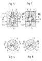
- FIG. 1 shows a swirl nozzle 1 with an inlet channel 2, which forms the inside diameter of a tube, the extension 3 of which protrudes with a length 1 into a cylindrical cavity 4 provided in the swirl nozzle 1. Furthermore, an air injection nozzle 5 merges with the outlet mouth 6 into the cylindrical cavity 4 such that, seen with a view of FIG. 1, the outlet mouth 7 of the inlet channel 2 is lower than the outlet mouth 6 of the air injection nozzle 5. This creates between the cylindrical inner wall 8 of the cavity 4 and the substantially cylindrical outer wall 9 of the tubular extension 3 an annular air duct for the air flow blown through the nozzle 5.
- the air injection nozzle 5 seen with a view of FIG. 1, is arranged on the one hand at an angle such that the axis of symmetry 10 of the injection nozzle 5 has an imaginary plane 11 which intersects the axis of symmetry 10 and, with a view of FIG. 1, perpendicular to the cutting surface and is to the longitudinal axis of this figure, forms an angle ⁇ and on the other hand, as shown in Fig. 2, opens tangentially into the cavity 4.
- the air stream that is blown in creates an air layer that runs around the cylindrical inner wall 8 and shifts in the direction of arrow A.
- the flow direction A creates a negative pressure in the inlet channel 2, according to the jet pump principle, which sucks air through the inlet channel 2 in the direction of the arrow A.
- the tube extension 3 protruding with the length 1 is missing, and the injection nozzles are mounted in such a way that the crank-like rotating yarn core interferes with the structure of the surrounding air layer, since the outlet opening is periodically covered by the rotating yarn crank, since the inflowing air is not forced to form a circumferential layer of air before it catches the yarn core.
- the rotating yarn core is wound by winding fibers which, even after the wrongly twisted yarn core has been untwisted, ensure that the core fibers lying essentially in the axial direction of the yarn are held together in order to thereby produce a usable yarn.
- Such a yarn is, as can be seen from the prior art mentioned, drawn off by a pair of draw-off rollers and fed to a winding device.
- a so-called helix formation in the yarn which continuously decreases towards the pair of draw-off rollers.
- an expanding cone 12 is provided after the cylindrical cavity 4 and has a predetermined length (not shown).
- FIGS. 3 to and 15 show variants of the swirl nozzle according to the invention, which is why the same or essentially the same elements are provided with the same reference numerals or with a decimal place.
- the dimensions of such elements shown can differ from FIG. To FIG.
- FIGS. 3 and 4 show an air nozzle 1 according to FIG. 1, but with an inlet duct 20 which is not essentially as in FIG. 1 a cylindrical, but has a shape at least similar to a Venturi tube.
- the advantage of this "venturi shape” lies in the smaller resistance for the amount of air to be sucked through and also offers the possibility of choosing the narrowest duct cross-section with constant air resistance, in order to create a balloon above the swirl nozzle as required, as seen in FIG. 3 , to prevent. Furthermore, the pipe extension has a mouth edge that is relatively narrow and thus leads to improved airflow and avoids turbulence.
- FIG. 5 shows a further variant in which a narrowing cone 30, viewed in direction A, is connected to the cylindrical cavity 4.1, by means of which the circumferential air layer blown in through the injection nozzle 5 and formed in the cavity 4.1 is narrowed, as a result of which the speed of rotation thereof circulating air layer is increased, with the advantage that the fibers captured by the air layer circulate at a correspondingly higher speed.
- Another advantage of this embodiment is that the narrowing of the air layer means that the fibers sucked in through the inlet channel 2 come into contact with the surrounding air layer more quickly.
- An expanding cone 12.1 is connected to the cone 30 and has the same function as the cone 12 of FIGS. 1 and 3.
- FIG. 7 shows a variant of FIG. 5, in that a constriction 40 is provided instead of the cone 30, which together with the cone 12.1 connected thereto has a shape similar to the Venturi nozzle principle.
- the advantage of the shape should be that of the Venturi nozzle, namely to improve the flow resistance of the air flow in the direction of arrow A and to provide a smoother transition from the narrowing cone 40 to the expanding cone 12.1.
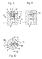
- FIG. 9 shows a further variant of the swirl nozzle of FIG. 1, in that the tubular extension 3 has an annular extension 50 (not shown in section in FIG. 11), which is provided with at least one helical groove 51.
- the annular extension 50 forms a compressed air space 52 with a height B in the cylindrical cavity 4.
- the two, for example, provided grooves 51 connect this compressed air space 52 with the part following the annular extension 50, in direction A. seen, the cylindrical cavity 4th
- the compressed air space 52 can be supplied with compressed air by means of a connecting bore 53.
- this compressed air flows through the helical grooves 51 into the lower part of the cylindrical cavity 4 and forms a circumferential layer of air through the helical shape of the grooves 51, which also moves in the conveying direction A.
- one or a plurality of helical grooves can be provided as required.
- the bore 53 does not necessarily have to open tangentially into the compressed air space 52, as is shown in FIGS. 1 to 8, since the rotation of the air layer is caused by the grooves 51.
- the compressed air space 52 can also be enlarged as desired in order to reduce the air speed therein and to improve the air distribution in the case of a plurality of grooves 51.
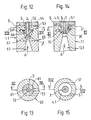
- FIG. 12 shows a variant of the swirl nozzle of FIG. 9, in that a conically shaped, annular extension 60 is provided instead of the cylindrical, annular extension 50.
- one or more helical grooves 61 are also provided, which have the same function as the grooves 51 in FIGS. 9 to 11.
- the extension 60 fits into a narrowing cone 62, which is followed by an expanding cone 63.
- the tube extension 3 is provided, for example, in an end plate 64 which is tightly connected to the nozzle body 65.
- the compressed air space 52 is supplied with compressed air by means of the bore 53, which passes through the helical grooves 61 into the narrowing cone 62 and forms a circumferential air layer therein, the speed of which increases with increasing constriction.
- the widening 60 seen in the direction of conveyance A, can be connected to a narrowing cone 66, the narrowing angle ⁇ of which can be determined empirically. A narrow mouth edge can also be achieved here.
- tubular extension 3 additionally has a conical extension 70 which extends to the narrowest diameter of the cone 30.
- the extension 70 also has a narrow mouth edge. This creates an annular space with a conical cross-section.
- the widening cone 12.1 follows the cone 30
- the ratio length to diameter of the conical extension 70 or. of the cone 30 can be empirically optimized with regard to the desired acceleration of the air flow.
- an air injection nozzle 5.1 opens tangentially into the cylindrical cavity 4.1, the angle ⁇ (see FIG. 1) being essentially 0 degrees (not particularly marked in FIG. 14).
- the compressed air blown in through the air injection nozzle 5.1 is first circulated and secondly accelerated by the narrowing conical ring cross-section 71 in the direction of travel A, so that in the room immediately after the cone 30 or. the cone 70 a umlau air layer is created, which also moves in the conveying direction A.
- FIGS. 16 and 17 show a possible application of the air nozzle shown in FIGS. 1 and 2, it being mentioned that all swirl nozzles shown in FIGS. 1 to 15 could be used in this example.
- FIGS. 16 and 17 corresponds to a modification according to the invention of the false twist nozzle shown in German Design No. 2722319 (St. d. T. mentioned at the beginning).
- the swirl nozzles shown in European patent application No. 0131170 (mentioned at the beginning of St. T.) could also be used.
- 16 shows a hint of an output roller pair 80 of a drafting system (not shown further) and a false twist nozzle body 81.
- the false twist nozzle body 81 viewed in the direction of conveyance A, comprises a feed channel 82, the inlet channel 2 with the tubular extension 3 and the cylindrical cavity 4, the air injection nozzle 5 and an expanding cone 12 connected to the cavity 4.
- the air layer circulating in the cavity 4 sets the yarn core 83 in rotation, as already described in the prior art mentioned, so that a false twist which extends against the pair of output rollers 80 occurs therein.
- the yarn experiences a helix formation and then the swirl of the yarn core 83.
- the yarn is then drawn off by a pair of draw-off rollers (not shown) and fed to a winding device (not shown).
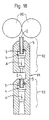
- FIG. 18 shows a further possible application of the swirl nozzles shown with FIGS. 1 to 15.
- the example shows a false twist nozzle modified according to the invention from German laid-open specification DE 3526514 (St. d. T. mentioned at the beginning).
- This example shows a pair of output rollers 90 of a drafting system (not shown) and a false swirl nozzle body 91 with a first swirl nozzle area 92 and a second swirl nozzle area 93.
- the swirl nozzle of the region 93 serves to produce an incorrectly twisted core of yarn which extends in a manner known per se against the pair of output rollers 90, and the swirl nozzle of the region 92 serves in a manner known per se to wind the edge fibers around the incorrectly twisted yarn core.
- the examples shown are not limited to a single injection nozzle 5, but it goes without saying that a plurality of injection nozzles 5 which are uniform or distributed unevenly on the circumference can be used.
Abstract
Description
Die Erfindung betrifft ein Verfahren nach dem Oberbegriff des ersten Verfahrensanspruches und eine Luftdüse nach dem Oberbegriff des Düsenanspruches. Eine solche Düse ist aus der deutschen Auslegeschrift No. 2722319, aus der europäischen Patentanmeldung No. 0131170, sowie aus der deutschen Patentschrift Nr. 3526514 bekannt. Aus diesen Schriften ist ersichtlich, dass solche Düsen als sogenannte Falschdralldüsen in Kombination mit einem Streckwerk verwendet werden, und zwar derart, dass vom Streckwerk ein Faserband angeliefert wird, welches das Faserband in Kernfasern und Randfasern unterteilt. Die Kernfasern werden von der Dralldüse oder im letztgenannten Stand der Technik von der zweiten Dralldüse, in Laufrichtung des Garnes gesehen, zu einem falschgedrehten Garnkern gedreht, welcher sich im wesentlichen vom drallerzeugenden Teil dieser Düse bis hinauf gegen die Ausgangswalzen des Streckwerkes erstreckt. Die Randfasern werden dabei mittels des Lufteinströmkanales oder im letztgenannten Stand der Technik von der ersten Luftdüse, in Laufrichtung des Garnes gesehen, gegen den falschgedrehten Garnkern geführt und um diesen herumgewunden. Diese herumgewundenen Fasern werden als Umwindefasern bezeichnet, welche den nach dem Drallteil der Düse wieder aufgedrehten Garnkern (mit im wesentlichen parallelen Fasern) umwinden und dadurch dem Garn die erforderliche Festigkeit geben.The invention relates to a method according to the preamble of the first method claim and an air nozzle according to the preamble of the nozzle claim. Such a nozzle is from the German design No. 2722319, from European patent application no. 0131170, and also known from German Patent No. 3526514. From these documents it can be seen that such nozzles are used as so-called false twist nozzles in combination with a drafting system, in such a way that the drafting system delivers a sliver that divides the sliver into core fibers and edge fibers. The core fibers are twisted by the twist nozzle or, in the latter prior art, by the second twist nozzle, viewed in the running direction of the yarn, to an incorrectly twisted yarn core, which extends essentially from the twist-generating part of this nozzle up to the exit rollers of the drafting system. The edge fibers are by means of the air inflow channel or in the latter prior art first air nozzle, seen in the direction of the yarn, against the wrongly twisted core and wound around it. These twisted fibers are referred to as wrapping fibers, which wind around the yarn core (with essentially parallel fibers) which has been turned up again after the swirl part of the nozzle and thereby give the yarn the required strength.
Es ist deshalb verständlich, dass das Zuführen der Fasern an den falschgedrehten Garnkern und das darauffolgende Umwinden derart geschieht, dass diese Umwindefasern auch nach dem Zurückdrehen des Garnkernes in die neutrale Lage (in welcher die Fasern im wesentlichen in Längsrichtung im Garn liegen) genügend satt und mit genügender Umschlingung am Garnkern anliegen, damit dem Garn die notwendige Festigkeit erteilt wird.It is therefore understandable that the supply of the fibers to the wrongly twisted yarn core and the subsequent winding takes place in such a way that these wrapping fibers are sufficiently saturated and after the yarn core has been turned back into the neutral position (in which the fibers lie essentially in the longitudinal direction in the yarn) lie on the yarn core with sufficient wrap so that the yarn is given the necessary strength.
Aus dem genannten Stand der Technik ist ersichtlich, dass im drallerzeugenden Teil der Düse Lufteinblasdüsen münden, welche derart gerichtet sind, dass dem vom Streckwerk herkommenden Garnkern eine Drehung erteilt wird, indem dieser Garnkern durch die drehende Luftströmung und der daraus resultierenden Zentrifugalkraft gegen die Innenwand des drallerzeugenden Teiles gebracht wird, so dass am Garnkern ein Kurbeleffekt entsteht, der dem-Garnkern die Falschdrehung erteilt, oder im Falle, dass zwei Dralldüsen in Serie, d.h. in Garnlaufrichtung hintereinander, verwendet werden (siehe DE-PS 3237990), dass die erste Düse die Randfasern an den vorgenannten falschgedrehten Garnkern legt.From the prior art mentioned it can be seen that in the swirl generating part of the nozzle open air injection nozzles, which are directed such that the yarn core coming from the drafting device is given a rotation by this yarn core by the rotating air flow and the resulting centrifugal force against the inner wall of the is brought twist-generating part, so that a crank effect arises on the yarn core, which gives the yarn core the wrong twist, or in the event that two twist nozzles in series, ie one behind the other in the yarn running direction (see DE-PS 3237990) that the first nozzle places the edge fibers on the aforementioned incorrectly rotated yarn core.
In Erkenntnis, dass diese Luftströmung allein zu der vorgenannten Kurbelbildung und damit Drehung des Garn kernes beiträgt, wurde im Laufe der Untersuchungen dieser Luftströmung besondere Aufmerksamkeit gewidmet, um die aus der Luftströmung erforderliche Energie in bezug auf Drehungserteilung und Wirtschaftlichkeit zu optimieren. Dabei soll die Wirtschaftlichkeit einschränkend auf den Vergleich zwischen Energieaufwand und Spinngeschwindigkeit reduziert werden.Recognizing that this air flow alone leads to the aforementioned crank formation and thus twist of the yarn kernes, special attention was paid in the course of the investigations of this air flow in order to optimize the energy required from the air flow in terms of rotation and economy. The economy should be limited to the comparison between energy consumption and spinning speed.
Im weiteren ist es dem sich mit diesen Spinnverfahren befassenden Fachmann bekannt, dass die vorgenannte Luftströmung nicht nur dem Garn eine Drehung, sondern auch einen Vorschub in Garnlaufrichtung erteilen muss, um einen Fadenspannungsanteil im falschgedrehten Garnkern zu erzeugen.Furthermore, it is known to the person skilled in the art dealing with these spinning processes that the aforementioned air flow must not only give the yarn a twist, but also a feed in the yarn running direction in order to generate a yarn tension component in the wrongly twisted yarn core.
Ausserdem ist es aus der europäischen Patentanmeldung No. 0131170 bekannt (gezeigt in den Fig. 4 bis 5a), dass die in den Lufteinströmkanal eingesaugte Luft vor der Drosselstelle abgesaugt wird. Es ist deshalb notwendig, dass die Luftströmung im drallerzeugenden Teil, zusätzlich zu den beiden vorgenannten Merkmalen dieser Strömung, noch eine Saugwirkung erzeugen muss, um genügend Luft aus dem in den Zufuhrkanal fliessenden Luftstrom durch den Einlaufkanal zu saugen, um die am falschgedrehten Garnkern anliegenden Faserenden nicht in die im Einlaufkanal vorgesehene Absaugung abwandern zu lassen.In addition, it is from European patent application No. 0131170 known (shown in FIGS. 4 to 5a) that the air sucked into the air inflow channel is sucked out in front of the throttle point. It is therefore necessary that the air flow in the swirl-generating part, in addition to the two aforementioned features of this flow, must also create a suction effect in order to suck enough air from the air flow flowing into the supply duct through the inlet duct to the fiber ends lying against the wrongly twisted yarn core not to let it migrate into the suction provided in the inlet duct.
Es ist deshalb Aufgabe der Erfindung, die Luftströmung derart zu gestalten, dass sie bezüglich Wirtschaftlichkeit und Drehungserteilung optimal gestaltet ist. Erfindungsgemäss wird diese Aufgabe durch die im Kennzeichen des ersten Verfahrens- und ersten Düsenanspruches aufgeführten Merkmale gelöst.It is therefore an object of the invention to design the air flow in such a way that it is optimally designed with regard to economy and rotation. According to the invention, this object is achieved by the features listed in the characteristics of the first method and first nozzle claim.
Bevorzugte Ausführungsformen sind in den weiteren Ansprüchen definiert.Preferred embodiments are defined in the further claims.
Die Erfindung wird anhand von begleitenden Zeichnungen beispielsweise erläutert.The invention is explained for example with the aid of accompanying drawings.
Es zeigt:
- Fig 1: Eine erfindungsgemässe Dralldüse, halbschematisch und im Schnitt entsprechend den Linien I-I (Fig. 2) dargestellt,
- Fig 2: einen Grundriss von Fig. 1, im Schnitt entsprechend den Linien II-II (Fig. 1) dargestellt,
- die Fig. 3, 5, 7, 9, 12 und 14: je eine Variante der erfindungsgemässen Dralldüse von Fig. 1, je im Schnitt entsprechend den in den Fig. 4, 6, 8, 10, 13 und 15 erwähnten Schnittlinien dargestellt,
- Fig 11: Seitenansicht der Dralldüse von Fig. 9, im Schnitt entsprechend den Schnittlinien XI-XI (Fig. 10) dargestellt,
- Fig 16: Falschdralldüse, unter Verwendung einer erfindungsgemässen Dralldüse, halbschematisch und im Schnitt entsprechend den Linien XVI-XVI (Fig. 17) dargestellt,
- Fig 18: Falschdralldüse mit zwei erfindungsgemässen Dralldüsen, im Längsschnitt dargestellt.
- 1: A swirl nozzle according to the invention, shown semi-schematically and in section along lines II (Fig. 2),
- 2: a floor plan of FIG. 1, shown in section along lines II-II (FIG. 1),
- 3, 5, 7, 9, 12 and 14: each a variant of the swirl nozzle according to the invention from FIG. 1, each shown in section according to the cutting lines mentioned in FIGS. 4, 6, 8, 10, 13 and 15,
- 11: side view of the swirl nozzle of FIG. 9, shown in section along the section lines XI-XI (FIG. 10),
- 16: false twist nozzle, using a swirl nozzle according to the invention, shown semi-schematically and in section along lines XVI-XVI (FIG. 17),
- Fig. 18: False swirl nozzle with two swirl nozzles according to the invention, shown in longitudinal section.
Fig 1 zeigt eine Dralldüse 1 mit einem Einlaufkanal 2, welcher den Innendurchmesser eines Rohres bildet, dessen Fortsatz 3 mit einer Länge 1 in einen in der Dralldüse l vorgesehenen zylindrischen Hohlraum 4 ragt. Im weiteren mundet eine Lufteinblasdüse 5 mit der Austrittsmündung 6 derart in den zylindrischen Hohlraum 4, daß, mit Blick auf Fig. l gesehen, die Austrittsmündung 7 des Einlaufkanales 2 tiefer liegt als die Austrittsmündung 6 der Lufteinblasdüse 5. Dadurch entsteht zwischen der zylindrischen Innenwand 8 des Hohlraumes 4 und der im wesentlichen zylindrischen Außenwand 9 des Rohrfortsatzes 3 eine ringförmige Luftführung für die durch die Düse 5 eingeblasene Luftströmung.1 shows a
Dabei ist die Lufteinblasdüse 5, mit Blick auf Fig. 1 gesehen, einerseits derart schräg angeordnet, daß die Symmetrieachse 10 der Einblasdüse 5 mit einer gedachten Ebene 11, welche die Symmetrieachse 10 schneidet und, mit Blick auf Fig. 1, senkrecht zur Schnittfläche und zur Längsachse dieser Figur steht, einen Winkel α bildet und andererseits, wie in Fig. 2 gezeigt, tangential in den Hohlraum 4 mündet. Durch diese Lage der Einblasduse 5 erzeugt der eingeblasene Luftstrom eine der zylindrischen Innenwand 8 entlang umlaufende und in Pfeilrichtung A sich verschiebende Luftschicht.The
Durch die Strömungsrichtung A entsteht im Einlaufkanal 2, nach dem Strahlpumpenprinzip, ein Unterdruck, welcher Luft durch den Einlaufkanal 2 in Pfeilrichtung A ansaugt.The flow direction A creates a negative pressure in the
Mittels dieser durch den Einlaufkanal 2 eingesaugten Luft werden, wie aus dem erwähnten Stand der Technik bekannt, Fasern durch den Einlaufkanal 2 angesaugt, welche von der umlaufenden Luftschicht erfaßt wer den. Wird die Dralldüse, wie im genannten Stand der Technik erwähnt, als sogenannte Falschdralldüse verwendet, so entsteht im erfassten Garnkern eine Zentrifugalkraft, welche den Garnkern in Form einer Kurbel auslenkt. Ein derart ausgelenkter Garnkern dreht, wie dies am besten aus der Auslegeschrift Nr. 2722319 ersichtlich ist, in der Art einer sich drehenden Kurbel, so dass ein Drall im Garnkern entsteht.By means of this air sucked in through the
Im vorgenannten Stand der Technik fehlt der mit der Länge 1 hineinragende Rohrfortsatz 3, und die Einblasdüsen sind derart gelagert, dass der sich kurbelartig drehende Garnkern störend auf den Aufbau der umlaufenden Luftschicht wirkt, da die Austrittsöffnung periodisch von der umlaufenden Garnkurbel abgedeckt wird, da die einströmende Luft nicht gezwungen wird, eine umlaufende Luftschicht zu bilden, bevor diese den Garnkern erfasst.In the aforementioned prior art, the
Dieser Nachteil wirkt sich darin aus, dass bei gleicher Luftmenge und gleicher Einblasgeschwindigkeit die Drehung im Garnkern kleiner und die Saugwirkung geringer ist als mit der Verwendung des erfindungsgemässen Rohrfortsatzes 3. Da andererseits die Lufteinblasdüse aus praktischen Gründen im wesentlichen zylindrisch hergestellt werden muss, kann im besten Falle die Geschwindigkeit der eingeblasenen Luft der Schallgeschwindigkeit entsprechen.This disadvantage has the effect that, with the same amount of air and the same blowing speed, the twist in the yarn core is smaller and the suction effect is less than with the use of the
Wird nun diese Luftgeschwindigkeit durch Ausführungsarten gemäss des Standes der Technik noch weiter gestört resp. reduziert, so entstehen Verluste in bezug auf den Wirkungsgrad der eingeblasenen Energie.If this air speed is further disturbed by types of execution according to the prior art or. reduced, so there are losses in relation to the efficiency of the injected energy.
Wie aus dem Stand der Technik bekannt ist, wird der sich drehende Garnkern durch Umwindefasern umwunden, welche auch nach dem Entdrallen des falschgedrehten Garnkernes dafür sorgen, dass die im wesentlichen in Achsrichtung des Garnes liegenden Kernfasern zusammengehalten werden, um dadurch ein brauchbares Garn zu erzeugen.As is known from the prior art, the the rotating yarn core is wound by winding fibers which, even after the wrongly twisted yarn core has been untwisted, ensure that the core fibers lying essentially in the axial direction of the yarn are held together in order to thereby produce a usable yarn.
Ein solches Garn wird, wie aus dem genannten Stand der Technik ersichtlich, von einem Abzugswalzenpaar abgezogen und einer Aufwindvorrichtung zugeführt. Durch das Abziehen des Garnes mittels des genannten Abzugswalzenpaares einerseits und durch die vorgenannte Drehung des falschgedrehten Garnes andererseits entsteht im Bereich nach dem zylindrischen Hohlraum 4, d.h. nach dem drallerzeugenden Teil der Dralldüse, eine sogenannte Schraubenlinienbildung im Garn, welche laufend gegen das Abzugswalzenpaar hin abnimmt.Such a yarn is, as can be seen from the prior art mentioned, drawn off by a pair of draw-off rollers and fed to a winding device. By pulling off the yarn by means of said pulling roller pair on the one hand and by the aforementioned rotation of the wrongly twisted yarn on the other hand, in the area after the
Um einer solchen Schraubenlinie, mindestens anfänglich, eine Führung zu geben, ist, in Pfeilrichtung A gesehen, nach dem zylindrischen Hohlraum 4 ein sich erweiternder Konus 12 vorgesehen, welcher eine vorgegebene Länge (nicht gezeigt) aufweist.In order to give guidance to such a helix, at least initially, as seen in the direction of arrow A, an expanding
Mit den folgenden Figuren 3 bis und mit 15 sind Varianten der erfindungsgemässen Dralldüse gezeigt, weshalb gleiche oder im wesentlichen gleiche Elemente mit demselben oder durch eine Dezimalstelle erweiterten Bezugszeichen versehen sind. Dabei können die gezeigten Dimensionen solcher Elemente von Fig. zu Fig. verschieden sein.The following FIGS. 3 to and 15 show variants of the swirl nozzle according to the invention, which is why the same or essentially the same elements are provided with the same reference numerals or with a decimal place. The dimensions of such elements shown can differ from FIG. To FIG.
Im vorgenannten Sinne zeigen die Figuren 3 und 4 eine Luftdüse 1 gemäss Fig. 1, jedoch mit einem Einlaufkanal 20, welcher nicht wie in Fig. 1 im wesentlichen eine zylindrische, sondern eine Form mindestens ähnlich eines Venturi-Rohres aufweist.In the aforementioned sense, FIGS. 3 and 4 show an
Der Vorteil dieser "Venturi-Form" liegt im kleineren Widerstand für den durchzusaugenden Luftanteil und bietet außerdem die Möglichkeit, den engsten Kanalquerschnitt bei gleichbleibendem Luftwiderstand enger zu wahlen, um dadurch je nach Bedarf eine Ballonbildung oberhalb der Dralldüse, mit Blick auf Fig. 3 gesehen, zu verhindern. Weiterhin hat der Rohrfortsatz eine Mundungskante, die relativ eng ist und somit zu einer verbesserten Luftführung führt und Turbulenz vermeidet.The advantage of this "venturi shape" lies in the smaller resistance for the amount of air to be sucked through and also offers the possibility of choosing the narrowest duct cross-section with constant air resistance, in order to create a balloon above the swirl nozzle as required, as seen in FIG. 3 , to prevent. Furthermore, the pipe extension has a mouth edge that is relatively narrow and thus leads to improved airflow and avoids turbulence.
Im weiteren ist mit der Lange 1.1 gezeigt, daß der in den zylindrischen Hohlraum 4 vordringende Rohrfortsatz 3.1 mit einer Länge 1.1 weiter in den Hohlraum hineinragt als mit der Lange 1.Furthermore, it is shown with the length 1.1 that the tube extension 3.1, which projects into the
Die Fig. 5 zeigt eine weitere Variante, indem dem zylindrischen Hohlraum 4.1 ein sich verengender Konus 30, in Richtung A gesehen, angeschlossen ist, mittels welchem die durch die Einblasdüse 5 eingeblasene und im Hohlraum 4.1 gebildete umlaufende Luftschicht verengt wird, wodurch die Drehzahl dieser umlaufenden Luftschicht erhöht wird, mit dem Vorteil, daß auch die von der Luftschicht erfaßten Fasern mit entsprechend höherer Geschwindigkeit umlaufen.FIG. 5 shows a further variant in which a narrowing
Ein weiterer Vorteil dieser Ausführungsform besteht darin, daß durch die Verengung der Luftschicht die durch den Einlaufkanal 2 eingesaugten Fasern rascher in Berührung mit der umlaufenden Luftschicht gelangen.Another advantage of this embodiment is that the narrowing of the air layer means that the fibers sucked in through the
Anschließend an den Konus 30 ist ein erweiternder Konus 12.1 angeschlossen, welcher dieselbe Funktion wie der Konus 12 der Figuren 1 und 3 hat.An expanding cone 12.1 is connected to the
Fig. 7 zeigt eine Variante der Fig. 5, indem anstelle des Konus 30 eine Verengung 40 vorgesehen ist, welche zusammen mit dem daran angeschlossenen Konus 12.1 eine dem Venturi-Düsenprinzip ähnliche Form aufweist.FIG. 7 shows a variant of FIG. 5, in that a
Der Vorteil der Form soll derjenige der Venturi-Düse sein, nämlich den Durchlaufwiderstand der Luftströmung in der Pfeilrichtung A zu verbessern und einen sanfteren Übergang vom verengenden Konus 40 zum erweiternden Konus 12.1 vorzusehen.The advantage of the shape should be that of the Venturi nozzle, namely to improve the flow resistance of the air flow in the direction of arrow A and to provide a smoother transition from the narrowing
Die Fig. 9 zeigt eine weitere Variante der Dralldüse von Fig. 1, indem der Rohrfortsatz 3 eine ringförmige Erweiterung 50 (in Fig. 11 nicht geschnitten gezeigt) aufweist, welche mit mindestens einer schraubenförmigen Nute 51 versehen ist.FIG. 9 shows a further variant of the swirl nozzle of FIG. 1, in that the
Die ringförmige Erweiterung 50 bildet im zylindrischen Hohlraum 4 einen Druckluftraum 52 mit einer Höhe B. Die zwei, beispielsweise, vorgesehenen Nuten 51 (in Fig. 11 nur eine sichtbar) verbinden diesen Druckluftraum 52 mit dem der ringförmigen Erweiterung 50 nachfolgenden Teil, in Richtung A gesehen, des zylindrischen Hohlraumes 4.The
Mittels einer Verbindungsbohrung 53 kann der Druckluftraum 52 mit Druckluft beschickt werden.The
Diese Druckluft strömt im Betrieb durch die schraubenförmigen Nuten 51 in den genannten unteren Teil des zylindrischen Hohlraumes 4 und bildet durch die Schraubenform der Nuten 51 in diesem Raum eine umlaufende Luftschicht, welche sich zusätzlich noch in Förderrichtung A bewegt.During operation, this compressed air flows through the
Es versteht sich, dass je nach Bedarf eine oder eine Mehrzahl schraubenförmiger Nuten vorgesehen werden kann.It goes without saying that one or a plurality of helical grooves can be provided as required.
Im weiteren ist darauf hinzuweisen, dass die Bohrung 53 nicht notwendigerweise tangential in den Druckluftraum 52 münden muss, wie dies mit den Figuren 1 bis 8 gezeigt ist, da das Drehen der Luftschicht durch die Nuten 51 verursacht wird.It should also be pointed out that the
Ebenfalls kann der Druckluftraum 52 beliebig vergrössert werden, um darin die Luftgeschwindigkeit zu verkleinern und die Luftverteilung bei mehreren Nuten 51 zu verbessern.The
Die Fig. 12 zeigt eine Variante der Dralldüse von Fig. 9, indem anstelle der zylindrisch gestalteten, ringförmigen Erweiterung 50 eine konisch gestaltete, ringförmige Erweiterung 60 vorgesehen ist.FIG. 12 shows a variant of the swirl nozzle of FIG. 9, in that a conically shaped, annular extension 60 is provided instead of the cylindrical,
In dieser Erweiterung 60 sind ebenfalls eine oder mehrere schraubenförmige Nuten 61 vorgesehen, welche die selbe Funktion haben wie die Nuten 51 in den Fig. 9 bis 11.In this extension 60, one or more
Die Erweiterung 60 fügt sich in einen sich verengenden Konus 62 ein, welchem ein sich erweiternder Konus 63 anschliesst.The extension 60 fits into a narrowing
Aus rein herstellungstechnischen Gründen ist der Rohrfortsatz 3 beispielsweise in einer Abschlussplatte 64 vorgesehen, welche dicht mit dem Düsenkörper 65 verbunden ist.For purely technical reasons, the
im Betrieb wird der Druckluftraum 52 mittels der Bohrung 53 mit Druckluft beschickt, welche durch die schraubenförmigen Nuten 61 in den sich verengenden Konus 62 tritt und darin eine umlaufende Luftschicht bildet, deren Drehzahl mit zunehmender Verengung zunimmt. Zur Verbesserung der Luftfuhrung kann der Erweiterung 60, in Förderrichtung A gesehen, ein sich verengender Konus 66 angeschlossen werden, dessen Verengungswinkel α empirisch ermittelt werden kann. Auch hier kann eine enge Mündungskante erzielt werden.in operation, the
Die Fig. 14 und 15 zeigen eine Variante der Dralldüse der Fig. 5 und 6, indem der Rohrfortsatz 3 zusätzlich eine konische Verlängerung 70 aufweist, welche sich bis zum engsten Durchmesser des Konus 30 erstreckt. Die Verlängerung 70 weist auch eine enge Mündungskante auf. Dadurch entsteht ein ringförmiger Raum von konischem Querschnitt. Anschließend an den Konus 30 folgt der erweiternde Konus 12.114 and 15 show a variant of the swirl nozzle of FIGS. 5 and 6, in that the
Das Verhältnis Länge zu Durchmesser der konischen Verlangerung 70 resp. des Konus 30 kann bezüglich gewünschter Beschleunigung der Luftströmung empirisch optimiert werden.The ratio length to diameter of the
Oberhalb des Konus 30, mit Blickrichtung auf Fig. 14 gesehen, mündet eine Lufteinblasdüse 5.1 tangential in den zylindrischen Hohlraum 4.1 ein, wobei der Winkel α siehe Fig. 1) im wesentlichen 0 Grad ist (in Fig. 14 nicht besonders gekennzeichnet).Above the
Durch diese Anordnung der beiden koaxialen Konen wird die durch die Lufteinblasdüse 5.1 eingeblasene Druckluft erstens in Umlauf versetzt und zweitens durch den verengenden konischen Ringquerschnitt 71 in Forderrichtung A beschleunigt, so daß im Raum unmittelbar nach dem Konus 30 resp. dem Konus 70 eine umlau fende Luftschicht entsteht, welche sich ebenfalls in Förderrichtung A bewegt.With this arrangement of the two coaxial cones, the compressed air blown in through the air injection nozzle 5.1 is first circulated and secondly accelerated by the narrowing
Die Fig. 16 und 17 zeigen eine Verwendungsmöglichkeit der mit den Fig. 1 und 2 gezeigten Luftdüse, wobei erwähnt sei, dass sämtliche in den Figuren 1 bis 15 gezeigten Dralldüsen in diesem Beispiel verwendet werden könnten.16 and 17 show a possible application of the air nozzle shown in FIGS. 1 and 2, it being mentioned that all swirl nozzles shown in FIGS. 1 to 15 could be used in this example.
Das mit den Fig. 16 und 17 gezeigte Beispiel entspricht einer erfindungsgemässen Modifikation der in der deutschen Auslegeschrift Nr. 2722319 (eingangs erwähnter St. d. T.) gezeigten Falschdralldüse. Anstelle dieser Düse könnten ebenfalls die in der europäischen Patentanmeldung Nr. 0131170 (eingangs erwähnter St. d. T.) gezeigten Dralldüsen verwendet werden.The example shown with FIGS. 16 and 17 corresponds to a modification according to the invention of the false twist nozzle shown in German Design No. 2722319 (St. d. T. mentioned at the beginning). Instead of this nozzle, the swirl nozzles shown in European patent application No. 0131170 (mentioned at the beginning of St. T.) could also be used.
Dabei zeigt die Fig. 16 andeutungsweise ein Ausgangswalzenpaar 80 eines nicht weiter gezeigten Streckwerkes sowie einen Falschdralldüsenkörper 81.16 shows a hint of an
Der Falschdralldüsenkörper 81 umfasst in Förderrichtung A gesehen einen Zufuhrkanal 82, den Einlaufkanal 2 mit dem Rohrfortsatz 3 und dem zylindrischen Hohlraum 4, die Lufteinblasdüse 5 sowie einen an den Hohlraum 4 angeschlossenen erweiternden Konus 12.The false
Die im Hohlraum 4 umlaufende Luftschicht versetzt den Garnkern 83, wie bereits im erwähnten Stand der Technik beschrieben, in Rotation, so dass darin eine sich gegen das Ausgangswalzenpaar 80 erstreckende Falschdrehung entsteht.The air layer circulating in the
Im erweiternden Konus 12 erfährt das Garn eine Schraubenlinienbildung und anschliessend die Entdrallung des Garnkernes 83. Das Garn wird anschliessend von einem Abzugswalzenpaar (nicht gezeigt) abgezogen und einer Aufwindvorrichtung (nicht gezeigt) zugeführt.In the widening
Die Fig. 18 zeigt eine weitere Anwendungsmöglichkeit der mit den Fig. 1 bis 15 gezeigten Dralldüsen. Das Beispiel zeigt eine erfindungsgemäss modifizierte Falschdralldüse aus der deutschen Offenlegungsschrift DE 3526514 (eingangs erwähnter St. d. T.). Dieses Beispiel zeigt ein Ausgangswalzenpaar 90 eines weiter nicht gezeigten Streckwerkes sowie einen Falschdralldüsenkörper 91 mit einem ersten Dralldüsenbereich 92 und einem zweiten Dralldüsenbereich 93.FIG. 18 shows a further possible application of the swirl nozzles shown with FIGS. 1 to 15. The example shows a false twist nozzle modified according to the invention from German laid-open specification DE 3526514 (St. d. T. mentioned at the beginning). This example shows a pair of
Die Dralldüse des Bereiches 93 dient zur Erzeugung eines falschgedrehten Garnkernes, welcher sich in an sich bekannter Weise gegen das Ausgangswalzenpaar 90 erstreckt, und die Dralldüse des Bereiches 92 dient in an sich bekannter Weise, um die Randfasern um den falschgedrehten Garnkern herumzuwinden.The swirl nozzle of the
Es sei auch im Zusammenhang mit diesem Beispiel erwähnt, dass, wenn auch die Luftdüse der Fig. 1 und 2 bspw. in dieser Variante Verwendung finden, sämtliche weiteren Varianten, sei es im ersten oder zweiten Düsenbereich, verwendet werden können.It should also be mentioned in connection with this example that, even if the air nozzle of FIGS. 1 and 2 are used in this variant, for example, all further variants, be it in the first or second nozzle region, can be used.
Die weiteren Details dieser Variante seien der Einfachheit halber nicht weiter erwähnt, sondern es sei auf den erwähnten Stand der Technik verwiesen.For the sake of simplicity, the further details of this variant should not be mentioned further, but reference should be made to the prior art mentioned.
Letztlich sei erwähnt, dass innerhalb der mit den Fig. 1 bis 15 gezeigten Varianten Variationen untereinander gewählt werden können, bspw., dass der Einlaufkanal 20 auch in den übrigen Beispielen verwendet werden kann, oder dass die mit der Fig. 7 gezeigte Venturi-Form auch mit den mit den Fig. 12 und 14 gezeigten Varianten kombiniert werden kann.Finally, it should be mentioned that within the variants shown in FIGS. 1 to 15, variations among one another can be selected, for example that the
Ebenso sind die gezeigten Beispiele nicht auf eine einzige Einblasdüse 5 eingeschränkt, sondern es versteht sich, dass eine Mehrzahl von gleichmässigen oder am Umfang ungleichmässig verteilten Einblasdüsen 5 Verwendung finden kann.Likewise, the examples shown are not limited to a
Claims (19)
dadurch gekennzeichnet,
daß diese Luftschicht gebildet wird, bevor diese die Fasern erfaßt.1. Method for generating a circumferential air layer in a swirl-generating part of an air nozzle, by means of which fibers are brought into a rotational movement,
characterized,
that this air layer is formed before it catches the fibers.
dadurch gekennzeichnet,
daß die Fasern ein Garn bilden, das vorzugsweise in Drehung versetzt wird.2. The method according to claim 1,
characterized,
that the fibers form a yarn that is preferably rotated.
dadurch gekennzeichnet,
daß die Fasern einen Garnkern eines sogenannten Falschdrallgarnes bilden.3. The method according to claim 1,
characterized,
that the fibers form a yarn core of a so-called false twist yarn.
dadurch gekennzeichnet,
daß die Fasern die Umwindefasern eines falschgedrehten Garnkernes eines sogenannten Falschdrallgarnes sind.4. The method according to claim 1,
characterized,
that the fibers are the wrapping fibers of a wrongly twisted core of a so-called false twist yarn.
dadurch gekennzeichnet,
daß die Luftschicht den Fasern nebst der Drehungserteilungs-Komponente auch eine Komponente in Förderrichtung vermittelt, die vorzugsweise in Garnlaufrichtung verläuft.5. The method according to claim 1,
characterized,
that the air layer conveys to the fibers, in addition to the twist-imparting component, a component in the conveying direction, which preferably runs in the yarn running direction.
dadurch gekennzeichnet,
daß die Luftschicht durch Leitelemente gelenkt wird, und daß die Luftschicht vorzugsweise für das Ansau gen einer Transportluft, nach dem Prinzip der Strahlpumpe, verwendet wird, mittels welcher die Fasern in den drallerzeugenden Teil transportiert werden, so daß sie von der Luftschicht erfaßt werden können.6. The method according to claim 1,
characterized,
that the air layer is directed by guide elements, and that the air layer is preferably for suction gene transport air, is used on the principle of the jet pump, by means of which the fibers are transported into the swirl generating part so that they can be detected by the air layer.
dadurch gekennzeichnet,
daß im drallerzeugenden Teil eine Luftführung derart vorgesehen ist, daß sich der Luftstrom zu einer umlaufenden Luftschicht ausbildet, bevor diese die eingesaugten Fasern erfaßt.7. swirl nozzle with a central inlet channel, an adjoining swirl-generating part of round cross-section, and with at least one air blowing means provided in this part for blowing in an air stream to form a circumferential air layer in this part and for sucking fibers into this part,
characterized,
that an air duct is provided in the swirl-generating part in such a way that the air flow forms into a circumferential air layer before it detects the sucked-in fibers.
dadurch gekennzeichnet,
daß das Lufteinblasmittel mindestens eine Lufteinblasdüse ist, welche tangential in den drallerzeugenden Teil mündet und daß die Luftführung ein derart in den genannten Teil hineinragendes Rohr ist, daß die Luftströmung eine Führung zwischen der Innenwand des genannten Teiles und der Außenwand erfährt, wobei das Rohr vorzugsweise mindestens soweit in den Eingangsbereich ragt, daß das Rohr, in Richtung eines Längsschnittes des Rohres gesehen, die Mündung der Lufteinblasdüse abdeckt.8. swirl nozzle according to claim 7,
characterized,
that the air injection means is at least one air injection nozzle which opens tangentially into the swirl-generating part and that the air duct is such a pipe protruding into said part that the air flow is guided between the inner wall of said part and the outer wall, the pipe preferably at least extends so far into the entrance area that the tube, seen in the direction of a longitudinal section of the tube, covers the mouth of the air injection nozzle.
dadurch gekennzeichnet,
daß die Außenwand des Rohres und die Innenwand des drallerzeugenden Teiles zylindrisch sind.9. swirl nozzle according to claim 8,
characterized,
that the outer wall of the tube and the inner wall of the swirl-generating part are cylindrical.
dadurch gekennzeichnet,
daß die Lufteinblasdüse derart vorgesehen ist, daß die eingeblasene Luftströmung im wesentlichen an der Innenwand des Eingangsbereiches entlangströmt und daß der Abstand zwischen der Innenwand des Eingangsbereiches und der Außenwand des Rohres derart gewählt wird, daß die Luftströmung in Umfangsrichtung gesehen nach dem Einströmen in den Eingangsbereich mindestens keine Erweiterung erfährt.10. swirl nozzle according to claim 9,
characterized,
that the air injection nozzle is provided in such a way that the blown-in air flow essentially flows along the inner wall of the input area and that the distance between the inner wall of the input area and the outer wall of the tube is selected such that the air flow is seen in the circumferential direction at least after flowing into the input area undergoes no expansion.
dadurch gekennzeichnet,
daß der drallerzeugende Teil nach der zylindrischen Innenwand eine konische Erweiterung aufweist.11. swirl nozzle according to claim 9,
characterized,
that the swirl generating part has a conical widening after the cylindrical inner wall.
dadurch gekennzeichnet,
daß der drallerzeugende Teil nach der zylindrischen Innenwand eine Verengung aufweist, wobei vorzugsweise eine Erweiterung sich an die Verengung anschließt und die Verengung insbesondere einen Konus mit geradliniger Mantellinie aufweist, wobei die Verengung und Erweiterung vorteilhafterweise mindestens ähnlich dem Venturi-Rohr-Prinzip ausgebildet sein können.12. swirl nozzle according to claim 9,
characterized,
that the swirl-generating part has a constriction after the cylindrical inner wall, an expansion preferably adjoining the constriction and the constriction in particular having a cone with a rectilinear surface line, the constriction and expansion advantageously being able to be designed at least similar to the venturi tube principle.
dadurch gekennzeichnet,
daß der Einlaufkanal im wesentlichen zylindrisch ist oder im wesentlichen die Form eines VenturiRohres aufweist.13. swirl nozzle according to claim 7,
characterized,
that the inlet channel is essentially cylindrical or has the shape of a Venturi tube.
dadurch gekennzeichnet,
daß der drallerzeugende Teil eine zylindrische Innenwand umfaßt, daß das Lufteinblasmittel ein in diese Innenwand ragender und von der Innenwand geführter zylindrischer Ringkörper ist, dessen Innenwand eine Fortsetzung des Einlaufkanales ist und daß der Ringkorper als genannte Luftführung mindestens eine schraubenförmige Rille umfaßt, durch welche der genannte Luftstrom in den drallerzeugenden Teil eingeblasen wird.14. swirl nozzle according to claim 7,
characterized,
that the swirl generating part comprises a cylindrical inner wall, that the air injection means a in this inner wall projecting and guided by the inner wall is a cylindrical ring body, the inner wall of which is a continuation of the inlet channel and that the ring body, as said air duct, comprises at least one helical groove through which said air flow is blown into the swirl-generating part.
dadurch gekennzeichnet,
daß der drallerzeugende Teil eine konische Innenwand umfaßt, daß das Lufteinblasmittel ein an dieser Innenwand anliegender konischer Ringkörper ist, dessen Innenwand eine Fortsetzung des Einlaufkanales ist und daß der Ringkörper als genannte Luftführung mindestens eine schraubenformige Rille umfaßt, durch welche der genannte Luftstrom in den drallerzeugenden Teil geblasen wird.15. swirl nozzle according to claim 7,
characterized,
that the swirl-generating part comprises a conical inner wall, that the air blowing means is a conical ring body lying against this inner wall, the inner wall of which is a continuation of the inlet channel, and that the ring body, as the air duct, comprises at least one helical groove through which the air flow into the swirl-generating part is blown.
dadurch gekennzeichnet,
daß oberhalb des Ringkörpers, mit Blickrichtung auf die Figuren gesehen, ein Luftraum vorgesehen ist, in welchem zur Erzeugung des genannten Luftstromes ein Überdruck erzeugt wird.16. swirl nozzle according to claim 14 and 15,
characterized,
that above the ring body, as viewed in the direction of the figures, an air space is provided in which an overpressure is generated to generate the air flow mentioned.
dadurch gekennzeichnet,
daß der konischen Innenwand ein diffusorförmiger Kanal angeschlossen ist.17. swirl nozzle according to claim 15,
characterized,
that a diffuser-shaped channel is connected to the conical inner wall.
dadurch gekennzeichnet,
daß der drallerzeugende Teil einen ringförmigen, den Einlaufkanal umringenden Hohlraum in Form eines Trichters umfaßt, dessen ringförmige Auslaufmundung im wesentlichen auf gleicher Höhe liegt, in Blick richtung auf die Figur gesehen, wie die Auslaufmundung des Einlaufkanales, sowie, daß anschließend an die Auslaufmündung des Trichters ein diffusorförmiger Kanal angeschlossen ist.18. swirl nozzle according to claim 7,
characterized,
that the swirl-generating part comprises an annular cavity surrounding the inlet channel in the form of a funnel, the annular outlet mouth of which is essentially at the same height Direction seen on the figure, as the outlet mouth of the inlet channel, and that a diffuser-shaped channel is then connected to the outlet mouth of the funnel.
Applications Claiming Priority (2)
| Application Number | Priority Date | Filing Date | Title |
|---|---|---|---|
| CH4950/87 | 1987-12-18 | ||
| CH495087 | 1987-12-18 |
Publications (1)
| Publication Number | Publication Date |
|---|---|
| EP0321885A1 true EP0321885A1 (en) | 1989-06-28 |
Family
ID=4285351
Family Applications (1)
| Application Number | Title | Priority Date | Filing Date |
|---|---|---|---|
| EP88121141A Withdrawn EP0321885A1 (en) | 1987-12-18 | 1988-12-16 | Pneumatic nozzle for false twisting |
Country Status (3)
| Country | Link |
|---|---|
| US (1) | US4934133A (en) |
| EP (1) | EP0321885A1 (en) |
| JP (1) | JPH01162829A (en) |
Cited By (9)
| Publication number | Priority date | Publication date | Assignee | Title |
|---|---|---|---|---|
| EP0415295A1 (en) * | 1989-09-01 | 1991-03-06 | Maschinenfabrik Rieter Ag | Method of false twist spinning and device for carrying out the method |
| EP0418693A1 (en) * | 1989-09-21 | 1991-03-27 | Maschinenfabrik Rieter Ag | Nozzle of an air jet spinning machine |
| EP0418694A1 (en) * | 1989-09-22 | 1991-03-27 | Maschinenfabrik Rieter Ag | Airjet spinning machine with an injection nozzle and a twisting nozzle |
| EP0489686A1 (en) * | 1990-12-06 | 1992-06-10 | Maschinenfabrik Rieter Ag | Nozzle for producing a swirl in an air jet spinning machine |
| US5237810A (en) * | 1989-09-01 | 1993-08-24 | Maschinenfabrik Rieter Ag | Method and apparatus for false twist spinning |
| WO1994003662A1 (en) * | 1992-07-31 | 1994-02-17 | Maschinenfabrik Rieter Ag | Device for spinning a sliver |
| EP0854214A2 (en) * | 1997-01-16 | 1998-07-22 | Murata Kikai Kabushiki Kaisha | Spinning Apparatus |
| CN101798717A (en) * | 2010-01-07 | 2010-08-11 | 杭州益邦氨纶有限公司 | Device for checking spandex false twister |
| CH712489A1 (en) * | 2016-05-26 | 2017-11-30 | Rieter Ag Maschf | Garnbildungselement for a roving and equipped therewith roving. |
Families Citing this family (5)
| Publication number | Priority date | Publication date | Assignee | Title |
|---|---|---|---|---|
| US5775079A (en) * | 1997-04-21 | 1998-07-07 | American Linc Corporation | Apparatus for imparting virtual twist to strand material and method of imparting same |
| GB9814476D0 (en) * | 1998-07-04 | 1998-09-02 | Fibreguide Ltd | Yarn treatment jet |
| AU2790600A (en) * | 1999-03-03 | 2000-09-21 | Heberlein Fibertechnology, Inc. | Method and device for processing filament yarn, and use of said device |
| EP1608804B1 (en) * | 2003-03-28 | 2010-08-25 | Oerlikon Heberlein Temco Wattwil AG | Texturing nozzle and method for texturing a filament yarn |
| EP1621649B1 (en) * | 2004-07-28 | 2008-09-10 | FARE' S.p.A. | Apparatus and method for treating synthetic yarns |
Citations (3)
| Publication number | Priority date | Publication date | Assignee | Title |
|---|---|---|---|---|
| US3490219A (en) * | 1966-12-29 | 1970-01-20 | Mitsubishi Rayon Co | Super high speed spinning method and apparatus for manufacturing jet bundle yarn |
| GB2174723A (en) * | 1985-05-07 | 1986-11-12 | Npk Textilno Mash | Air vortex nozzle for spinning yarn from staple fibres |
| WO1987003310A1 (en) * | 1985-11-21 | 1987-06-04 | Schubert & Salzer Maschinenfabrik Aktiengesellscha | Process and device for rethreading a spinning device provided with a pneumatic twisting element |
Family Cites Families (13)
| Publication number | Priority date | Publication date | Assignee | Title |
|---|---|---|---|---|
| US3425359A (en) * | 1966-09-20 | 1969-02-04 | Japan National Railway | Apparatus for handling track installations |
| DE2722319B2 (en) * | 1977-01-10 | 1981-01-15 | Toyo Boseki K.K., Osaka (Japan) | Device for pneumatic false twist spinning |
| JPS5837259B2 (en) * | 1977-08-02 | 1983-08-15 | 株式会社東芝 | Manufacturing method of glass fiber for optical communication |
| JPS5625524A (en) * | 1979-08-07 | 1981-03-11 | Nissho Kosan Kk | Hinge structure of lid |
| US4242859A (en) * | 1980-01-21 | 1981-01-06 | Lawrence M. Keeler | Thread spinning apparatus |
| US4457130A (en) * | 1981-10-13 | 1984-07-03 | Murata Kikai Kabushiki Kaisha | Air spinning nozzle unit |
| US4437302A (en) * | 1982-01-20 | 1984-03-20 | Kabushiki Kaisha Toyoda Jidoshokki Seisakusho | False twisting air nozzle |
| IN161355B (en) * | 1983-07-01 | 1987-11-14 | Rieter Ag Maschf | |
| DE3402460A1 (en) * | 1984-01-25 | 1985-08-01 | W. Schlafhorst & Co, 4050 Mönchengladbach | SWIRLERS |
| US4569193A (en) * | 1984-06-04 | 1986-02-11 | Kabushiki Kaisha Toyoda Jidoshokki Seisakusho | Apparatus for producing a fasciated yarn |
| JPS6134234A (en) * | 1984-07-26 | 1986-02-18 | Murata Mach Ltd | Apparatus for open end spinning |
| JPS6288768A (en) * | 1985-10-11 | 1987-04-23 | Hitachi Ltd | Tape feed control method and its device |
| EP0317652B1 (en) * | 1987-11-23 | 1992-01-22 | Toray Industries, Inc. | Suction device for yarnthreading |
-
1988
- 1988-11-25 JP JP63296420A patent/JPH01162829A/en active Pending
- 1988-12-15 US US07/288,415 patent/US4934133A/en not_active Expired - Fee Related
- 1988-12-16 EP EP88121141A patent/EP0321885A1/en not_active Withdrawn
Patent Citations (3)
| Publication number | Priority date | Publication date | Assignee | Title |
|---|---|---|---|---|
| US3490219A (en) * | 1966-12-29 | 1970-01-20 | Mitsubishi Rayon Co | Super high speed spinning method and apparatus for manufacturing jet bundle yarn |
| GB2174723A (en) * | 1985-05-07 | 1986-11-12 | Npk Textilno Mash | Air vortex nozzle for spinning yarn from staple fibres |
| WO1987003310A1 (en) * | 1985-11-21 | 1987-06-04 | Schubert & Salzer Maschinenfabrik Aktiengesellscha | Process and device for rethreading a spinning device provided with a pneumatic twisting element |
Cited By (13)
| Publication number | Priority date | Publication date | Assignee | Title |
|---|---|---|---|---|
| US5237810A (en) * | 1989-09-01 | 1993-08-24 | Maschinenfabrik Rieter Ag | Method and apparatus for false twist spinning |
| EP0415295A1 (en) * | 1989-09-01 | 1991-03-06 | Maschinenfabrik Rieter Ag | Method of false twist spinning and device for carrying out the method |
| EP0418693A1 (en) * | 1989-09-21 | 1991-03-27 | Maschinenfabrik Rieter Ag | Nozzle of an air jet spinning machine |
| EP0418694A1 (en) * | 1989-09-22 | 1991-03-27 | Maschinenfabrik Rieter Ag | Airjet spinning machine with an injection nozzle and a twisting nozzle |
| CH682566A5 (en) * | 1990-12-06 | 1993-10-15 | Rieter Ag Maschf | Nozzle for swirl generation in a jet spinning machine. |
| US5230210A (en) * | 1990-12-06 | 1993-07-27 | Maschinenfabrick Rieter Ag | Nozzle for generating a twist in a jet spinning machine |
| EP0489686A1 (en) * | 1990-12-06 | 1992-06-10 | Maschinenfabrik Rieter Ag | Nozzle for producing a swirl in an air jet spinning machine |
| WO1994003662A1 (en) * | 1992-07-31 | 1994-02-17 | Maschinenfabrik Rieter Ag | Device for spinning a sliver |
| EP0854214A2 (en) * | 1997-01-16 | 1998-07-22 | Murata Kikai Kabushiki Kaisha | Spinning Apparatus |
| EP0854214A3 (en) * | 1997-01-16 | 1999-06-09 | Murata Kikai Kabushiki Kaisha | Spinning Apparatus |
| CN101798717A (en) * | 2010-01-07 | 2010-08-11 | 杭州益邦氨纶有限公司 | Device for checking spandex false twister |
| CH712489A1 (en) * | 2016-05-26 | 2017-11-30 | Rieter Ag Maschf | Garnbildungselement for a roving and equipped therewith roving. |
| US10900144B2 (en) | 2016-05-26 | 2021-01-26 | Maschinenfabrik Rieter Ag | Roving-forming element for a roving machine as well as a roving machine equipped therewith |
Also Published As
| Publication number | Publication date |
|---|---|
| US4934133A (en) | 1990-06-19 |
| JPH01162829A (en) | 1989-06-27 |
Similar Documents
| Publication | Publication Date | Title |
|---|---|---|
| DE2660983C2 (en) | Process for pneumatic twist spinning | |
| EP1223236B1 (en) | Device for making a core yarn | |
| EP0321885A1 (en) | Pneumatic nozzle for false twisting | |
| DE3722771C1 (en) | Device for bringing together a textile nonwoven fabric into a sliver | |
| EP1332248A2 (en) | Spinning device | |
| CH692744A5 (en) | Fadenabzugdüse. | |
| DE3207136A1 (en) | METHOD AND DEVICE FOR PRODUCING A THREAD | |
| DE3639031C2 (en) | ||
| CH679491A5 (en) | ||
| EP0121602A1 (en) | False-twister | |
| EP0305971B1 (en) | Method and device for false-twist spinning | |
| EP0175862B1 (en) | Method and device for the production of yarn | |
| EP1217110A2 (en) | Spinning device | |
| EP0712947B1 (en) | Open-end spinning device | |
| AT501520B1 (en) | GARNABZUGSEINICHTUNG FOR OPENING SPINNING DEVICES | |
| EP1415027B1 (en) | Device for producing a spun yarn | |
| DE3346045A1 (en) | METHOD FOR SPINNING YARN FROM STACKED FIBERS IN AN AIR BURN AND DEVICE FOR CARRYING OUT THIS METHOD | |
| EP3144419B1 (en) | Channel plate adapter and open ended spinning machine with a channel plate adapter | |
| EP0205840B1 (en) | Method and apparatus for open-end friction spinning | |
| CH659666A5 (en) | DEVICE FOR PRODUCING BUNCH YARN. | |
| EP1587974B1 (en) | Method for producing a spun thread | |
| EP0222101A1 (en) | Method for piecing a yarn in a friction-spinning device | |
| CH676725A5 (en) | ||
| EP0363649B1 (en) | Friction-spinning apparatus | |
| EP0017935A1 (en) | Process for manufacturing yarn from bulk fibres and apparatus for carrying out this process |
Legal Events
| Date | Code | Title | Description |
|---|---|---|---|
| PUAI | Public reference made under article 153(3) epc to a published international application that has entered the european phase |
Free format text: ORIGINAL CODE: 0009012 |
|
| AK | Designated contracting states |
Kind code of ref document: A1 Designated state(s): AT CH DE ES FR GB IT LI |
|
| 17P | Request for examination filed |
Effective date: 19890817 |
|
| 17Q | First examination report despatched |
Effective date: 19910129 |
|
| STAA | Information on the status of an ep patent application or granted ep patent |
Free format text: STATUS: THE APPLICATION IS DEEMED TO BE WITHDRAWN |
|
| 18D | Application deemed to be withdrawn |
Effective date: 19941201 |