EP1331734A2 - Verfahren zur Koeffizientenadaption bei einem digitalen Filter nach dem Equation-Error-Prinzip - Google Patents
Verfahren zur Koeffizientenadaption bei einem digitalen Filter nach dem Equation-Error-Prinzip Download PDFInfo
- Publication number
- EP1331734A2 EP1331734A2 EP03001775A EP03001775A EP1331734A2 EP 1331734 A2 EP1331734 A2 EP 1331734A2 EP 03001775 A EP03001775 A EP 03001775A EP 03001775 A EP03001775 A EP 03001775A EP 1331734 A2 EP1331734 A2 EP 1331734A2
- Authority
- EP
- European Patent Office
- Prior art keywords
- equation
- error
- coefficients
- filter
- matrix
- Prior art date
- Legal status (The legal status is an assumption and is not a legal conclusion. Google has not performed a legal analysis and makes no representation as to the accuracy of the status listed.)
- Withdrawn
Links
Images

Classifications
-
- H—ELECTRICITY
- H03—ELECTRONIC CIRCUITRY
- H03H—IMPEDANCE NETWORKS, e.g. RESONANT CIRCUITS; RESONATORS
- H03H21/00—Adaptive networks
- H03H21/0012—Digital adaptive filters
- H03H21/0043—Adaptive algorithms
Definitions
- the invention relates to a method for coefficient adaptation in a digital filter the equation error principle.
- Digital signal processing deals, among other things, with the so-called optimal filter problem.
- This consists in adapting the output sequence of a linear time-invariant filter y (n) ("estimation sequence"), which belongs to an input sequence x (n), by adapting the filter parameters as well as possible to a reference sequence d (n) ("desired sequence") (Fig.1).
- a reference sequence d (n) (“desired sequence") (Fig.1).
- filters of type “FIR (Finite Impulse Response)" of length P are used, the coefficients of which are adapted, hence the output sequence y (n) only as a linear combination of the terms of the input sequence x (n), according to equation G.1 . educated.
- the coefficient set of an FIR filter is usually only gradually determined using the so-called Least Mean Squares (LMS) algorithm.
- LMS Least Mean Squares
- the elements of the optimal coefficient vector h opt (n) can be determined for the values visible in this current section. If the window continues to move from the reference point n to n + 1- in order to determine h opt (n + 1) - the entire calculation would have to be performed again, although only the values x (n + K) and d (n + K) are added and x (n-P + 1) and d (n) are eliminated. A recursive determination of h opt (n + 1) from h opt (n) therefore appears to be desirable and is possible by means of the algorithm described in DE197 02 321 because of the small amount of data changing during the transition from n to n + 1.
- the invention is based on the object of a method for very well approximated determination the coefficient set of an IIR filter with the system function (G.2) with the shortest possible Specify learning time.
- the optimal filter problem is described in more detail below with reference to FIG. It is based on predefined data sequences, not on random processes.
- the data sequences x (0), x (1) .. x (N s - 1) and d (0), d (1) .. d (N s - 1) are given; if a causal FIR filter of length P is used, y (n) according to G.1 is obtained for the sequence determined on the basis of x (n) and d (n) as an estimate of d (n).
- the goal is to find the "best unit impulse response vector" h opt (n).
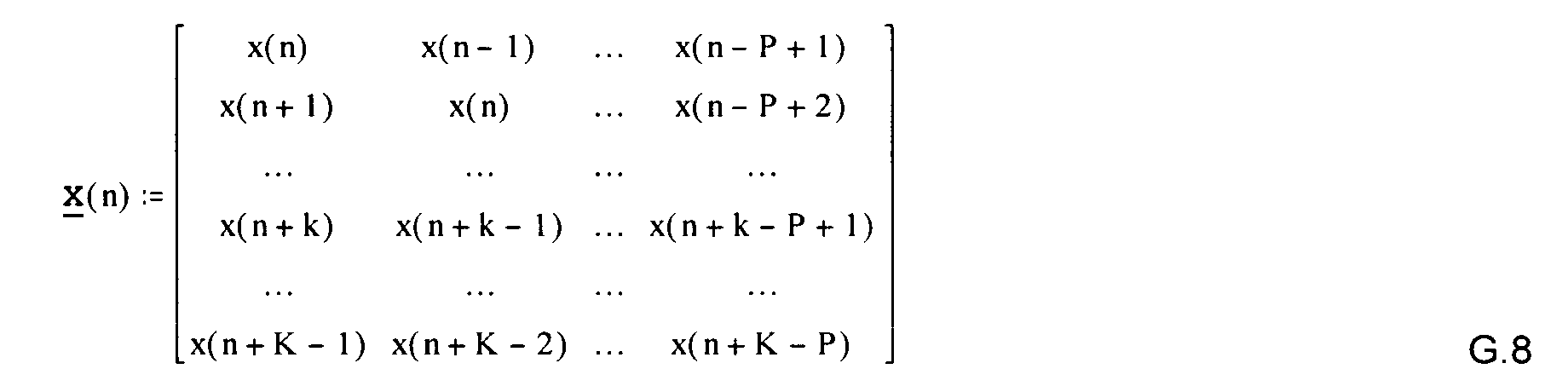
- the matrix x is called the data matrix (dimension: K * P, K> P). In many cases, x will be "long and narrow" because K >> P can be.
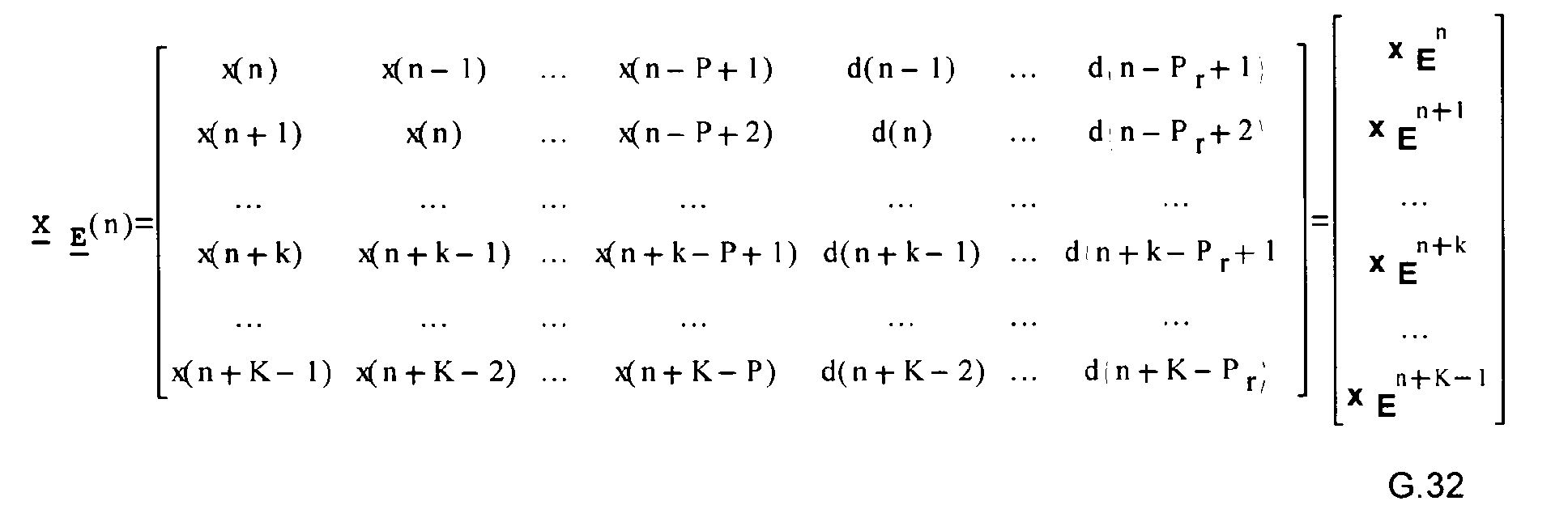
- the present invention extends the synthesis of a FIR filter to a more general IIR filter synthesis, but not in a conventional manner, but using the "equation error" method. This enables, instead of the data matrix X according to equation G.8 -
- Adaptive filters can be used to model, ie to imitate the dynamic behavior of physical systems (unknown “black boxes”).
- a dynamic system that is, the "plant” in the sense of control technology - with one input and one output
- both the input of the unknown system and the input of the adaptive filter are driven by the same input signal.
- the task for the adaptive filter is to adapt its output signal to that of the unknown system in the sense of the smallest squares of errors. If the adaptive filter has sufficient degrees of freedom (coefficients), a good adaptation to the output signal of the black box is possible; the adaptive filter can thus be regarded as a model of the unknown system ("system identification").
- a FIR digital filter The synthesis of a FIR digital filter is usually dealt with in this context, the predetermined unit impulse response of which is optimally approximated (after adaptation) by that of an adaptive filter.
- a black box in the form of a "pseudo filter" serves as the implementation concept for the specification, which generally does not have to exist physically; N sine wave generators, in accordance with the specification, form the input signal for the pseudo and the adaptive filter.
- the output signal of the pseudo filter corresponds to the reference signal ("desired response").
- the difference between this and that of the adaptive filter represents the error signal.
- the optimal coefficient vector With the help of the "Wiener-Hopf" equation G.14, the optimal coefficient vector can be found.
- the inverse model of a system has a transfer function that is optimally adapted in a certain way to the inverse transfer function of the unknown system function. If the output signal of the unknown system (“pseudo filter”) forms the input signal for the adaptive filter, then the optimal adaptation of the output signal of the adaptive filter to the input signal of the "pseudo filter” in terms of the smallest squares of errors can be required. If the unknown system is causal, the adaptive filter should make a prediction. In many cases, however, a delayed inverse transfer function can be accepted, so that the prediction requirement for the adaptive filter is eliminated.
- P coefficients and P r - 1 (P r - 1 ⁇ 1) coefficients of the feedback path are therefore available for adapting the filter in the sense of a best adaptation to the "pseudo filter".
- this method of "simultaneous direct and inverse modeling” or “equation error modeling” does not exactly deliver the minimum of the expected value of the square of error of a conventional adaptive IIR filter.
- the adaptation of sub-blocks A (z) and B (z), in the sense of the smallest sum of the error squares of the "equation error produces very similar results in an IIR filter formed with these sub-blocks.
- This consists of the chain connection of the existing forward path A (z) with a feedback loop, which B (z) - as indicated in the bottom right of FIG. 2 - takes into account by copying the coefficients and which then supplies the output signal of the IIR filter.
- the delay block with (with the smallest possible delay) z -m ensures minimum phase for 1-B (z).
- the method according to Widrow, B., Stearns, S. "Adaptive Signal Processing”, which is characterized by the idea of "simultaneous direct and inverse modeling”, can be structurally reshaped so that the connection to the optimal filter problem according to FIG. 1 becomes clear.
- the structure according to FIG. 2 found in this way is used in the generalized method according to the invention, but, as explained later, is adapted recursively and with the shortest possible learning time.
- this difference in the designation of the elements of the coefficient vector that model A (z) of the pseudo filter is correct with h A (0), h A instead of with a 0 , a 1 , ..., a P - 1 (1), ..., h A (P - 1) is taken into account and for those who model B (z), instead of using b 1 , b 2 , ..., b P r - 1 with h B (1), h B (2), ..., h B (P r - 1); P r - 1 ⁇ 1.
- the goal is to find the "best unit impulse response vector" h Eopt (n).
- h B (P r -1)) T minimized - thus h A (k) ⁇ a k , h B (k) ⁇ bk according to K + P + P r -sampled values, it is sufficient when using the method according to the invention that, starting from an optimal coefficient set h E (n) known at time n, known inverse R sE -1 and P sE , for the time n + 1, to find the solution h E (n + 1) of the 'Wiener-Hopf' equation R sE .
- H E P sE G.28a so recursively that only one 2x2 matrix must be inverted in the course of the recursive calculation, being an information matrix for the introduction of the new samples x (n + K), d (n + K-1) and for the elimination of the oldest samples x (n - P + 1), d (n - P r + 1) in the course of the formation of S E is used.
- Equation G.33 If we compare equation G.33 and the identity in the form G.35, we see that G.35 can be used to form the inverse of G.33: With the abbreviation and the 2x2 matrix s E according to G.30 (corresponds to ⁇ in G.35b) is followed by the recursive relationship and because of for the optimal coefficient vector The optimal coefficient vector h Eopt (n + 1) according to G.39, or G.25 at n + 1 is thus found, even with matrices of any size, only the inverse of the 2x2 matrix according to G.30 is necessary to use equation G.37 and finally equation G.39.
- a further feature of the invention is characterized in that for the initialization of the recursive method, the formation of inverse R sE (n start ) -1 of P sE (n start ) and the solution h Eopt (n start ) by the "Wiener-Hopf" Equation for specially selected input and reference signal profiles, which take the place of the corresponding sections of the input and reference signal profiles of the useful signals, occurs in advance for the start time n start , and from which a "sliding in” with respect to x (n) and d (n ) in the method described above so that after K samples, this leader has become completely ineffective for the further course.
Landscapes
- Filters That Use Time-Delay Elements (AREA)
Abstract
Description
Für gewöhnlich werden dabei nur Filter des Typs "FIR (Finite Impulse Response)" der Länge P verwendet, deren Koeffizienten adaptiert werden, somit die Ausgangsfolge y(n) nur als Linearkombination der Glieder der Eingangsfolge x(n), nach Gleichung G.1,


Eine rekursive Ermittlung von h opt (n + 1) aus h opt (n) erscheint daher wünschenswert und ist wegen der wenigen, sich beim Übergang von n zu n+1 ändernden Daten, mittels des in DE197 02 321 beschriebenen Algorithmus möglich.
Dieser wird gewöhnlich so definiert, daß die Wahl von h opt =h opt (n) sicherstellt, daß die Summe der Fehlerquadrate minimal wird, also:




Adaptive Filter können zum Modellieren, also zur Imitation des dynamischen Verhaltens physikalischer Systeme (unbekannte "Black Boxes") benutzt werden. Bei direkter Modellierung eines dynamischen Systems - also der Strecke ("Plant") im Sinne der Regelungstechnik - mit je einem Ein-und Ausgang, wird sowohl der Eingang des unbekannten Systems als auch der Eingang des adaptiven Filters vom selben Eingangssignal ausgesteuert. Für das adaptive Filter besteht die Aufgabe darin, sein Ausgangssignal jenem des unbekannten Systems im Sinne der kleinste Fehlerquadrate anzupassen. Besitzt das adaptive Filter ausreichende Freiheitsgrade (Koeffizienten), so ist eine gute Anpassung an das Ausgangssignal der Black Box möglich; somit kann das adaptive Filter als Modell des unbekannten Systems betrachtet werden ("System Identification"). Gewöhnlich wird in diesem Zusammenhang die Synthese eines FIR-Digitalfilters behandelt, dessen vorgegebene Einheitsimpulsantwort optimal (nach Adaption) durch jene eines adaptiven Filters angenähert ist. Dabei dient als Realisierungskonzept für die Spezifikation eine Black Box in Form eines "Pseudofilters", welches im allgemeinen nicht physikalisch existieren muß; N Sinusschwingungsgeneratoren, bilden der Spezifikation entsprechend in Summe das Eingangssignal für das Pseudo- und das adaptive Filter. Das Ausgangssignal des Pseudofilters entspricht dem Referenzsignal ("desired response"). Die Differenz zwischen diesem und dem des adaptiven Filters stellt das Fehlersignal dar. Mit Hilfe der "Wiener-Hopf" Gleichung G.14 kann der optimale Koeffizientenvektor gefunden werden.
"Direct modeling" und "inverse modeling" sind z.B. ausführlich in Widrow, B., Stearns,S. "Adaptive Signal Processing", Prentice- Hall, Englewood Cliffs, New Jersey 1985 behandelt. Besonders "Inverse modeling" hat hier deshalb Bedeutung, weil damit bekannte Probleme konventioneller adaptiver IIR-Filter, bezüglich der Fehlerflächen und Stabilität, umgangen werden können. Bei dem erfindungsgemäß verwendeten Verfahren (Fig. 2) wird simultan "direct modeling" zur Synthese des Vorwärtspfades - des nichtrekursiven Teils - des IIR-Filters und "inverse modeling" zur Synthese des Rückkopplungspfades der Systemfunktion (G.2) benutzt. Zur Adaption des Filters im Sinne einer besten Anpassung an das "Pseudofilter" stehen also P Koeffizienten und Pr - 1 (Pr - 1≥1) Koeffizienten des Feedback-Pfades zur Verfügung. Wie im zitierten Werk erläutert, liefert dieses Verfahren des "simultaneous direct and inverse modeling" oder "equation error modeling" nicht genau das Minimum des Erwartungswerts des Fehlerquadrates eines konventionellen adaptiven IIR-Filters. Praktisch erzeugt aber die Adaption der Teilblöcke A(z) und B(z), im Sinne der kleinsten Summe der Fehlerquadrate des "Equation Errors", sehr ähnliche Ergebnisse in einem mit diesen Teilblöcken gebildeten IIR-Filter. Dieses besteht aus der Kettenschaltung des bestehenden Vorwärtspfades A(z) mit einer Rückkopplungsschleife, die B(z) - wie in Fig. 2 rechts unten angedeutet - durch Kopie der Koeffizienten berücksichtigt und die dann das Ausgangssignal des IIR-Filters liefert. Der Verzögerungsblock mit (mit möglichst gering gewählter Verzögerung) z-m, sichert minimale Phase für 1-B(z).
Das, durch die Idee des "simultaneous direct and inverse modeling" geprägte, Verfahren nach Widrow, B., Stearns, S. "Adaptive Signal Processing", kann strukturell so umgeformt werden, daß die Verbindung zum Optimal-Filter-Problem nach Fig. 1 deutlich wird. Die so gefundene Struktur nach Fig. 2 wird beim erfindungsgemäß verallgemeinerten Verfahren benutzt, dabei wird aber, wie später ausgeführt, rekursiv und mit kürzestmöglicher Lernzeit adaptiert.
Gleichung G.1 entspricht somit (vergl. Fig. 2)



t=n+K-1. In Analogie zu Gleichung G.5 werden gewichtete Fehlergleichungen

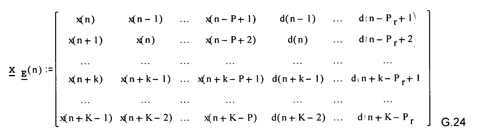

Zur erfindungsgemäßen Skalierung nach Gleichung G.21 wird die Diagonalmatrix K(n) nach G.10 verwendet, was statt G.22
Besonders nützlich ist für das praktische Verfahren, daß dieser Kunstgriff formal auch im gleitenden Datenfenster Vorteile bringt. Nach dem erfindungsgemäßen Verfahren ist es nämlich möglich - auch bei beliebig großer Koeffizientenanzahl - durch rekursive Berechnung mit der Inversen einer 2*2-Matrix auszukommen:
Um nämlich zu erreichen, daß die über n, n+1,..., N+K-1 erstreckte Summe der Quadrate skalierter Fehler nach Gleichung G.21 durch optimale Wahl der Elemente des Vektors h E (n) = (h A(0) h A(1) .... h A(P - 1) h B(1) .... h B(P r-1))T minimisiert - somit hA(k)≈ ak, hB(k)≈ bk nach K + P + P r -Abtastwerten erreicht- wird, genügt es bei Anwendung des erfindungsgemäßen Verfahrens, daß ausgehend von einem, zum Zeitpunkt n bekannten, optimalen Koeffizientensatz h E (n), bekannter Inverser R sE -1 und P sE , für den Zeitpunkt n+1, die Lösung h E (n+1) der 'Wiener-Hopf"- Gleichung R sE .h E =P sE G.28a so rekursiv zu ermitteln, daß stets nur eine 2x2-Matrix




An sich darf man die drei Matrizen B, D und C ganz beliebig wählen, wenn nur ihre Formate nach
Fig. 3 zueinander passen:
Vergleicht man Gleichung G.33 und mit der Identitätin der Gestalt G.35, so erkennt man, daß G.35 zur Bildung der Inversen von G.33 benutzt werden kann:
Mit der Abkürzung



Claims (2)
- Verfahren zur Adaption der Koeffizienten eines digitalen Filters an die Koeffizienten der Systemfunktionnach dem Equation-Error-Prinzip, dadurch gekennzeichnet, daß ein skalierter Fehler κ(n)·ε E(n) = κ(n)·d(n) - κ(n)·y E gebildet wird und die über n, n+1,..., N+K-1 erstreckte Summe der Quadrate solcher skalierter Fehler durch optimale Wahl der Elemente des Vektors h E (n)=(h A(0) h A(1) .... h A(P-1) h B(1) .... h B(P r-1)) minimisiert - somit hA(k)≈ ak, hB(k)≈ bk nach K + P + P r-Abtastwerten - wird und daß ausgehend von einem, zum Zeitpunkt n bekannten, optimalen Koeffizientensatz h E (n), bekannter Inverser R sE -1 und P sE , für den Zeitpunkt n+1, die Lösung h E (n+1) der Wiener-Hopf"- Gleichung R sE ·h E =P sE so rekursiv ermittelt wird, daß stets nur eine 2x2-Matrix
 im Verlauf der rekursiven Berechnung invertiert werden muß, wobei eine Informationsmatrix
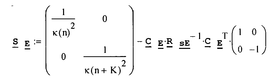 zum Einbringen der neuen Abtastwerte x(n+K), d(n+K-1) und zum Ausscheiden der ältesten Abtastwerte x(n - P + 1), d(n - P r + 1) im Verlauf der Bildung von S E verwendet wird.
- Verfahren nach Anspruch 1, dadurch gekennzeichnet, daß zur Initialisierung des rekursiven Verfahrens, die Bildung von Inverser R sE -1, von P sE und die Lösung h E der "Wiener-Hopf" Gleichung zu speziell ausgewählten Eingangs - und Referenzsignalverläufen, welche dort an Stelle der entsprechenden Ausschnitte der Eingangs - und Referenzsignalverläufe der Nutzsignale treten, vorab geschieht, und von denen ausgehend ein "Hineingleiten" bezüglich x(n) und d(n) in das Verfahren nach Anspruch 1 so erfolgt, daß nach K Abtastwerten, dieser Vorspann völlig unwirksam für den weiteren Verlauf geworden ist.
Applications Claiming Priority (2)
| Application Number | Priority Date | Filing Date | Title |
|---|---|---|---|
| AT1342002 | 2002-01-29 | ||
| AT1342002A AT413620B (de) | 2002-01-29 | 2002-01-29 | Verfahren zur koeffizientenadaption bei einem digitalen filter nach dem equation-error-prinzip |
Publications (2)
| Publication Number | Publication Date |
|---|---|
| EP1331734A2 true EP1331734A2 (de) | 2003-07-30 |
| EP1331734A3 EP1331734A3 (de) | 2004-02-25 |
Family
ID=3638163
Family Applications (1)
| Application Number | Title | Priority Date | Filing Date |
|---|---|---|---|
| EP03001775A Withdrawn EP1331734A3 (de) | 2002-01-29 | 2003-01-28 | Verfahren zur Koeffizientenadaption bei einem digitalen Filter nach dem Equation-Error-Prinzip |
Country Status (2)
| Country | Link |
|---|---|
| EP (1) | EP1331734A3 (de) |
| AT (1) | AT413620B (de) |
Cited By (1)
| Publication number | Priority date | Publication date | Assignee | Title |
|---|---|---|---|---|
| CN102821230A (zh) * | 2011-06-09 | 2012-12-12 | 索尼公司 | 图像处理装置和图像处理方法 |
Family Cites Families (1)
| Publication number | Priority date | Publication date | Assignee | Title |
|---|---|---|---|---|
| DE19702321C2 (de) * | 1997-01-23 | 2003-11-06 | Alfred Kraker | Verfahren zum adaptiven Filtern einer Eingangsfolge aus Abtastwerten und zum adaptiven linearen Kombinieren von Abtastwerten sowie adaptiver linearer Kombinierer |
-
2002
- 2002-01-29 AT AT1342002A patent/AT413620B/de not_active IP Right Cessation
-
2003
- 2003-01-28 EP EP03001775A patent/EP1331734A3/de not_active Withdrawn
Cited By (1)
| Publication number | Priority date | Publication date | Assignee | Title |
|---|---|---|---|---|
| CN102821230A (zh) * | 2011-06-09 | 2012-12-12 | 索尼公司 | 图像处理装置和图像处理方法 |
Also Published As
| Publication number | Publication date |
|---|---|
| ATA1342002A (de) | 2005-08-15 |
| AT413620B (de) | 2006-04-15 |
| EP1331734A3 (de) | 2004-02-25 |
Similar Documents
| Publication | Publication Date | Title |
|---|---|---|
| DE69332975T2 (de) | Digitales filter mit hoher genauigkeit und effizienz | |
| DE69125349T2 (de) | Einstellungsverfahren für Einrichtungen zur Auslöschung Signalzerstreuungen in Nachrichtenübertragungssystemen | |
| DE60132586T2 (de) | Verfahren und vorrichtung zur abtastratenwandlung | |
| DE68905246T2 (de) | Adaptives, digitales filter mit einem nicht rekursiven teil und einem rekursiven teil. | |
| EP0691756A1 (de) | Echokompensator mit analogen Grobkompensator und digitalem Feinkompensator | |
| DE69121825T2 (de) | Verfahren und Gerät zur Messung der Eigenschaften eines Übertragungskanals durch Sendung eines Testsignals verwendet für die Berechnung der Kanalimpulsantwort | |
| EP0974105B1 (de) | Verfahren zur mehrdimensionalen, diskreten wavelet-transformation und transformationseinheit zur durchführung des verfahrens | |
| DE60126105T2 (de) | Adaptives frequency domain filter mit partitionierten blöcken | |
| DE102004024823B4 (de) | Verfahren zur Verringerung eines Rechenaufwands in nichtlinearen Filteranordnungen sowie entsprechende Filteranordnungen | |
| DE112005001079T5 (de) | Adaptive Behelfsfilterung für Servomechanismus-Steuersysteme | |
| DE60311862T2 (de) | Entzerrer zur abtastwertweisen Entscheidungsrückmeldung im Transformationsbereich | |
| EP1331734A2 (de) | Verfahren zur Koeffizientenadaption bei einem digitalen Filter nach dem Equation-Error-Prinzip | |
| DE3333275A1 (de) | Uebertragungsanordnung fuer digitale signale | |
| DE69306893T2 (de) | Verfahren zur Bestimmung der Transmittanz einer Filterschaltung zur Umwandlung der Impulsantwort eines Filters in eine Impulsantwort mit minimaler Phase und Filter zur Durchführung des Verfahrens | |
| DE10101950C1 (de) | Entscheidungsrückgekoppelte Entzerrervorrichtung | |
| DE69602962T2 (de) | Filteranordnung mit entscheidungsrückkopplung im frequenzbereich | |
| DE60022282T2 (de) | Vorrichtung zur Bewegungskompensation für digitale Videoformat-Abwärtskonvertierung | |
| DE3702215A1 (de) | Uebertragungsanordnung fuer digitale signale | |
| DE19702321C2 (de) | Verfahren zum adaptiven Filtern einer Eingangsfolge aus Abtastwerten und zum adaptiven linearen Kombinieren von Abtastwerten sowie adaptiver linearer Kombinierer | |
| WO2000025489A1 (de) | Signaltrennungsverfahren und -anordnung für nichtlineare mischungen unbekannter signale | |
| EP1489742A2 (de) | Verfahren und Vorrichtung zur Filterung eines Signals | |
| DE10138720C1 (de) | Verfahren zur Bestimmung der optimalen Filterkoeffizienten eines adaptiven Filters durch Lösung der Wiener-Hopfgleichung | |
| DE69809367T2 (de) | Verfahren zur Stabilisierung eines fraktionierten Entzerrers in digitalen Signalempfängern | |
| EP1775833A1 (de) | Digitales Filter und Verfahren zum Entwurf digitaler Filter mittels Integrations- und Löschfilter | |
| DE4022381A1 (de) | Verwendung langer digitalfilter bei vorkommnis von abrundungsfehlern |
Legal Events
| Date | Code | Title | Description |
|---|---|---|---|
| PUAI | Public reference made under article 153(3) epc to a published international application that has entered the european phase |
Free format text: ORIGINAL CODE: 0009012 |
|
| AK | Designated contracting states |
Designated state(s): AT BE BG CH CY CZ DE DK EE ES FI FR GB GR HU IE IT LI LU MC NL PT SE SI SK TR |
|
| AX | Request for extension of the european patent |
Extension state: AL LT LV MK RO |
|
| RIN1 | Information on inventor provided before grant (corrected) |
Inventor name: KRAKER, ALFRED |
|
| PUAL | Search report despatched |
Free format text: ORIGINAL CODE: 0009013 |
|
| AK | Designated contracting states |
Kind code of ref document: A3 Designated state(s): AT BE BG CH CY CZ DE DK EE ES FI FR GB GR HU IE IT LI LU MC NL PT SE SI SK TR |
|
| AX | Request for extension of the european patent |
Extension state: AL LT LV MK RO |
|
| 17P | Request for examination filed |
Effective date: 20040621 |
|
| AKX | Designation fees paid |
Designated state(s): DE FR GB IT |
|
| STAA | Information on the status of an ep patent application or granted ep patent |
Free format text: STATUS: THE APPLICATION IS DEEMED TO BE WITHDRAWN |
|
| 18D | Application deemed to be withdrawn |
Effective date: 20070801 |