EP1331733A1 - Module de filtre de type L-C et filtre hélicoidal composé d'au moins deux tels modules - Google Patents
Module de filtre de type L-C et filtre hélicoidal composé d'au moins deux tels modules Download PDFInfo
- Publication number
- EP1331733A1 EP1331733A1 EP02360375A EP02360375A EP1331733A1 EP 1331733 A1 EP1331733 A1 EP 1331733A1 EP 02360375 A EP02360375 A EP 02360375A EP 02360375 A EP02360375 A EP 02360375A EP 1331733 A1 EP1331733 A1 EP 1331733A1
- Authority
- EP
- European Patent Office
- Prior art keywords
- filter
- capacities
- modules
- support body
- holes
- Prior art date
- Legal status (The legal status is an assumption and is not a legal conclusion. Google has not performed a legal analysis and makes no representation as to the accuracy of the status listed.)
- Granted
Links
- 239000003989 dielectric material Substances 0.000 claims abstract description 17
- 239000004020 conductor Substances 0.000 claims abstract description 15
- 239000003990 capacitor Substances 0.000 claims abstract description 10
- 239000011248 coating agent Substances 0.000 claims abstract description 7
- 238000000576 coating method Methods 0.000 claims abstract description 7
- 238000001914 filtration Methods 0.000 claims abstract description 7
- 238000004804 winding Methods 0.000 claims description 12
- 239000007787 solid Substances 0.000 claims description 8
- 239000002184 metal Substances 0.000 claims description 4
- 229920001343 polytetrafluoroethylene Polymers 0.000 claims description 3
- 239000004810 polytetrafluoroethylene Substances 0.000 claims description 3
- 239000000470 constituent Substances 0.000 claims description 2
- 238000002788 crimping Methods 0.000 claims description 2
- 230000006698 induction Effects 0.000 claims description 2
- -1 polytetrafluoroethylene Polymers 0.000 claims description 2
- 238000003466 welding Methods 0.000 claims description 2
- 230000001105 regulatory effect Effects 0.000 abstract 1
- 230000008878 coupling Effects 0.000 description 3
- 238000010168 coupling process Methods 0.000 description 3
- 238000005859 coupling reaction Methods 0.000 description 3
- 239000000463 material Substances 0.000 description 3
- 238000005481 NMR spectroscopy Methods 0.000 description 2
- 238000004519 manufacturing process Methods 0.000 description 2
- 230000035939 shock Effects 0.000 description 2
- 230000032683 aging Effects 0.000 description 1
- 230000015556 catabolic process Effects 0.000 description 1
- 238000010276 construction Methods 0.000 description 1
- 238000013016 damping Methods 0.000 description 1
- 238000010586 diagram Methods 0.000 description 1
- 230000001939 inductive effect Effects 0.000 description 1
- 230000004048 modification Effects 0.000 description 1
- 238000012986 modification Methods 0.000 description 1
- 230000003071 parasitic effect Effects 0.000 description 1
- 238000011084 recovery Methods 0.000 description 1
- 238000006467 substitution reaction Methods 0.000 description 1
Images


Classifications
-
- H—ELECTRICITY
- H01—ELECTRIC ELEMENTS
- H01P—WAVEGUIDES; RESONATORS, LINES, OR OTHER DEVICES OF THE WAVEGUIDE TYPE
- H01P1/00—Auxiliary devices
- H01P1/20—Frequency-selective devices, e.g. filters
Definitions
- the present invention relates to the field of components or passive electrical circuits, more specifically filters formed from of the association of capacities and inductances, and has for its object a module of filter composed of such components and a helical filter, in particular band pass, comprising at least two such modules.
- NMR nuclear magnetic resonance
- variable or adjustable capacity essentially comprising, on the one hand, a first element of conductive material in the form of a rod or a at least partially hollow bar, having a hole or a perforation extending axially in the body of said first element to constitute a portion of tube and, on the other hand, a second element also in conductive material in the form of a rod which can be fitted onto a variable depth in said axial hole, the depth of engagement of the second element in the first element determining the degree of coupling capacitive between them, and therefore the value of the resulting capacitance.
- the object of the present invention is in particular to respond to the less to some of the needs expressed above and to alleviate at least some of the aforementioned drawbacks.
- the present invention relates to a module for L-C type filter comprising at least two capacities and at least one inductance, characterized in that each of the capacities is constituted by a first elongated element made of a partially conductive material nested, to a determined depth, in a hole or a perforation formed in a second element made of a conductive material, connected electrically to the second elements of the other capacity or capacities or possibly common to the different capacities, at least the surfaces internal side defining said holes or perforations being covered with dielectric material, as well as the edges of the openings holes or perforations and at least parts, and preferably the all of the external surfaces of the adjoining second element (s) at said edges, and in that the winding of each inductor is carried by a support body made of a dielectric material, possibly contiguous with (x) second element (s) or with a dielectric coating covering at least partially the external face of each second element.
- Another object sought by the invention is to provide a filter helical bandpass having in particular better filtering of harmonics.
- the present invention also relates to a at least order 2 helical filter with modular structure, characterized in that it consists of the serial association of at least two modules of filter of the aforementioned type, each having filtering characteristics specific adjustable by adjusting the characteristics of at least one capacity, the different modules each being housed in a compartment electromagnetically isolated corresponding to a housing forming a cage Faraday.
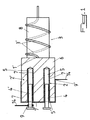
- the filter module 1 comprises at least two capacities 2, 2 'and at minus one inductance 3.
- each of the capacities 2, 2 ' is constituted by a first elongated element 4; 4 'in conductive material partially nested, to a determined depth, in a hole or a perforation 5 formed in a second element 6 made of a material conductor, electrically connected to the second elements of the other capacities or possibly common to the different capacities 2, 2 ', at minus the internal side surfaces defining said holes or perforations 5 being covered with a dielectric material 7, as well as the edges 5 ′ of the openings of the holes or perforations 5 and at least of the parts, and preferably all, of the external surfaces of the second (s) element (s) 6 adjoining said edges 5 ', and in that the winding 3' of each inductor 3 is carried by a support body 8 made of a material dielectric, possibly adjacent to the second element (s) 6 or to the dielectric coating 7 covering at least partially the external face of each second element 6 ( Figures 1 to 3).
- At least one of the capacities 2, 2 ′ is produced in the form of a variable capacity, its first elongated element 4 consisting of a screw or similar with a 4 "end portion, opposite its head, devoid of thread, and being able to slide, advantageously with a sliding contact, in the hole or the perforation 5 of the corresponding second element 3, another 4 'of said first unit elements 2 of said capacities 2, 2', preferably non-sliding, and the or one of the second element (s) 6 forming, being integral or carrying, each, one of the two terminals of connection 9, 9 'of said filter module 1.
- variable capacity 2 is notably described in the French patent application n ° 02 00770 in the name of the plaintiff, the content of which is incorporated herein by reference.
- Hollow tubes 10 made of dielectric material and provided with a flange 10 'at one of their ends are mounted by fitting in the holes or perforations 5 of the second element (s) 6 by covering thus the internal surfaces of said hole (s) or perforations 5, as well as the edges 5 'of their openings and possibly the outer surface parts adjoining these.
- the dielectric material 7 may coat a part only or all of the external surface of the second element (s) 6 and be produced either in one piece, with continuous recovery of the side walls of the holes 5, their edges 5 'at the openings of introduction of the first 4 corresponding elements and surfaces external alternatives to said edges, or in several juxtaposed parts, also producing a quasi-continuous coating 7.
- the second elements 6 each consist of a portion of metal tube inserted, snugly, into an 8 'blind hole correspondent formed in the solid support body 8 of material dielectric, the flush edges 5 ′ of the different tube portions 6 being joined together, for example by welding or crimping, with a plate of connection 11 made of a conductive material, coming into contact on the face of the support body 8 provided with blind holes 8 'for receiving the second elements 6, said plate 11 being provided with a connection terminal 9 ' in the form of a prominent lateral ear.
- a plate 12 of dielectric material covers the conductive connection plate 11 and has orifices 12 'provided 12 "radial recesses forming annular receiving seats, with cooperation of shapes, for the flanges 10 'of the hollow tubes 10 fitted into the holes or perforations 5 of the second elements 6 of capacities 2, 2 '.
- the plate 12 could for example consist of a slice cut from the support body 8.
- the cooperating assembly of flanges 10 'with the plate 12 ensures continuity of the dielectric coating 7 at this level, with the creation of a chicane guaranteeing the absence of gaps.
- the filter module 1 will advantageously include an inductance 3 (or L i, i) and two capacitors 2 (or Ci, i) and 2 '(or Ci-1, i) connected to an electrical node common 1 ', at least one 2 of said capacities 2, 2' being variable or adjustable due to a first element 4 mounted with translational faculty in the corresponding second element 6 and the first element 4 'on the other capacity 2 ', if applicable not variable, being integral with a terminal of connection 9 in the form of a strip 13 fixed to the support body in dielectric material 8 and on which the end of a line is secured connection 14.
- the strip 13 can thus serve as a support for the first element elongated 4 ', the latter can also be in the form of a screw or the like.
- said solid support body 8 has a cylindrical structure and has a helical groove 15 extending on at least part of its external surface, for housing the winding 3 'forming the induction 3, said support body 8 consisting preferably in polytetrafluoroethylene PTFE ( Figures 2 and 3).
- the latter can be advantageously mounted in strength and fitted way in at least a portion of said groove 15.
- Such an arrangement makes it possible to preserve over time the physical, electrical and electromagnetic characteristics of the inductor 3, by avoiding its deformation, by damping vibrations and shocks to which said inductor 3 could be exposed and preserving from any deformation linked to temperature variations.
- the constituent parts of said capacities 2, 2 'and of said au at least one inductor 3 are housed in a closed metal case 16, preferably parallelepiped, forming a Faraday cage and are held in the latter by attachment to two opposite side walls of the latter by means of two screws 4, 17, studs or the like, a first of said screws constituting the first elongated sliding element 4 with a variable capacity 2 and the second screw 17 securing the end opposite the dielectric support body 8 to a corresponding wall of said box 16 and ensuring the grounding of said at least one inductor, the two connection lines 14 of said module 1 extending through through holes 18, of small size, preferably substantially adjusted in size to those of connection lines 14 which pass through, these orifices being formed in the walls of said housing 16.
- the winding 3 ' of the inductor 3, mounted on the support body 8 has a variable pitch, increasing towards the second element (s) 6 of capacities 2, 2 ' or the edges 5 ′ of the apertures of the holes or perforation 5 of said one or more second element (s) 6.
- This measure further protects the 3 'winding against arcing and breakdown phenomena on the inductance side 3 exposed to the highest voltage.
- the present invention also relates to a filter helical at least of order 2 with modular structure, characterized in that it consists of the serial association of at least two filter modules 1 as described above, each with filtering characteristics specific adjustable by adjusting the characteristics of at least one capacity 2, the different modules 1 each being housed in a corresponding closed compartment 16 'of a housing 16 forming a cage Faraday, by being electromagnetically isolated from the outside and from the other modules 1 forming the filter.
- the electrical connection between two adjacent modules 1 is carried out by means of a corresponding line 14 extending through the wall 16 "separating said two adjacent modules 1 concerned, by an orifice 18 whose size is substantially adjusted to that of the section of said line 14.
- the helical filter is advantageously constituted by the series association of four filter modules 1 according to one any of claims 1 to 7, the conductors of the connectors connection 20, 20 'of said filter, mounted on the housing 16, being connected to the serial association of filter modules 1 at the level of inductors 3 of two extreme modules 1 of said chain of modules 1 forming said filter.
- the capacity 2 'of the first module 1 of the chain forming the filter will then be useless and can be deleted.
Landscapes
- Filters And Equalizers (AREA)
- Coils Or Transformers For Communication (AREA)
- Control Of Motors That Do Not Use Commutators (AREA)
Abstract
Description
Claims (12)
- Module de filtre du type L-C comprenant au moins deux capacités et au moins une inductance, caractérisé en ce que chacune des capacités (2, 2') est constituée par un premier élément allongé (4; 4') en un matériau conducteur partiellement emboíté, sur une profondeur déterminée, dans un trou ou une perforation (5) ménagé(e) dans un second élément (6) en un matériau conducteur, relié électriquement aux seconds éléments de la ou des autres capacités ou éventuellement communs aux différentes capacités (2, 2'), au moins les surfaces internes latérales définissant lesdit(e)s trous ou perforations (5) étant recouvertes d'un matériau diélectrique (7), ainsi que les bords (5') des ouvertures des trous ou perforations (5) et au moins des parties, et préférentiellement la totalité, des surfaces externes du ou des second(s) élément(s) (6) attenantes auxdits bords (5'), et en ce que l'enroulement (3') de chaque inductance (3) est porté par un corps support (8) en un matériau diélectrique, éventuellement contigu au(x) second(s) élément (6) ou au revêtement diélectrique (7) recouvrant au moins partiellement la face externe de chaque second élément (6).
- Module de filtre selon la revendication 1, caractérisé en ce que l'une (2) au moins des capacités (2, 2') est réalisée sous la forme d'une capacité variable, son premier élément allongé (4) consistant en une vis ou analogue avec une portion d'extrémité (4"), opposée à sa tête, dépourvue de filetage, et pouvant coulisser, avantageusement avec un contact glissant, dans le trou ou la perforation (5) du second élément (3) correspondant, un autre (4') desdits premiers éléments d'unité (2) desdites capacités (2, 2'), préférentiellement non coulissant, et le ou l'un des second(s)s élément(s) (6) formant, étant solidaires ou portant, chacun, une des deux bornes de branchement (9, 9') dudit module de filtre (1).
- Module de filtre selon l'une quelconque des revendications 1 et 2, caractérisé en ce que le ou chacun des second(s) élément(s) (6) est monté en totalité dans le corps support massif (8) en matériau diélectrique portant l'enroulement (3') de ladite inductance (3), ce corps massif (8) recouvrant ainsi sa ou leur surface externe, et en ce que des tubes creux (10) en matériau diélectrique et pourvus d'une collerette (10') à l'une de leurs extrémités sont montés par emboítement dans les trous ou perforations (5) du ou des second(s) élément(s) (6) en recouvrant ainsi les surfaces internes desdit(s) trous ou perforations (5), ainsi que les bords (5') de leurs ouvertures et éventuellement les parties de surface externe attenantes à ces derniers.
- Module de filtre selon l'une quelconque des revendications 1 à 3, caractérisé en ce que les seconds éléments (6) consistent chacun en une portion de tube métallique insérée, de manière ajustée, dans un trou borgne (8') correspondant ménagé dans le corps support (8) massif en matériau diélectrique, les bords (5') affleurants des différentes portions de tubes (6) étant solidarisés, par exemple par soudage ou sertissage, avec une plaquette de connexion (11) en un matériau conducteur, venant en contact sur la face du corps support (8) pourvue des trous borgnes (8') de réception des seconds éléments (6), ladite plaquette (11) étant pourvue d'une borne de branchement (9') sous la forme d'une oreille latérale proéminente.
- Module de filtre selon les revendications 3 et 4, caractérisé en ce qu'une plaquette (12) en matériau diélectrique recouvre la plaquette de connexion conductrice (11) et comporte des orifices (12') pourvus de décrochements radiaux (12") formant des sièges annulaires de réception, avec coopération de formes, pour les collerettes (10') des tubes creux (10) emboítés dans les trous ou perforations (5) des seconds éléments (6) des capacités (2, 2').
- Module de filtre selon l'une quelconque des revendications 1 à 5, caractérisé en ce qu'il comporte une inductance (3 ou L i,i) et deux capacités (2 ou Ci, i et 2' ou Ci-1, i) reliés à un noeud électrique commun (1'), l'une (2) au moins desdites capacités (2, 2') étant variable ou réglable du fait d'un premier élément (4) monté avec faculté de translation dans le second élément (6) correspondant et le premier élément (4') de l'autre capacité (2'), le cas échéant non variable, étant solidaire d'une borne de branchement (9) sous forme de lamelle (13) fixée sur le corps support en matériau diélectrique (8) et sur laquelle est solidarisée l'extrémité d'une ligne de connexion (14).
- Module de filtre selon l'une quelconque des revendications 1 à 6, caractérisé en ce que ledit corps support massif (8) présente une structure cylindrique et comporte une rainure hélicoïdale (15) s'étendant sur une partie au moins de sa surface externe, pour le logement de l'enroulement (3') formant l'induction (3), ledit corps support (8) consistant préférentiellement en du polytétrafluoroéthylène et en ce que ledit enroulement (3') est monté en force et de manière ajustée dans au moins une portion de ladite rainure (15).
- Module de filtre selon l'une quelconque des revendications 1 à 7, caractérisé en ce que les parties constitutives desdites capacités (2, 2') et de ladite au moins une inductance (3) sont logées dans un boítier métallique (16) fermé, préférentiellement parallélépipédique, formant cage de Faraday et sont maintenus dans ce dernier par fixation à deux parois latérales opposées de ce dernier par l'intermédiaire de deux vis (4, 17), goujons ou analogues, une première desdites vis constituant le premier élément allongé coulissant (4) d'une capacité (2) variable et la seconde vis (17) solidarisant l'extrémité opposée du corps support diélectrique (8) à une paroi correspondants dudit boítier (16) et assurant la mise à la masse de ladite au moins une inductance (3), les deux lignes de connexion (14) dudit module (1) s'étendant à travers des orifices traversants (18) ménagés dans les parois dudit boítier (16), de faible taille, préférentiellement sensiblement ajustées en dimensions à celles des lignes de connexion (14) qui les traversent.
- Module de filtre selon l'une quelconque des revendications 1 à 8, caractérisé en ce que l'enroulement (3') de l'inductance (3), monté sur le corps support (8), présente un pas variable, croissant en direction du ou des second(s) élément(s) (6) des capacités (2, 2') ou des bords (5') des ouvertures des trous ou perforation (5) dudit ou desdits second(s) élément(s) (6).
- Filtre hélicoïdal au moins d'ordre 2 à structure modulaire, caractérisé en ce qu'il est constitué par l'association en série d'au moins deux modules de filtre (1) selon l'une quelconque des revendications 1 à 9, présentant chacun des caractéristiques de filtrage spécifiques ajustables par le réglage des caractéristiques d'au moins une capacité (2), les différents modules (1) étant, chacun, logés dans un compartiment fermé correspondant (16') d'un boítier (16) formant cage de Faraday, en étant isolé électromagnétiquement de l'extérieur et du ou des autre(s) module(s) (1) formant le filtre.
- Filtre hélicoïdal selon la revendication 10, caractérisé en ce que la connexion électrique entre deux modules adjacents s'effectue au moyen d'une ligne (14) correspondante s'étendant à travers la paroi (16") séparant lesdits deux modules adjacents (1) concernés, par un orifice (18) dont la taille est sensiblement ajustée à celle de la section de ladite ligne (14).
- Filtre hélicoïdal selon l'une quelconque des revendications 10 et 11, caractérisé en ce qu'il est constitué par l'association en série de quatre modules de filtre (1) selon l'une quelconque des revendications 1 à 9, les conducteurs des connecteurs de raccordement (20, 20') dudit filtre, montés sur le boítier (16), étant reliés à l'association en série de modules de filtre (1) au niveau des inductances (3) des deux modules (1) extrêmes de ladite chaíne de modules (1) formant ledit filtre.
Applications Claiming Priority (2)
| Application Number | Priority Date | Filing Date | Title |
|---|---|---|---|
| FR0200831A FR2835092B1 (fr) | 2002-01-23 | 2002-01-23 | Module de filtre de type l-c et filtre helicoidal compose d'au moins deux tels modules |
| FR0200831 | 2002-01-23 |
Publications (2)
| Publication Number | Publication Date |
|---|---|
| EP1331733A1 true EP1331733A1 (fr) | 2003-07-30 |
| EP1331733B1 EP1331733B1 (fr) | 2007-09-19 |
Family
ID=8871386
Family Applications (1)
| Application Number | Title | Priority Date | Filing Date |
|---|---|---|---|
| EP02360375A Expired - Lifetime EP1331733B1 (fr) | 2002-01-23 | 2002-12-20 | Module de filtre de type L-C et filtre hélicoidal composé d'au moins deux tels modules |
Country Status (5)
| Country | Link |
|---|---|
| US (1) | US6970058B2 (fr) |
| EP (1) | EP1331733B1 (fr) |
| JP (1) | JP4245360B2 (fr) |
| DE (1) | DE60222526T2 (fr) |
| FR (1) | FR2835092B1 (fr) |
Cited By (1)
| Publication number | Priority date | Publication date | Assignee | Title |
|---|---|---|---|---|
| CN111613414A (zh) * | 2020-05-25 | 2020-09-01 | 上海岱矽集成电路有限公司 | 一种易于更换的电感 |
Families Citing this family (2)
| Publication number | Priority date | Publication date | Assignee | Title |
|---|---|---|---|---|
| CN104184577B (zh) * | 2014-09-19 | 2015-11-18 | 国网山东省电力公司济宁供电公司 | 一种链式0.7阶分数阶积分电路装置 |
| CN104505637B (zh) * | 2014-12-04 | 2016-08-24 | 李明科 | 一种用于电话线的接线装置 |
Citations (2)
| Publication number | Priority date | Publication date | Assignee | Title |
|---|---|---|---|---|
| US2913681A (en) * | 1957-06-12 | 1959-11-17 | Aladdin Ind Inc | Sleeve-tuned band-pass tuner with variable coupling |
| FR1439858A (fr) * | 1964-07-21 | 1966-05-27 | Siemens Ag | Filtre pour ondes électromagnétiques très courtes |
Family Cites Families (9)
| Publication number | Priority date | Publication date | Assignee | Title |
|---|---|---|---|---|
| BE506885A (fr) * | 1950-11-04 | |||
| US3621484A (en) * | 1970-03-05 | 1971-11-16 | Motorola Inc | Helical resonator having variable capacitor which includes windings of reduced diameter as one plate thereof |
| US3733608A (en) * | 1971-12-09 | 1973-05-15 | Motorola Inc | Circuit for coupling radio receiver and radio transmitter to a common antenna for duplex operation |
| JPS5319386B2 (fr) * | 1972-11-14 | 1978-06-20 | ||
| IT1074089B (it) * | 1976-12-16 | 1985-04-17 | Sits Soc It Telecom Siemens | Filtro passa-reiettabanda per sistemi di telecomunicazioni |
| US4374370A (en) * | 1981-03-30 | 1983-02-15 | Motorola, Inc. | Helical resonator filter |
| US4385279A (en) * | 1981-08-04 | 1983-05-24 | Motorola, Inc. | Tunable helical resonator |
| US6407651B1 (en) * | 1999-12-06 | 2002-06-18 | Kathrein, Inc., Scala Division | Temperature compensated tunable resonant cavity |
| FR2835091B1 (fr) * | 2002-01-22 | 2004-02-27 | Bruker Biospin Sa | Capacite variable, filtre et sonde rmn comportant une telle capacite |
-
2002
- 2002-01-23 FR FR0200831A patent/FR2835092B1/fr not_active Expired - Lifetime
- 2002-12-20 DE DE60222526T patent/DE60222526T2/de not_active Expired - Lifetime
- 2002-12-20 EP EP02360375A patent/EP1331733B1/fr not_active Expired - Lifetime
-
2003
- 2003-01-22 JP JP2003013473A patent/JP4245360B2/ja not_active Expired - Lifetime
- 2003-01-23 US US10/348,898 patent/US6970058B2/en not_active Expired - Lifetime
Patent Citations (2)
| Publication number | Priority date | Publication date | Assignee | Title |
|---|---|---|---|---|
| US2913681A (en) * | 1957-06-12 | 1959-11-17 | Aladdin Ind Inc | Sleeve-tuned band-pass tuner with variable coupling |
| FR1439858A (fr) * | 1964-07-21 | 1966-05-27 | Siemens Ag | Filtre pour ondes électromagnétiques très courtes |
Cited By (2)
| Publication number | Priority date | Publication date | Assignee | Title |
|---|---|---|---|---|
| CN111613414A (zh) * | 2020-05-25 | 2020-09-01 | 上海岱矽集成电路有限公司 | 一种易于更换的电感 |
| CN111613414B (zh) * | 2020-05-25 | 2021-07-20 | 上海岱矽集成电路有限公司 | 一种易于更换的电感 |
Also Published As
| Publication number | Publication date |
|---|---|
| JP4245360B2 (ja) | 2009-03-25 |
| US6970058B2 (en) | 2005-11-29 |
| DE60222526D1 (de) | 2007-10-31 |
| EP1331733B1 (fr) | 2007-09-19 |
| US20030137369A1 (en) | 2003-07-24 |
| DE60222526T2 (de) | 2008-06-26 |
| FR2835092B1 (fr) | 2004-03-05 |
| FR2835092A1 (fr) | 2003-07-25 |
| JP2003249833A (ja) | 2003-09-05 |
Similar Documents
| Publication | Publication Date | Title |
|---|---|---|
| FR2546340A1 (fr) | Filtre hyperfrequence coupe-bande accordable, de type coaxial, a resonateurs dielectriques | |
| FR2970808A1 (fr) | Dispositif d'actionneur et son procede de fabrication | |
| EP1329916B1 (fr) | Capacité variable, filtre et sonde RMN comportant une telle capacité | |
| EP1331733B1 (fr) | Module de filtre de type L-C et filtre hélicoidal composé d'au moins deux tels modules | |
| FR2680605A1 (fr) | Filtre coupe-bande en ceramique monolithique a plusieurs etages, ou les etages sont isoles les uns des autres. | |
| EP0165158A1 (fr) | Filtre diélectrique à fréquence centrale variable | |
| FR2982453A1 (fr) | Dispositif de filtrage cem sur circuit imprime | |
| CA2027885C (fr) | Cellule de filtrage et filtre correspondant | |
| CA1301836C (fr) | Dispositif de stockage d'energie electrique a tres haute tension, notamment pour generateur de marx a haute densite d'energie, et electrode pour un tel dispositif | |
| EP1607761B1 (fr) | Circuit d'alimention multifréquencielle et sonde et spectromètre RMN comportant un tel circuit | |
| EP0531189A1 (fr) | Dispositif et bloc d'alimentation haute tension pour tube à rayons X. | |
| FR2697666A1 (fr) | Parafoudre pour un dispositif de commutation isolé par un gaz. | |
| FR2725571A1 (fr) | Filtre passe-bas pour applications a haute puissance | |
| FR2464546A1 (fr) | Condensateur a connexions a micro-bandes | |
| FR2871892A1 (fr) | Circuit d'alimentation d'une bobine et sonde et spectrometre rmn comportant un tel circuit | |
| FR2487109A1 (fr) | Perfectionnements aux diviseurs de tension capacitifs moyenne tension | |
| FR2496995A1 (fr) | Filtre a elimination de bande accordable mecaniquement et circuit comportant un tel filtre | |
| FR2633118A1 (fr) | Filtre passe-bande a resonateurs dielectriques | |
| EP0072729A1 (fr) | Filtre coupe-bande à structure coaxiale | |
| FR2886450A1 (fr) | Composant a capacite distribuee variable | |
| WO1986003890A1 (fr) | Filtre passe-bande accordable sur un nombre predetermine de frequences discretes reparties dans une large bande de frequences | |
| FR2762442A1 (fr) | Bobine d'allumage pour l'alimentation d'une bougie de moteur thermique | |
| FR2820885A1 (fr) | Filtre dielectrique, duplexeur dielectrique et dispositif de telecommunications | |
| BE521287A (fr) | ||
| BE441386A (fr) |
Legal Events
| Date | Code | Title | Description |
|---|---|---|---|
| PUAI | Public reference made under article 153(3) epc to a published international application that has entered the european phase |
Free format text: ORIGINAL CODE: 0009012 |
|
| AK | Designated contracting states |
Designated state(s): AT BE BG CH CY CZ DE DK EE ES FI FR GB GR IE IT LI LU MC NL PT SE SI SK TR |
|
| AX | Request for extension of the european patent |
Extension state: AL LT LV MK RO |
|
| 17P | Request for examination filed |
Effective date: 20040121 |
|
| AKX | Designation fees paid |
Designated state(s): BE CH DE GB LI LU NL |
|
| GRAP | Despatch of communication of intention to grant a patent |
Free format text: ORIGINAL CODE: EPIDOSNIGR1 |
|
| RTI1 | Title (correction) |
Free format text: LC-TYPE FILTER MODULE AND HELICAL FILTER COMPRISING AT LEAST TWO SUCH MODULES |
|
| GRAS | Grant fee paid |
Free format text: ORIGINAL CODE: EPIDOSNIGR3 |
|
| GRAA | (expected) grant |
Free format text: ORIGINAL CODE: 0009210 |
|
| AK | Designated contracting states |
Kind code of ref document: B1 Designated state(s): BE CH DE GB LI LU NL |
|
| REG | Reference to a national code |
Ref country code: GB Ref legal event code: FG4D Free format text: NOT ENGLISH |
|
| REG | Reference to a national code |
Ref country code: CH Ref legal event code: EP |
|
| REF | Corresponds to: |
Ref document number: 60222526 Country of ref document: DE Date of ref document: 20071031 Kind code of ref document: P |
|
| REG | Reference to a national code |
Ref country code: CH Ref legal event code: NV Representative=s name: SCHNEIDER FELDMANN AG PATENT- UND MARKENANWAELTE |
|
| GBT | Gb: translation of ep patent filed (gb section 77(6)(a)/1977) |
Effective date: 20080103 |
|
| PLBE | No opposition filed within time limit |
Free format text: ORIGINAL CODE: 0009261 |
|
| STAA | Information on the status of an ep patent application or granted ep patent |
Free format text: STATUS: NO OPPOSITION FILED WITHIN TIME LIMIT |
|
| 26N | No opposition filed |
Effective date: 20080620 |
|
| PGFP | Annual fee paid to national office [announced via postgrant information from national office to epo] |
Ref country code: LU Payment date: 20141107 Year of fee payment: 13 |
|
| PGFP | Annual fee paid to national office [announced via postgrant information from national office to epo] |
Ref country code: NL Payment date: 20141128 Year of fee payment: 13 |
|
| PGFP | Annual fee paid to national office [announced via postgrant information from national office to epo] |
Ref country code: BE Payment date: 20141107 Year of fee payment: 13 |
|
| PG25 | Lapsed in a contracting state [announced via postgrant information from national office to epo] |
Ref country code: BE Free format text: LAPSE BECAUSE OF NON-PAYMENT OF DUE FEES Effective date: 20151231 |
|
| PG25 | Lapsed in a contracting state [announced via postgrant information from national office to epo] |
Ref country code: LU Free format text: LAPSE BECAUSE OF NON-PAYMENT OF DUE FEES Effective date: 20151220 |
|
| REG | Reference to a national code |
Ref country code: NL Ref legal event code: MM Effective date: 20160101 |
|
| PG25 | Lapsed in a contracting state [announced via postgrant information from national office to epo] |
Ref country code: NL Free format text: LAPSE BECAUSE OF NON-PAYMENT OF DUE FEES Effective date: 20160101 |
|
| REG | Reference to a national code |
Ref country code: CH Ref legal event code: PFA Owner name: BRUKER BIOSPIN SA, FR Free format text: FORMER OWNER: BRUKER BIOSPIN SA, FR |
|
| PGFP | Annual fee paid to national office [announced via postgrant information from national office to epo] |
Ref country code: GB Payment date: 20211222 Year of fee payment: 20 |
|
| PGFP | Annual fee paid to national office [announced via postgrant information from national office to epo] |
Ref country code: CH Payment date: 20211222 Year of fee payment: 20 |
|
| PGFP | Annual fee paid to national office [announced via postgrant information from national office to epo] |
Ref country code: DE Payment date: 20211220 Year of fee payment: 20 |
|
| REG | Reference to a national code |
Ref country code: DE Ref legal event code: R071 Ref document number: 60222526 Country of ref document: DE |
|
| REG | Reference to a national code |
Ref country code: CH Ref legal event code: PL |
|
| REG | Reference to a national code |
Ref country code: GB Ref legal event code: PE20 Expiry date: 20221219 |
|
| PG25 | Lapsed in a contracting state [announced via postgrant information from national office to epo] |
Ref country code: GB Free format text: LAPSE BECAUSE OF EXPIRATION OF PROTECTION Effective date: 20221219 |