EP1331631A1 - Optisches aufzeichnungsmedium, verfahren zur aufzeichnung auf einem optischen aufzeichnungsmedium und vorrichtung zur aufzeichnung auf einem optischen aufzeichnungsmedium - Google Patents
Optisches aufzeichnungsmedium, verfahren zur aufzeichnung auf einem optischen aufzeichnungsmedium und vorrichtung zur aufzeichnung auf einem optischen aufzeichnungsmedium Download PDFInfo
- Publication number
- EP1331631A1 EP1331631A1 EP01972663A EP01972663A EP1331631A1 EP 1331631 A1 EP1331631 A1 EP 1331631A1 EP 01972663 A EP01972663 A EP 01972663A EP 01972663 A EP01972663 A EP 01972663A EP 1331631 A1 EP1331631 A1 EP 1331631A1
- Authority
- EP
- European Patent Office
- Prior art keywords
- recording
- mark
- information
- leading edge
- trailing edge
- Prior art date
- Legal status (The legal status is an assumption and is not a legal conclusion. Google has not performed a legal analysis and makes no representation as to the accuracy of the status listed.)
- Granted
Links
Images


Classifications
-
- G—PHYSICS
- G11—INFORMATION STORAGE
- G11B—INFORMATION STORAGE BASED ON RELATIVE MOVEMENT BETWEEN RECORD CARRIER AND TRANSDUCER
- G11B7/00—Recording or reproducing by optical means, e.g. recording using a thermal beam of optical radiation by modifying optical properties or the physical structure, reproducing using an optical beam at lower power by sensing optical properties; Record carriers therefor
- G11B7/24—Record carriers characterised by shape, structure or physical properties, or by the selection of the material
- G11B7/2407—Tracks or pits; Shape, structure or physical properties thereof
- G11B7/24085—Pits
-
- G—PHYSICS
- G11—INFORMATION STORAGE
- G11B—INFORMATION STORAGE BASED ON RELATIVE MOVEMENT BETWEEN RECORD CARRIER AND TRANSDUCER
- G11B7/00—Recording or reproducing by optical means, e.g. recording using a thermal beam of optical radiation by modifying optical properties or the physical structure, reproducing using an optical beam at lower power by sensing optical properties; Record carriers therefor
- G11B7/004—Recording, reproducing or erasing methods; Read, write or erase circuits therefor
- G11B7/0045—Recording
- G11B7/00456—Recording strategies, e.g. pulse sequences
-
- G—PHYSICS
- G11—INFORMATION STORAGE
- G11B—INFORMATION STORAGE BASED ON RELATIVE MOVEMENT BETWEEN RECORD CARRIER AND TRANSDUCER
- G11B7/00—Recording or reproducing by optical means, e.g. recording using a thermal beam of optical radiation by modifying optical properties or the physical structure, reproducing using an optical beam at lower power by sensing optical properties; Record carriers therefor
- G11B7/007—Arrangement of the information on the record carrier, e.g. form of tracks, actual track shape, e.g. wobbled, or cross-section, e.g. v-shaped; Sequential information structures, e.g. sectoring or header formats within a track
- G11B7/00736—Auxiliary data, e.g. lead-in, lead-out, Power Calibration Area [PCA], Burst Cutting Area [BCA], control information
-
- G—PHYSICS
- G11—INFORMATION STORAGE
- G11B—INFORMATION STORAGE BASED ON RELATIVE MOVEMENT BETWEEN RECORD CARRIER AND TRANSDUCER
- G11B7/00—Recording or reproducing by optical means, e.g. recording using a thermal beam of optical radiation by modifying optical properties or the physical structure, reproducing using an optical beam at lower power by sensing optical properties; Record carriers therefor
- G11B7/12—Heads, e.g. forming of the optical beam spot or modulation of the optical beam
- G11B7/125—Optical beam sources therefor, e.g. laser control circuitry specially adapted for optical storage devices; Modulators, e.g. means for controlling the size or intensity of optical spots or optical traces
- G11B7/126—Circuits, methods or arrangements for laser control or stabilisation
- G11B7/1267—Power calibration
-
- G—PHYSICS
- G11—INFORMATION STORAGE
- G11B—INFORMATION STORAGE BASED ON RELATIVE MOVEMENT BETWEEN RECORD CARRIER AND TRANSDUCER
- G11B7/00—Recording or reproducing by optical means, e.g. recording using a thermal beam of optical radiation by modifying optical properties or the physical structure, reproducing using an optical beam at lower power by sensing optical properties; Record carriers therefor
- G11B2007/0003—Recording, reproducing or erasing systems characterised by the structure or type of the carrier
- G11B2007/0009—Recording, reproducing or erasing systems characterised by the structure or type of the carrier for carriers having data stored in three dimensions, e.g. volume storage
- G11B2007/0013—Recording, reproducing or erasing systems characterised by the structure or type of the carrier for carriers having data stored in three dimensions, e.g. volume storage for carriers having multiple discrete layers
-
- G—PHYSICS
- G11—INFORMATION STORAGE
- G11B—INFORMATION STORAGE BASED ON RELATIVE MOVEMENT BETWEEN RECORD CARRIER AND TRANSDUCER
- G11B7/00—Recording or reproducing by optical means, e.g. recording using a thermal beam of optical radiation by modifying optical properties or the physical structure, reproducing using an optical beam at lower power by sensing optical properties; Record carriers therefor
- G11B7/24—Record carriers characterised by shape, structure or physical properties, or by the selection of the material
- G11B7/2403—Layers; Shape, structure or physical properties thereof
- G11B7/24035—Recording layers
- G11B7/24038—Multiple laminated recording layers
Definitions
- the present invention relates to an optical recording medium and a recording and reproducing apparatus capable of recording or reproducing signals of high density by irradiating a plurality of thin recording films formed on a substrate with a high energy beam such as laser beam.
- rewritable optical recording media include the phase change optical recording medium having a disk-shaped substrate and an overlaying information layer such as a thin chalcogenide film using Te or Se as the base such as Ge-Sb-Te or In-Se, or a semimetallic thin film such as In-Sb.
- a magneto-optical recording medium having a thin metal film of Fe-Tb-Co or the like as an information layer is also known.
- a write-once optical recording medium using a dye material is also known.
- phase change optical recording medium for example, an information layer composed of the phase change material is momentarily irradiated with a laser beam focused in a light spot of a sub-micron order size, and the irradiated area is locally heated up to a specified temperature.
- the irradiated area When heated over a crystallization temperature, the irradiated area is transited from amorphous state to crystalline state, and when further heated over a melting point to be fused and then quenched, it is transited to amorphous state.
- Either the amorphous state or the crystalline state is defined as recorded state or erased state (unrecorded state), and by forming in a pattern corresponding to the information signal, reversible information recording or erasing may be realized.
- the optical characteristic of crystalline state is different from the optical characteristic of amorphous state, and by making use of this difference, the signal can be reproduced by detecting optically as a reflectivity change or a transmissivity change.
- a magneto-optical recording thin film is irradiated with a focused laser beam, and is locally heated to a specified temperature.
- a magnetic field By applying a magnetic field simultaneously when heating, the direction of magnetization of the magneto-optical recording thin film is reversed depending on the information, so that the information can be recorded or erased.
- mark length recording As a high density data recording method on an optical recording medium, mark length recording is known.
- mark length recording various mark lengths are recorded between various space lengths, and recorded information is assigned in both mark length and space length.
- other proposed optical recording medium in order to increase the capacity of the optical recording medium outstandingly, a plurality of information layers are provided, and a laser beam is irradiated from one side, and information is recorded or rewritten in each information layer.
- the amorphous region When recorded in a phase change recording medium by the mark length recording method, the amorphous region is defined as a mark, and the crystalline region as a space.
- the length of the marks and spaces to be recorded In order to record at higher density in this recording medium, the length of the marks and spaces to be recorded must be shortened. However, when the space length is shorter, the heat at the trailing edge of the recorded mark has an effect on temperature rise at the leading edge of the mark to be recorded next, or the heat at the leading edge of the mark recorded next has an effect on the cooling process of the preceding mark, that is, so-called heat interference occurs. By this heat interference, the edge position of the leading edge or trailing edge of the recording mark is deviated from the proper position, and the bit error rate is deteriorated on reproduction.
- each information layer must be irradiated with a proper quantity of laser beam.
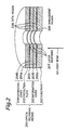
- a laser beam 901 may be irradiated to the second information layer which is at the remoter side from the irradiation direction of the laser beam 901, and may be returned to the incident side to reproduce the information.
- the transmissivity of the laser beam 901 passing through a protection layer 903, the first information layer 904 and a protection layer 905 at the side closer to the incident side of the laser beam 901 is generally designed to be higher than about 50%.
- the protection layer 903 and protection layer 905 which are thin film adjacent to the first information layer 904 are made of nonmetallic transparent layers.
- a reflection layer 910 made of a metal material is disposed adjacently to the second information layer 908.
- an optical recording medium includes a substrate, a protection plate, and a plurality of information layers sandwiched between the substrate and the protection plate.
- the plurality of information layers are for recording information signals as a length of mark and a length of a space between two marks.
- the mark is formed when irradiated by light received through the substrate.
- the plurality of information layers have a management region recording a leading edge recording condition and a trailing edge recording condition.
- the leading edge recording condition is used to change a start position for forming a leading edge of the mark, the leading edge recording condition is depending on which information layer is recorded.
- the trailing edge recording condition is used to change a recording end position for forming a trailing edge of the mark, the trailing edge recording condition is depending on which information layer is recorded.
- the leading edge recording condition may include a condition depending on the length of the mark and the length of the space preceding the mark
- the trailing edge recording condition may include a condition depending on the length of the mark and the length of the space succeeding the mark.
- the leading edge recording condition and the trailing edge recording condition may include a condition of whether data have been recorded or not in one of the information layers positioned at light incident side.
- the management region may be provided in one of the plurality of information layers.
- the management region may be provided in one of the information layers at light incident side.
- each of the plurality of information layers has a identifier for information layer.
- each of the plurality of information layers may have a recording identifier on whether data have been recorded or not therein. These recording identifier may be recorded in the management region.
- the optical recording medium includes a substrate, a protection plate, and a plurality of information layers sandwiched between the substrate and the protection plate.
- the plurality of information layers are for recording information signals as a length of a mark and a length of a space between two marks.
- the mark is formed when irradiated by light received through the substrate.
- the plurality of information layers have a learning region provided for leading edge position learning for determining an optimum value of recording start position used for forming the leading edge of the mark, and trailing edge position learning for determining an optimum value of the recording end position for forming the trailing edge of the mark to be recorded.
- each of the plurality of information layers may have the learning region.
- the optimum value of the recording start position and that of the recording end position may include an information on information layer to be recorded, the length of mark, and the length of the space preceding and succeeding the marks.
- the plurality of information layers may have a recording region for recording the optimum values of the recording start position and recording end position obtained by the learning.
- it may further include another learning region for learning the leading edge position and the trailing edge position when the information layer at light incident side of the information layer to be recorded includes recorded data and when it does not include recorded data.
- a recording method of optical recording medium for recording information signals in an information layer as a length of mark and a length of a space between two marks.
- the mark is formed when irradiated by light received trough the information layer.
- the recording method includes setting a leading edge starting condition, setting a trailing edge starting condition, and recording information signals by forming marks when irradiated by light received through the information layer.
- the leading edge starting condition may be used to change a recording start position for forming a leading edge of the mark depending on the length of the mark, the length of the space preceding the mark, and the information layer to be recorded.
- the trailing edge starting condition may be used to change the recording end position for forming a trailing edge of the mark depending on the length of the mark, the length of the space succeeding the mark, and the information layer to be recorded.
- the information signal is recorded by forming marks when irradiated by light received through the information layer. This recording is performed after setting a leading edge starting condition and setting a trailing edge starting condition.
- the recording start and end positions may be changed for recording depending on a recorded or unrecorded state of the upper information layer positioned at light incident side.
- the recording start position may be set as a position between the recording start positions in unrecorded state and in recorded state
- the recording end position may be set as a position between the recording end positions in unrecorded state and in recorded state.
- the recording start position and recording end position may be corrected based on quantity of light reflected from the upper information layer positioned at light incident side of the information layer to be recorded.
- a recording method of optical recording medium for recording information signals as a length of a mark and a length of a space between two marks.
- the mark is formed when irradiated by light received.
- the recording method includes, prior to recording the information, learning a leading edge for determining an optimum value of recording start position for forming the leading edge of the mark, and a step of learning a trailing edge for determining an optimum value of recording end position for forming the trailing edge of the mark.
- Learning the leading edge for determining an optimum value of recording start position is performed by trial writing of the marks by changing the information layer to be recorded, the length of the mark, and the length of the space preceding the mark.
- Learning the trailing edge for determining an optimum value of recording end position is performed by trial writing of the marks by changing the information layer to be recorded, the length of the mark, and the length of the space succeeding the mark.
- it may further includes selecting at least two information layer out of the plurality of information layers, executing leading edge learning and trailing edge learning, and calculating optimum values of the recording start position and the recording end position of information layer other than the information layers, on the basis of the learning results at the leading edge learning and trailing edge learning.
- the optimum value of the recording start position and the recording end positions obtained as a result of learning at the leading edge learning step and trailing edge learning step may be recorded in the plurality of information layers.
- the optimum value of the recording start position and the optimum value of the recording end position obtained as a result of learning at the leading edge learning step and trailing edge learning step may be recorded in a storage device provided in a recording apparatus for the optical recording medium.
- an information about the leading edge recording condition and the information about the trailing edge recording condition recorded in the management region may be used as initial values at the leading edge learning and at the trailing edge learning.
- leading edge learning and trailing edge learning may be executed when detecting a change in recorded state of the upper information layer positioned at light incident side of the information layer to be recorded.
- leading edge learning and trailing edge learning may be executed when detecting a change in the quantity of light reflected from the information layer to be recorded.
- a recording apparatus of optical recording medium having a plurality of information layers for recording information signals as a length of a mark and a length of a space between two marks.
- the mark is formed when irradiated by light received through the information layer.
- the recording apparatus includes a layer detector circuit, a basic pulse generator, a data length detector, a pulse synthesizer, and a laser driver.
- the layer detector circuit detects which one of the plurality of information layers is an information layer to be recorded.
- the basic pulse generator generates a pulse of a predetermined width at a leading edge position of a mark to be formed, pulse at the middle of the mark, and pulse of a predetermined width at a trailing edge position of the mark.
- the data length detector is composed of a recording mark detector circuit detecting the length of the mark, a preceding space detector circuit detecting the length of a space preceding the mark, a succeeding mark detector circuit detecting the length of a mark succeeding the mark, and a succeeding space detector circuit detecting the length of a space succeeding the mark.
- the timing controller is composed of a leading edge pulse delay circuit generating a delayed leading edge pulse by setting the delay amount of the leading edge pulse from the output signals of the recording mark detector circuit, preceding space detector circuit and layer detector circuit, and a trailing edge pulse delay circuit generating a delayed trailing edge pulse by setting the delay amount of the trailing edge pulse from the output signals of the recording mark detector circuit, succeeding space detector circuit and layer detector circuit.
- the pulse synthesizer forms a recording pulse by synthesizing the delayed leading edge pulse signal, intermediate pulse signal, and delayed trailing edge pulse signal.
- the laser driver modulates the intensity of the beam on the basis of the recording pulse.
- a timing controller composed of a recording identifying circuit, a leading edge pulse delay circuit, and a trailing edge pulse delay circuit.
- the recording identifying circuit detects the recorded state of the upper information layer positioned at light incident side of the information layer to be recorded.
- the leading edge pulse delay circuit generates a delayed leading edge pulse by setting the delay amount of the leading edge pulse from the output signals of the recording mark detector circuit, the preceding space detector circuit, said layer detector circuit, and the recording identifying circuit.
- the trailing edge pulse delay circuit generates a delayed trailing edge pulse by setting the delay amount of the trailing edge pulse from the output signals of the recording mark detector circuit, the succeeding space detector circuit, the layer detector circuit, and the recording identifying circuit.
- it may further include selector selecting the delay amount of leading edge pulse and delay amount of trailing edge pulse, from the leading edge starting information and trailing edge starting information recorded in the management region, according to the identifying result of the layer detector circuit.
- it may further include selector selecting the delay amount of leading edge pulse and delay amount of trailing edge pulse, from the leading edge starting information and trailing edge starting information recorded in the management region, according to the identifying result of the recording identifying circuit.
- it may further include a detector detecting the quantity of reflected light of the information layer to be recorded. Then, the delay amount of leading edge pulse and delay amount of trailing edge pulse may be determined based on the detecting result obtained by the reflected light quantity detector.
- the layer detector circuit may detect the layer identifier for identifying the information layer.
- the recording identifying circuit may detect the recording identifier for distinguishing whether the information layer is in recorded state or in unrecorded state.
- a recording apparatus of optical recording medium having a plurality of information layers for recording information signals as a length of a mark and a length of a space between two marks.
- the mark is formed when irradiated by light received through the information layer.
- the recording apparatus includes a layer detector, a leading edge learning means, and a trailing edge learning means.
- the layer detector detects which one of the plurality of information layers is the information layer to be recorded.
- the leading edge learning means determines an optimum value of delay amount of leading edge pulse depending on a position of the information layer to be recorded, a length of a mark, and a length of a space preceding the mark.
- the trailing edge learning means determines an optimum value of delay amount of trailing edge pulse depending on the position of the information layer to be recorded, a length of the mark, and the length of a space succeeding a recording mark.
- it may further include operating means for operating the leading edge learning means and trailing edge learning means by selecting at least two information layers out of the plurality of information layers, and calculating the optimum value of recording start position and the optimum value of recording end position of other information layers from the operating results of the leading edge learning means and trailing edge learning means.
- it may further include learning result recording device recording the learning result information obtained from the leading edge learning means and trailing edge learning means on the optical recording medium.
- leading edge learning means and trailing edge learning means may use the leading edge recording information and trailing edge recording information recorded in the management region as initial values.
- leading edge learning means and trailing edge learning means may further calculate when detecting a change in the recorded or unrecorded state of each information layer.
- leading edge learning means and trailing edge learning means may further calculate when detecting a change in the quantity of reflected light in the information layer to be recorded.
- the optical recording medium having a plurality of information layers in the case of mark length recording at high density, an independent recording condition can be set in each recording layer. Therefore, in all information layers, jitter of signals when recording marks are reproduced can be decreased, then the bit error rate of signals can be improved. As a result, the data recording density is notably improved, then the optical recording medium can be increased in capacity.
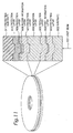
- Fig. 2 is a sectional view showing an optical recording medium used in a first embodiment of the present invention.
- an optical recording medium 201 includes a plurality of information layers 203 (203a, 203b, 203c) formed on a substrate 202, and the individual information layers are separated by separation layers 204 (204a, 204b).
- the multilayer recording layer is composed of, for example, three information layers 203.
- the substrate 202 is made of polycarbonate or other resin material, or glass. On the surface of the substrate, various patterns are formed, such as guide tracks having a specific depth for tracking of beam, pits for address, or pits depending on the management information of the optical recording medium.
- the material for composing the information layers 203a, 203b, 203c is available in two types, that is, the write-once type for recording only once, and the rewritable type for recording repeatedly.
- the write-once type recording materials include a material making use of phase change, such as Te-O and Te-O-Pd, that is, the signal is recorded by making use of difference in optical constant between amorphous state and crystalline state.
- Other is a recording material for recording by making use of change in the quantity of reflected light or quantity of transmitted light depending on diffraction by shape change of organic dye material or the like, or presence or absence of information layer.
- the rewritable type materials include a phase change material changing in phase between amorphous and crystalline state, and magneto-optical material making use of magneto-optical effect.
- phase change material such as Ge-Sb-Te or In-Sb-Te may be used.
- magneto-optical. material for example, Tb-Fe-Co may be used.
- Transparent separation layers 204a and 204b are formed among the information layers 203a, 203b, 203c.
- the separation layers 204a, 204b are required to be thin films small in light absorption at the wavelength of the irradiating light, and dielectric materials such as SiO 2 , ZnS, SiN, and AIN, or PMMA, polystyrene, and other resin materials may be used.
- the interval of the information layers 203a, 203b, 203c is set according to the allowable crosstalk of signals recorded in each information layer.
- a protection plate 205 is provided to protect the information layer.
- the material of the protection plate 205 may be same as the material of the substrate 202, or metal or other flat plate.
- marks of various lengths are recorded at intervals of various spaces by assigning recording information in both mark length and space length.
- a management region 206 is provided in a specific position of the optical recording medium 201.
- the management region 206 records, in each one of the information layers 203a, 203b, 203c, a starting information about leading edge recording condition and a starting information about trailing edge recording condition.
- the starting information about leading edge for varying the recording start position for forming the leading edge of the mark to be recorded, and depends on the length of the mark to be recorded and the length of the space preceding the mark.
- the starting information about trailing edge recording condition varies the recording end position for forming the trailing edge of the mark to be recorded, and depends on the length of the mark to be recorded and the length of the space succeeding the mark.
- the form of the management region 206 may be pits, same recording mark shape as data region, barcode, or combination thereof.
- the management region 206 is provided on one specific information layer, preferably on the information layer 203a at the closest side to the light source from the light incident side.
- the light beam may be directed to the information layer 203a to reproduce the information recorded in the management region 206 of the information layer 203a without passing through other layers. Therefore, the information may be clearly reproduced.
- layer identifiers 207 recording the information for identifying the lamination position of each information layer provided at positions close to the data region 208 on the same layer.
- the form of the layer identifiers 207 may be pits, same recording mark shape as data region, barcode, or combination thereof.
- the layer identifiers 207 may also have an information of the address for managing the position information in the plane direction. In this case, the information layer to be recorded and the information of the radial position can be identified by the layer identifiers 207 at the same time.
- the data 6 (Fig. 3 (b)) is the information to be recorded at the timing synchronized with clock 53 (Fig. 3 (a)).
- the data 6 is fed in a leading edge pulse generating circuit 2, a burst gate generating circuit 3, and a trailing edge pulse generating circuit 4, which are combined to compose a basic pulse generator1.
- a leading edge pulse 40 (Fig. 3 (c)) having one period width of clock is generated in the leading edge of Hi period of data 6 (Fig. 3 (b)).
- a bust gate signal 41 (Fig.
- a trailing edge pulse 42 (Fig. 3 (e)) having one period of clock is generated in the trailing edge of Hi period of data 6.
- the input data 6 (Fig. 3 (b)) is data in a length of clock unit, and signals like (8-16) modulation signal having Hi period or Lo period having three periods or longer of the clock 53 (Fig. 3 (a)). Then, the data having the Hi period is recorded as a mark on the optical recording medium, and the data having the Lo period is recorded as a space between two marks. That is to say, mark and space length recording. To simplify the explanation, it is supposed to change the leading edge recording condition and trailing edge recording condition by detecting space length and mark length of 3T and 4T, respectively.
- the data 6 is further fed in a preceding space detector circuit 7, a recorded mark detector circuit 8, and a succeeding space detector circuit 9, which are combined to compose a data length detector 5.
- the preceding space detector circuit 7 detects data of three-clock and four-clock width of Lo period of data 6, that is, 3T and 4T spaces, and sends a space length detection signal 43 to a leading edge starting position setting circuit 23.
- the recorded mark detector circuit 8 sends a recorded mark length detection signal 44, by detecting the length of the recorded mark, to the leading edge starting position setting circuit 23.
- a laser beam 61 is irradiated to the management region 206 on the optical recording medium 201 through an optical pick 60, and a reflected light from the management region 206 is received and converted into an electric signal by a detector 62. Then, a detection signal 37 is outputted from the detector 62.
- An amplifier 71 amplifies the detection signal 37, and outputs a reproduction signal 75 to a leading edge recording information demodulation circuit 72, a trailing edge recording information demodulation circuit 73, and a layer detector circuit 74.
- the leading edge recording information demodulation circuit 72 demodulates the leading edge recording information 38 for recording in each information layer included in the reproduction signal 75.
- the leading edge recording information 38 is stored respectively in first to third leading edge condition memory circuits 13, 14, 15 corresponding to the information layers.
- Table 1 is an examples of leading edge memory information of the leading edge condition memory circuits 13, 14, 15.
- the first leading edge condition memory circuit 13 stores leading edge starting position parameters (layer information, preceding space length, recording mark length) of the information layer 203a, and leading edge starting position setting (address (setting value), delay time d1) corresponding to the parameters.
- the second and third leading edge condition memory circuits 14, 15 store the leading edge starting position parameters of each layer and leading edge starting position setting corresponding to the parameter. In this way, the leading edge recording condition is stored in each leading edge condition memory circuit for each information layer.
- Second leading edge condition memory circuit 14 Information layer 203a 3T 3T 11 aa 4T 3T 12 ab 5T to 11T 3T 13 ac 3T 4T 14 ad 4T 4T 15 ae 5T to 11T 4T 16 af 3T 5T to 11T 17 ag 4T 5T to 11T 18 ah 5T to 11T 5T to 11T 19 ai Second leading edge condition memory circuit 14 Information layer 203b 3T 3T 21 ba 4T 3T 22 bb 5T to 11T 3T 23 bc 3T 4T 24 bd 4T 4T 25 be 5T to 11T 4T 26 bf 3T 5T to 11T 27 bg 4T 5T to 11T 28 bh 5T to 11T 5T to 11T 29 bi Third leading edge condition memory circuit 15 Information layer 203c 3T 3T 31 ca 4
- the trailing edge recording information demodulation circuit 73 demodulates the trailing edge recording information 47 for recording in each information layer included in the reproduction signal 75.
- the trailing edge recording information 47 is stored respectively in first to third trailing edge condition memory circuits 18, 19, 20 corresponding to the information layers.
- Table 2 shows an examples of trailing edge memory information of the trailing edge condition memory circuits 18, 19, 20.
- the first trailing edge condition memory circuit 18 stores trailing edge starting position parameters (layer information, succeeding space length, recording mark length) of the information layer 203a, and trailing edge starting position setting (address (setting value), delay time d2) corresponding to the parameters.
- the second and third trailing edge condition memory circuits 19, 20 store the trailing edge starting position parameters of each layer and trailing edge starting position setting corresponding to the parameters. In this way, the trailing edge recording condition is stored in each trailing edge condition memory circuit for each information layer.
- Trailing edge starting position parameter Trailing edge starting position condition Information layer Mark length Succeeding space length Address Delay time d2 (ns)
- First trailing edge condition memory circuit 18 Information layer 203a 3T 3T 41 da 3T 4T 42 db 3T 5T to 11T 43 dc 4T 3T 44 dd 4T 4T 45 de 4T 5T to 11T 46 df 5T to 11T 3T 47 dg 5T to 11T 4T 48 dh 5T to 11T 5T to 11T 49 di Second trailing edge condition memory circuit 19
- Third trailing edge condition memory circuit 20 Information layer 203a
- the layer detector circuit 74 demodulates the information layer identifying information of the layer identifier 207 from the reproduction signal 75, and identifies which the information layer focused by the laser beam 61 is any one of 203a, 203b, 203c, and outputs an identifying signal 39 for information layer. According to the identifying signal 39 for information layer, a leading edge condition changeover switch 16 selects one leading edge condition memory circuit (13, 14, 15) corresponding to the information layer to be recorded, and outputs the stored leading edge recording information 45.
- the leading edge starting position setting circuit 23 determines the parameter, on the basis of the preceding space length detection signal 43 and recording mark length detection signal 44, with respect to the leading edge recording information 45, and determines the delay time of the leading edge pulse from this parameter. For example, as explained in Table 1, when recording in the information layer 203a, the first leading edge condition memory circuit 13 is selected, and the contents of the addresses (setting values) 11 to 19 are determined, that is, the values of aa to ai as delay time d1 depending on the preceding space length and recording mark length.
- the second leading edge condition memory circuit 14 When recording in the information layer 203b, the second leading edge condition memory circuit 14 is selected, and the contents of the addresses (setting values) 21 to 29 are determined, that is, the values of ba to bi as delay time d1 depending on the preceding space length and recording mark length. Further, when recording in the information layer 203c, the third leading edge condition memory circuit 15 is selected, and the contents of the addresses (setting values) 31 to 39 are determined, that is, the values of ca to ci as delay time d1 depending on the preceding space length and recording mark length.
- the delay time d1 is supposed to be a positive value, but a negative value may be also included.
- the leading edge pulse delay circuit 24 delays the leading edge pulse 40 (Fig. 3 (c)) according to a delay signal 49 outputted from the leading edge position setting circuit 23, and outputs a delayed leading edge pulse 50 (Fig. 3 (f)).
- the leading edge pulse delay circuit 24 may vary the delayed leading edge pulse 50 in the delayed amount.
- the trailing edge starting position setting circuit 25 determines the parameter, on the basis of the trailing edge recording information 48, recording mark length detection signal 44, and succeeding space length detection signal 46, and determines the delay time of the trailing edge pulse from this parameter. For example, as explained in Table 2, when recording in the information layer 203a, the first trailing edge condition memory circuit 18 is selected, and the contents of the addresses (setting values) 11 to 19 are determined, that is, the values of da to di as delay time d2 depending on the succeeding space length and recording mark length.
- the second trailing edge condition memory circuit 19 When recording in the information layer 203b, the second trailing edge condition memory circuit 19 is selected, and the contents of the addresses (setting values) 21 to 29 are determined, that is, the values of ea to ei as delay time d2 depending on the succeeding space length and recording mark length. Further, when recording in the information layer 203c, the third trailing edge condition memory circuit 20 is selected, and the contents of the addresses (setting values) 31 to 39 are determined, that is, the values of fa to fi as delay time d2 depending on the succeeding space length and recording mark length.
- the delay time d2 is supposed to be a positive value, but a negative value may be also included.
- the trailing edge pulse delay circuit 26 delays the trailing edge pulse 42 (Fig. 3 (e)) according to a delay signal 51 outputted from the trailing edge position setting circuit 25, and outputs a delayed trailing edge pulse 52 (Fig. 3 (g)).
- the trailing edge pulse delay circuit 26 may vary the delayed trailing edge pulse 52 in the delayed amount.
- an AND gate 29 operates logical product AND between burst gate signal 41 (Fig. 3 (d)) and clock 53 (Fig. 3 (a)), and outputs an intermediate pulse 54 (Fig. 3 (h)).
- burst gate is not generated.
- an OR gate 30 operates logical sum OR of delayed leading edge pulse 50, delayed trailing edge pulse 52, and intermediate pulse 54, and generates a recording pulse 28 (Fig. 3 (i)).
- a laser drive unit 31 drives a laser unit 32 according to the recording pulse 28.
- the laser unit 32 emits light with a bias power by a driving current by a bias current source 33.
- a recording current source 34 is connected, and when the current of the recording current source 34 is turned on or off by a switch 35, the laser unit 32 is switched between the peak power and bias power.
- the recording pulse 28 is entered by the switch 35, the light emission strength of the laser unit 32 is modulated between the peak power and bias power, and a luminance waveform (Fig. 3 (j)) is outputted.
- a luminance waveform Fig. 3 (j)
- the optical recording apparatus of the embodiment can record the mark recording start position and recording end position as marks and spaces corresponding to desired data in each desired information layer. Accordingly, it can decrease mark distortion due to heat interference caused by heating, cooling condition, and enhancement of density differing in each information layer, and hence decrease the jitter of signal when reproducing the recording mark of each recording layer. As a result, in each information layer of the optical recording medium having a plurality of information layers, signals can be recorded at small bit error rate.
- the information layer to be recorded is identified by the information of the layer identifier 207, but the information layer may be also identified by the difference in the quantity of reflected light from each information layer.
- the layer detector circuit 74 can identify which information layer is to be recorded by the magnitude of the signal level of the detection signal 37, so that the structure of the layer detector circuit 74 may be simplified.
- the information layer may be also identified by the address having the position information exposed to light.
- a uniform address is set in all plurality of information layers.
- a different address may be set in each information layer in the sector address provided in each sector in the information layer.
- the demodulated address information parallelising between the address and information layer, the information layer as reproducing can be specified.
- the addresses may be set corresponding to the number of layers.
- the delay amount of the space is set to the specific value. If a space having a length longer than 5T will be used, any delay of leading edge pulse and trailing edge pulse for all space lengths are controlled so that the bit error rate will be improved.
- the delay is controlled according to the result of detection. Furthermore, detecting the preceding and succeeding mark lengths, the length of space preceding the preceding mark, and the length of space succeeding the succeeding mark, then the delay of leading edge pulse and trailing edge pulse may be controlled according to this detection result. Thus, by preliminarily detecting the preceding and succeeding mark lengths or preceding and succeeding space lengths in a wider range, the bit error rate may be further improved.
- the recording start position and recording end position of the recording marks are determined, but by fixing the succeeding edge position of the leading edge pulse and delaying the leading edge pulse start edge position, the start edge position of the trailing edge pulse may be fixed and the trailing edge pulse end edge position may be delayed and controlled.
- a second embodiment of the present invention is explained below.
- the transmissivity of the information layer varies depending on whether the information layer of the light source layer is in recorded state or unrecorded state. Accordingly, the intensity of the laser beam reaching these information layers varies, and the recording condition at the leading edge and trailing edge may be changed.
- the independent leading edge recording condition and trailing edge recording condition are set depending on the recorded state of each layer closer to the light source side than the information layer to be recorded.
- FIG. 5 is a sectional view of an optical recording medium.
- An optical recording medium 501 includes a substrate 202, an information layer 203, a separation layer 204, a protection plate 205, and a layer identifier 207, and the same one as in the first embodiment may be used.
- the information layer 203 includes recording identifiers 502 (502a, 502b, 502c) identifying whether the recorded state or unrecorded state of the information layers 203a, 203b, 203c.
- the form of the recording identifier 502 may be same recording mark shape as data region, barcode, or combination thereof.
- the management region 206 includes, in addition to those in the first embodiment, the information of leading edge recording condition and trailing edge recording condition, depending on the recorded state of the information layer at light incident side of each information layer. That is, the information layer 203b has the information relating to two kinds of recording condition of the information layer 203a, and the information layer 203c has the information relating to four kinds of recording condition of the information layers 203a, 203b.
- Fig. 4 is similar to the block diagram of Fig. 1, except that the configuration of the leading edge condition selector, trailing edge condition selector, and demodulation unit is different.
- a detection signal 37 from the optical recording medium 501 is amplified in an amplifier 71, and a reproduction signal 75 is outputted.
- a leading edge recording condition demodulation circuit 432 demodulates the leading edge recording information 440 contained in the reproduction signal 75.
- the leading edge recording information 440 is classified in seven types according to the information layer and recording condition.
- the leading edge recording information 440 having the seven types are respectively outputted in first leading edge condition memory circuit 402 to seventh leading edge condition memory circuit 408.
- Table 3 shows the contents recorded in the first leading edge condition memory circuit 402 to seventh leading edge condition memory circuit 408.
- First leading edge condition memory circuit 402 Information layer 203a - 3T 3T 11 aa 4T 3T 12 ab 5T to 11T 3T 13 ac 3T 4T 14 ad 4T 4T 15 ae 5 ⁇ 11T 4T 16 af 3T 5 to 11T 17 ag 4T 5 to 11T 18 ah 5 ⁇ 11T 5 to 11T 19 ai Second leading edge condition memory circuit 403 Information layer 203b Information layer 203a unrecorded 3T 3T 21 baa 4T 3T 22 bba (omitted) (omitted) (omitted) (omitted) 5 ⁇ 11T 5 ⁇ 11T 29 bia Third leading edge condition memory circuit 404 Information layer 203b Information layer 203a recorded 3T 3T 21 bab 4T 3T 22 bbb (omitted) (omitted) (omitted) (omitted)
- the contents recorded in the first leading edge condition memory circuit 402 are the leading edge starting position setting (address (setting value), delay time d1) corresponding to the leading edge starting position parameters (layer information, preceding space length, recording mark length) when recording in the information layer 203a.
- the contents recorded in the second leading edge condition memory circuit 403 are the leading edge starting position setting (address (setting value), delay time d1) corresponding to the leading edge starting position parameters (layer information, preceding space length, recording mark length) when recording in the information layer 203b and when the incident side recording layer 203a is in unrecorded state.
- the contents recorded in the third leading edge condition memory circuit 404 are the leading edge starting position setting (address (setting value), delay time d1) corresponding to the leading edge starting position parameters (layer information, preceding space length, recording mark length) when recording in the information layer 203b and when the incident side recording layer 203a is in recorded state.
- the contents recorded in the fourth to seventh leading edge condition memory circuits 405, 406, 407, 408 are the leading edge starting position setting (address (setting value), delay time d1) corresponding to the leading edge starting position parameters (layer information, preceding space length, recording mark length) when recording in the information layer 203c and in four states, that is, when the two recording layers 203a, 203b positioned at light incident side are in recorded state and unrecorded state, respectively.
- the reproduction signal 75 is outputted to the recording identifying circuit 434.
- the recording identifying circuit 434 demodulates the recording identifying information from the reproduction signal 75, and identifies whether the information layers 203a, 203b are in recorded state or unrecorded state, and outputs a recording identifying signal 442.
- the second layer leading edge recording condition changeover switch 409 selects either the leading edge condition memory circuit 403 or 404 according to the recording identifying signal 442, and outputs leading edge recording information 443.
- the third layer leading edge recording condition changeover switch 410 selects any one of the leading edge condition memory circuits 405 to 408 according to the recording identifying signal 442, and outputs leading edge recording information 444.
- the leading edge condition changeover switch 16 operates same as in the first embodiment, and any one of the first layer leading edge information 445, second layer leading edge information 443, and third layer leading edge information 444 is selected according to the information layer identifying signal, and leading edge information 45 is outputted. By this operation, depending on the recorded state of the information layer to be recorded and each information layer at light incident side, a delayed leading edge pulse varied in the delay amount can be outputted.
- a trailing edge recording condition demodulation circuit 433 demodulates the trailing edge recording information 441 contained in the reproduction signal 75.
- the trailing edge recording information 441 are classified in seven types by the information layer and recording condition.
- the trailing edge recording information 441 are outputted in first trailing edge condition memory circuit 420 to seventh trailing edge condition memory circuit 426.
- Table 4 shows the contents recorded in the first trailing edge condition memory circuit 420 to seventh leading edge condition memory circuit 426.
- Trailing edge starting position parameter Trailing edge starting position condition Information layer Recorded state of upper information layer Mark length Succeeding space length Address Delay time d2 (ns)
- First trailing edge condition memory circuit 420 Information layer 203a 3T 3T 11 da 3T 4T 12 db 3T 5T to 11T 13 dc 4T 3T 14 dd 4T 4T 15 de 4T 5 to 11T 16 df 5T to 11T 3T 17 dg 5T to 11T 4T 18 dh 5T to 11T 5T to 11T 19 di
- Second trailing edge condition memory circuit 421 Information layer 203b Information layer 203a unrecorded 3T 3T 21 eaa 4T 3T 22 eba (omitted) (omitted) (omitted) (omitted) 5T to 11T 29 eia
- Third trailing edge condition memory circuit 422 Information layer 203b Information layer 203a recorded 3T 3T 21 eab 4T 3T 22
- the contents recorded in the first trailing edge condition memory circuit 420 are the trailing edge starting position setting (address (setting value), delay time d2) corresponding to the trailing edge starting position parameters (layer information, succeeding space length, recording mark length) when recording in the information layer 203a.
- the contents recorded in the second trailing edge condition memory circuit 421 are the trailing edge starting position setting (address (setting value), delay time d2) corresponding to the trailing edge starting position parameters (layer information, succeeding space length, recording mark length) when recording in the information layer 203b and when the incident side recording layer 203a is in unrecorded state.
- the contents recorded in the third trailing edge condition memory circuit 422 are the trailing edge starting position setting (address (setting value), delay time d2) corresponding to the trailing edge starting position parameters (layer information, succeeding space length, recording mark length) when recording in the information layer 203b and when the incident side recording layer 203a is in recorded state.
- the contents recorded in the fourth to seventh trailing edge condition memory circuits 423, 424, 425 are the trailing edge starting position setting (address (setting value), delay time d2) corresponding to the trailing edge starting position parameters (layer information, succeeding space length, recording mark length) when recording in the information layer 203c and in four states, that is, when the two recording layers 203a, 203b positioned at light incident side are in recorded state and unrecorded state, respectively.
- the reproduction signal 75 is outputted to the recording identifying circuit 433.
- the recording identifying circuit 434 demodulates the recording identifying information from the reproduction signal 75, and identifies whether the information layers 203a, 203b are in recorded state or unrecorded state, and outputs a recording identifying signal 441.
- the second layer trailing edge recording condition changeover switch 427 selects either the trailing edge condition memory circuit 421 or 422 according to the recording identifying signal 441, and outputs trailing edge recording information 451.
- the third layer trailing edge recording condition changeover switch 428 selects any one of the trailing edge condition memory circuits 423 to 426 according to the recording identifying signal 441, and outputs trailing edge recording information 452.
- the trailing edge condition changeover switch 21 operates same as in the first embodiment, and any one of the first layer trailing edge information 453, second layer trailing edge information 451, and third layer trailing edge information 452 is selected according to the information layer identifying signal 39, and trailing edge information 48 is outputted.
- a delayed trailing edge pulse varied in the delay amount can be outputted.
- the optical recording medium of the embodiment can record the recording start position and recording end position of the mark depending on the information layer to be recorded, recorded state of the upper information layer at the incident side, recording mark length, and length of space preceding and succeeding the mark. Accordingly, it can compensate for the difference in the light irradiation condition caused by recorded state of the information layer at the incident side, and the jitter of the signal by reproducing the recording mark is decreased. As a result, signals of small bit error rate can be recorded in each information layer of the optical recording medium having a plurality of information layers.
- the recording identifying circuit 434 may be also designed to output the recording identifying information according to the level of the quantity of reflected light from the information layer at the light source side by estimating the quantity of reflected light from the reproduction signal when reproducing the information layer to be recorded. If recorded region and unrecorded region coexist in a passing range of incident beam of information layer at the light source side of the information layer to be recorded, the correction rate of the delay amount of the leading edge pulse and trailing edge pulse can be estimated from the level of the quantity of reflected light.
- the recording conditions of leading edge and trailing edge of each information layer can be simplified to two types.
- this embodiment proposes a method of determining optimum values by learning the leading edge position and trailing edge position of recording pulse in each information layer.
- Fig. 6 is a diagram of sectional view of optical recording medium.
- Learning regions 601 are provided in the information layers 203a, 203b, 203c for determining the optimum values of delay amount of leading edge pulse and trailing edge pulse.
- a configuration of an apparatus for recording information in an optical recording medium 501 is shown in Fig. 8, in which a leading edge delay amount change circuit 801 is added to the leading edge pulse delay circuit 24 of the timing controller 22 in Fig. 1, and a trailing edge delay amount change circuit 802 is added to the trailing edge pulse delay circuit 25.
- a laser beam is focused on the learning region 601 on the information layer 203 for learning.
- the leading edge delay amount change circuit 801 outputs a delay signal 49 changing discontinuously the delay amount depending on the combination of the recording mark and the space preceding the mark.
- the leading edge pulse delay circuit 24 outputs a delayed leading edge pulse 50 according to the delay signal 49.
- the trailing edge delay amount change circuit 802 outputs a delay signal 51 changing discontinuously the delay amount depending on the combination of the recording mark and the space succeeding the mark.
- the trailing edge pulse delay circuit 25 outputs a delayed trailing edge pulse 52 according to the delay signal 51.
- the laser beam modulated by the recording pulses according to the delayed leading edge pulse 50 and delayed trailing edge pulse 52 discontinuously changed is emitted on the information layer 203, and recording marks are formed.
- the edge interval of the recording marks and space reproducing signal formed at step 704 is measured.
- Figs. 9A to 9C are diagrams showing the relation of the reproduced signal of recording mark, delay amount, and edge interval.
- Fig. 9A shows a reproduced signal waveform of recording mark.
- the preceding edge interval of 4T mark is measured.
- the preceding edge position of 4T mark is recorded by changing discontinuously at step 704, and the leading edge interval varies corresponding to the delay amount of the leading edge pulse (Fig. 9B).
- the succeeding edge interval of 4T mark is measured.
- the succeeding edge position of 4T mark is recorded by changing discontinuously at step 704, and the trailing edge interval varies corresponding to the delay amount of the trailing edge pulse (Fig. 9C).
- Identifying step 706 is to determine the optimum delay amounts of leading edge pulse and trailing edge pulse so that the preceding edge interval and succeeding edge interval of reproduction signal may be optimum length as shown in Figs. 9B and 9C .
- Step 706 is followed by delay amount setting step 707 of storing the leading edge position set value of the learned information layer in each leading edge condition memory circuit in the leading edge condition selector 12 in Fig. 4 explained in the first embodiment.
- the trailing edge position set value of the learned information layer is stored in each trailing edge condition memory circuit in the trailing edge condition selector 17.
- step 701 to step 707 The process from step 701 to step 707 is repeatedly learned in the existing information layers. After learning from step 701 to step 707, at learning value recording step 709, the information of leading edge position set value and trailing edge position set value stored at step 707 is recorded in the management region on the optical recording medium 501. After step 709, the optical recording apparatus is in ready state waiting for recording.
- the leading edge information or trailing edge information may be set to the optimum value corresponding to the combination of the recording mark, immediately preceding space and immediately succeeding space.
- the starting value of the delay amount at delay amount change step 702 should be used as the leading edge starting position set value and trailing edge starting position set value recorded in the management region 206.
- learning is started from the interval closer to the optimum edge interval, and the learning time can be shortened by limiting the changing range of the delay amount.
- the information of the leading edge position set value and trailing edge position set value stored at delay amount setting step 707 is recorded on the optical recording medium, and in this case. Furthermore, when the optical recording medium 501 is loaded again in the optical recording apparatus, by setting the delay mount of the leading edge position and delay amount of the trailing edge position according to the recorded leading edge information and trailing edge information, it is possible to record nearly at the optimum edge interval. As a result, the learning time is further shortened, or may be even eliminated.
- learning in other information layers can be omitted.
- learning results in other information layers may be set by interpolating from the learning results of the information layers that actually carried out the learning step. In this case, it is not needed to execute learning in all information layers, and the learning time can be shortened.
- This learning may be also executed depending whether the information layer of the light incident side of the information layer to be recorded is in recorded state or unrecorded state.
- the intensity of the laser beam reaching the subsequent information layers varies, and the recording condition of each information layer changes. Since the delay amount is learned corresponding to the combination of recorded state of each information layer, optimum leading edge position set value and trailing edge position set value corresponding to the recorded state of each information layer can be set, so that more accurate learning is possible.
- a recording method of optical recording medium is explained.
- this recording method of optical recording medium as compared with the recording method of optical recording medium in the third embodiment, it includes an additional step, that is, learning step is executed in selected information layers out of the plurality of information layers, and optimum values of recording start position and recording end position about the information layers skipping the learning step are calculated on the basis of the obtained learning results.
- the learning step is executed only in selected information layers, not in all information layers, and the required time for learning step can be shortened.
- optical properties of information layers such as reflectivity, transmissivity and absorption rate, or thermal properties such as heat conduction, temperature elevation and cooling may vary continuously or discontinuously in laminated information layers.
- the optimum delay amount of other information layers can be predicted as continuously or discontinuously changing values from the learning results of the selected information layers.
- the example is the optical recording medium 501 having three information layers 203a, 203b, 203c shown in Fig. 6.
- the information layer 203a of the remotest side from the light source and the information layer 203a at the closest side to the light source are selected for learning step.
- steps 801 to 807 are substantially same as step 701 to 707 in the third embodiment.
- the time required for learning step can be shortened.
- the set value of the delay amount of the recording pulse of the information layers at intermediate positions can be set by equally distributing the set values of each delay amount from the learning result from the information layer at the light source side and the learning result from the information layer remotest from the light source.
- the learning results of two selected information layers are interpolated linearly, and the intermediate value is used as the optimum delay amount for the information layer at the intermediate position, but the method is not limited to this alone.
- learning results of recording pulses in each information layer at intermediate position are measured preliminarily, and the interpolation coefficient (interpolation formula) may be calculated from the measured results of the characteristics.
- the interpolation coefficient interpolation formula
- the learning step can be executed in a multi-layer optical recording medium of similar type.
- the interpolation coefficient is determined about the optimum delay amount of other information layer.
- the optimum delay amount of other information layer can be interpolated. That is, it is enough to execute the learning procedure only in one information layer of the two information layers, the time required for learning procedure can be shortened.
Priority Applications (1)
| Application Number | Priority Date | Filing Date | Title |
|---|---|---|---|
| EP08151066A EP1926094A1 (de) | 2000-10-05 | 2001-10-03 | Optisches Aufzeichnungsmedium, Verfahren zur Aufzeichnung auf einem optischen Aufzeichnungsmedium und Vorrichtung zur Aufzeichnung auf einem optischen Aufzeichnungsmedium |
Applications Claiming Priority (3)
| Application Number | Priority Date | Filing Date | Title |
|---|---|---|---|
| JP2000305818 | 2000-10-05 | ||
| JP2000305818 | 2000-10-05 | ||
| PCT/JP2001/008690 WO2002029791A1 (fr) | 2000-10-05 | 2001-10-03 | Support d"enregistrement optique, procede d"enregistrement sur support d"enregistrement optique et appareil d"enregistrement sur support d"enregistrement optique |
Related Child Applications (1)
| Application Number | Title | Priority Date | Filing Date |
|---|---|---|---|
| EP08151066A Division EP1926094A1 (de) | 2000-10-05 | 2001-10-03 | Optisches Aufzeichnungsmedium, Verfahren zur Aufzeichnung auf einem optischen Aufzeichnungsmedium und Vorrichtung zur Aufzeichnung auf einem optischen Aufzeichnungsmedium |
Publications (3)
| Publication Number | Publication Date |
|---|---|
| EP1331631A1 true EP1331631A1 (de) | 2003-07-30 |
| EP1331631A4 EP1331631A4 (de) | 2005-08-24 |
| EP1331631B1 EP1331631B1 (de) | 2008-04-09 |
Family
ID=18786611
Family Applications (2)
| Application Number | Title | Priority Date | Filing Date |
|---|---|---|---|
| EP01972663A Expired - Lifetime EP1331631B1 (de) | 2000-10-05 | 2001-10-03 | Optisches aufzeichnungsmedium, verfahren zur aufzeichnung auf einem optischen aufzeichnungsmedium und vorrichtung zur aufzeichnung auf einem optischen aufzeichnungsmedium |
| EP08151066A Withdrawn EP1926094A1 (de) | 2000-10-05 | 2001-10-03 | Optisches Aufzeichnungsmedium, Verfahren zur Aufzeichnung auf einem optischen Aufzeichnungsmedium und Vorrichtung zur Aufzeichnung auf einem optischen Aufzeichnungsmedium |
Family Applications After (1)
| Application Number | Title | Priority Date | Filing Date |
|---|---|---|---|
| EP08151066A Withdrawn EP1926094A1 (de) | 2000-10-05 | 2001-10-03 | Optisches Aufzeichnungsmedium, Verfahren zur Aufzeichnung auf einem optischen Aufzeichnungsmedium und Vorrichtung zur Aufzeichnung auf einem optischen Aufzeichnungsmedium |
Country Status (6)
| Country | Link |
|---|---|
| US (1) | US7193948B2 (de) |
| EP (2) | EP1331631B1 (de) |
| JP (1) | JP4185774B2 (de) |
| AU (1) | AU2001292339A1 (de) |
| DE (1) | DE60133571T2 (de) |
| WO (1) | WO2002029791A1 (de) |
Cited By (21)
| Publication number | Priority date | Publication date | Assignee | Title |
|---|---|---|---|---|
| WO2004086376A1 (ja) | 2003-03-25 | 2004-10-07 | Ricoh Company Ltd. | 光情報記録装置、情報処理装置、光情報記録媒体、光情報記録方法、プログラム及び記憶媒体 |
| WO2005031718A1 (ja) | 2003-09-30 | 2005-04-07 | Pioneer Corporation | 情報記録装置及び方法、並びに情報記録媒体 |
| EP1577884A1 (de) * | 2002-12-17 | 2005-09-21 | Mitsubishi Chemical Corporation | Optisches aufzeichnungsmedium, aufzeichnungs-/wiedergabeverfahren für optisches aufzeichnungsmedium und aufzeichnungs-/wiedergabevorrichtung |
| EP1607950A1 (de) * | 2003-03-25 | 2005-12-21 | Ricoh Company, Ltd. | OPTISCHES AUFZEICHNUNGSMEDIUM UNDb INFORMATIONSAUFZEICHNUNGSVERFAHREN |
| EP1713064A3 (de) * | 2003-07-07 | 2007-05-30 | LG Electronics Inc. | Aufzeichnungsmedium, Konfigurationsverfahren für diesbezügliche Steuerinformation, Aufzeichnungs-und/oder Wiedergabeverfahren sowie Gerät dafür |
| EP1760702A3 (de) * | 2003-08-14 | 2007-06-06 | LG Electronics Inc. | Aufzeichnungsmedium, Konfigurationsverfahren für diesbezügliche Steuerinformation, Aufzeichnungs- und Wiedergabeverfahren sowie Gerät dafür |
| EP1777701A3 (de) * | 2003-08-14 | 2007-07-11 | LG Electronics Inc. | Aufzeichnungsmedium, Konfigurationsverfahren für diesbezügliche Steuerinformation, Aufzeichnungs- und Wiedergabeverfahren sowie Gerät dafür |
| EP1808856A1 (de) * | 2003-07-09 | 2007-07-18 | LG Electronics Inc. | Aufzeichnungsmedium, Konfigurationsverfahren für diesbezügliche Plattensteuerinformation, Aufzeichnungs- und Wiedergabeverfahren sowie Gerät dafür |
| EP1868185A1 (de) * | 2005-03-31 | 2007-12-19 | Matsushita Electric Industrial Co., Ltd. | Aufzeichnungseinrichtung für optische datenträger, verfahren zum aufzeichnen von daten auf einem optischen datenträger und optischer datenträger |
| EP1509908A4 (de) * | 2002-05-31 | 2008-03-19 | Samsung Electronics Co Ltd | Mehrschichtiges optisches informationsspeichermedium und aufzeichnungs-/wiedergabeverfahren dafür |
| EP1498882A4 (de) * | 2002-04-19 | 2008-04-09 | Matsushita Electric Ind Co Ltd | Verfahren zum aufzeichnen optischer informationen, aufzeichnungseinrichtung für optische informationen und aufzeichnungsmedium für optische informationen |
| EP1924990A1 (de) * | 2005-09-15 | 2008-05-28 | Ricoh Company, Ltd. | Optisches aufzeichnungsmedium und vorrichtung zur optischen aufzeichnung |
| EP1642268B1 (de) * | 2003-07-03 | 2008-09-03 | Matsushita Electric Industrial Co., Ltd. | Aufzeichnungsverfahren, aufzeichnungsvorrichtung und aufzeichnungsmedium |
| US7460453B2 (en) | 2003-07-07 | 2008-12-02 | Lg Electronics Inc. | Recording medium, method of recording and/or reproducing speed information on a recording medium, and apparatus thereof |
| US7468936B2 (en) | 2003-08-14 | 2008-12-23 | Lg Electronics Co., Ltd. | Recording and/or reproducing methods and apparatuses |
| EP2051247A1 (de) * | 2003-07-07 | 2009-04-22 | LG Electronics Inc. | Aufzeichnungsmedium, Konfigurationsverfahren für diesbezügliche Steuerinformation, Aufzeichnungs- und/oder Wiedergabeverfahren sowie Gerät dafür |
| US7650362B2 (en) | 2003-08-14 | 2010-01-19 | Lg Electronics Inc. | Information recording medium, method of configuring version information thereof, recording and reproducing method using the same, and recording and reproducing apparatus thereof |
| US7706230B2 (en) | 2004-05-13 | 2010-04-27 | Lg Electronics, Inc. | Recording medium, read/write method thereof and read/write apparatus thereof |
| US7719934B2 (en) | 2003-07-07 | 2010-05-18 | Lg Electronics Inc. | Recording medium, method of configuring control information thereof, recording and/or reproducing method using the same, and apparatus thereof |
| US7801000B2 (en) | 2002-12-17 | 2010-09-21 | Mitsubishi Kagaku Media Co., Ltd. | Recording/reading method for an optical recording medium using an irradiating a laser beam |
| US8085636B2 (en) | 2004-07-27 | 2011-12-27 | Lg Electronics Inc. | Recording medium, method for recording control information in the recording medium, and method and apparatus for recording/reproducing data in/from the recording medium using the same |
Families Citing this family (14)
| Publication number | Priority date | Publication date | Assignee | Title |
|---|---|---|---|---|
| JP3846373B2 (ja) * | 2002-06-28 | 2006-11-15 | ヤマハ株式会社 | 光ディスク記録方法、光ディスク記録プログラム、及び光ディスク記録装置 |
| US7489620B2 (en) | 2002-08-21 | 2009-02-10 | Nec Corporation | Optical information recording and reproducing medium |
| US20040085874A1 (en) * | 2002-10-28 | 2004-05-06 | Matsushita Electric Industrial Co., Ltd. | Optical information recording medium, optical recording and reproducing method and optical recording and reproducing apparatus |
| JP2004199757A (ja) * | 2002-12-17 | 2004-07-15 | Mitsubishi Chemicals Corp | 光記録媒体,光記録媒体の記録再生方法及び光記録媒体の記録再生装置 |
| EP1986186A1 (de) * | 2002-12-20 | 2008-10-29 | Mitsubishi Kagaku Media Co., Ltd. | Aufzeichnungsverfahren für das optische Aufzeichnungsmedium |
| JP4792386B2 (ja) * | 2003-02-13 | 2011-10-12 | ダグ カーソン アンド アソシエーツ,インク. | 多層光ディスク内のトラック層の識別タグ |
| ES2359914T3 (es) * | 2003-03-25 | 2011-05-30 | Ricoh Company, Ltd. | Medio de grabación óptico y procedimiento de grabación de información. |
| JP4537781B2 (ja) * | 2004-06-30 | 2010-09-08 | パイオニア株式会社 | チルト検出装置及び方法、該チルト検出装置を備えたチルト補正装置、並びに、該チルト補正装置を備えた情報再生装置、情報記録装置及び情報記録再生装置 |
| JP2006040348A (ja) * | 2004-07-23 | 2006-02-09 | Fuji Photo Film Co Ltd | 光記録媒体及び記録方法 |
| JPWO2006049301A1 (ja) * | 2004-11-08 | 2008-05-29 | 松下電器産業株式会社 | 光情報記録媒体およびその情報記録再生方法、並びに情報記録再生装置 |
| JP4451822B2 (ja) | 2005-08-09 | 2010-04-14 | 太陽誘電株式会社 | 光記録方法、光記録装置、ワンチップcpu素子、及びコンピュータプログラム |
| US7660218B2 (en) | 2005-08-09 | 2010-02-09 | Taiyo Yuden Co., Ltd. | Optical recording method, evaluation indicator acquiring method, optical recording apparatus, micro CPU device, and computer program |
| JP2008097802A (ja) * | 2006-09-15 | 2008-04-24 | Tdk Corp | 多層光記録媒体及び多層光記録媒体への記録方法 |
| JP2012038363A (ja) * | 2010-08-03 | 2012-02-23 | Hitachi-Lg Data Storage Inc | 光ディスクおよび光ディスク装置 |
Citations (6)
| Publication number | Priority date | Publication date | Assignee | Title |
|---|---|---|---|---|
| EP0517490A2 (de) * | 1991-06-04 | 1992-12-09 | International Business Machines Corporation | Optisches Datenspeichersystem und -verfahren mit Mehrfachdatenoberfläche |
| WO1996019807A2 (en) * | 1994-12-19 | 1996-06-27 | Philips Electronics N.V. | Multilayer record carrier and device for scanning said carrier |
| EP0797193A1 (de) * | 1995-10-09 | 1997-09-24 | Matsushita Electric Industrial Co., Ltd. | Verfahren und vorrichtung zur aufnahme von optischer information |
| JPH113550A (ja) * | 1997-06-12 | 1999-01-06 | Nikon Corp | 情報記録再生装置 |
| EP0984441A1 (de) * | 1998-09-14 | 2000-03-08 | Matsushita Electric Industrial Co., Ltd. | Aufzeichnungsmedium, Aufzeichnungsgerät und Aufzeichnungsverfahren |
| EP1059630A1 (de) * | 1998-11-06 | 2000-12-13 | Matsushita Electric Industrial Co., Ltd. | Verfahren und vorrichtung zur feststellung von bedingungen auf einem aufzeichnungspuls einer optischen platte |
Family Cites Families (6)
| Publication number | Priority date | Publication date | Assignee | Title |
|---|---|---|---|---|
| JP2679596B2 (ja) | 1993-11-09 | 1997-11-19 | 松下電器産業株式会社 | ディスク記録方法およびディスク記録装置 |
| US5490126A (en) | 1993-04-07 | 1996-02-06 | Matsushita Electric Industrial Co., Ltd. | Apparatus for recording and reproducing data on a disk |
| US5756265A (en) | 1995-06-09 | 1998-05-26 | Matsushita Electric Industrial Co., Ltd. | Multilayer optical disc and method of making same |
| CN1295686C (zh) * | 1996-12-20 | 2007-01-17 | 松下电器产业株式会社 | 光记录方法 |
| JPH1166576A (ja) * | 1997-08-22 | 1999-03-09 | Nikon Corp | 情報記録再生装置 |
| JP2000293947A (ja) | 1999-04-08 | 2000-10-20 | Matsushita Electric Ind Co Ltd | 光ディスク及び光ディスク記録再生装置、方法 |
-
2001
- 2001-10-03 AU AU2001292339A patent/AU2001292339A1/en not_active Abandoned
- 2001-10-03 EP EP01972663A patent/EP1331631B1/de not_active Expired - Lifetime
- 2001-10-03 JP JP2002533284A patent/JP4185774B2/ja not_active Expired - Fee Related
- 2001-10-03 EP EP08151066A patent/EP1926094A1/de not_active Withdrawn
- 2001-10-03 DE DE60133571T patent/DE60133571T2/de not_active Expired - Lifetime
- 2001-10-03 WO PCT/JP2001/008690 patent/WO2002029791A1/ja active IP Right Grant
- 2001-10-03 US US10/148,797 patent/US7193948B2/en not_active Expired - Fee Related
Patent Citations (6)
| Publication number | Priority date | Publication date | Assignee | Title |
|---|---|---|---|---|
| EP0517490A2 (de) * | 1991-06-04 | 1992-12-09 | International Business Machines Corporation | Optisches Datenspeichersystem und -verfahren mit Mehrfachdatenoberfläche |
| WO1996019807A2 (en) * | 1994-12-19 | 1996-06-27 | Philips Electronics N.V. | Multilayer record carrier and device for scanning said carrier |
| EP0797193A1 (de) * | 1995-10-09 | 1997-09-24 | Matsushita Electric Industrial Co., Ltd. | Verfahren und vorrichtung zur aufnahme von optischer information |
| JPH113550A (ja) * | 1997-06-12 | 1999-01-06 | Nikon Corp | 情報記録再生装置 |
| EP0984441A1 (de) * | 1998-09-14 | 2000-03-08 | Matsushita Electric Industrial Co., Ltd. | Aufzeichnungsmedium, Aufzeichnungsgerät und Aufzeichnungsverfahren |
| EP1059630A1 (de) * | 1998-11-06 | 2000-12-13 | Matsushita Electric Industrial Co., Ltd. | Verfahren und vorrichtung zur feststellung von bedingungen auf einem aufzeichnungspuls einer optischen platte |
Non-Patent Citations (2)
| Title |
|---|
| PATENT ABSTRACTS OF JAPAN vol. 1999, no. 04, 30 April 1999 (1999-04-30) & JP 11 003550 A (NIKON CORP), 6 January 1999 (1999-01-06) * |
| See also references of WO0229791A1 * |
Cited By (70)
| Publication number | Priority date | Publication date | Assignee | Title |
|---|---|---|---|---|
| EP2053601A3 (de) * | 2002-04-19 | 2009-12-09 | Panasonic Corporation | Optisches Informationsaufzeichnungsverfahren und optisches Informationsaufzeichnungsmedium |
| EP2053601A2 (de) | 2002-04-19 | 2009-04-29 | Panasonic Corporation | Optisches Informationsaufzeichnungsverfahren und optisches Informationsaufzeichnungsmedium |
| EP2226797A3 (de) * | 2002-04-19 | 2010-12-01 | Panasonic Corporation | Optisches Informationsaufzeichnungsverfahren und optisches Informationsaufzeichnungsmedium |
| EP2221811A3 (de) * | 2002-04-19 | 2010-12-08 | Panasonic Corporation | Optisches Informationsaufzeichnungsverfahren und optisches Informationsaufzeichnungsmedium |
| EP1498882A4 (de) * | 2002-04-19 | 2008-04-09 | Matsushita Electric Ind Co Ltd | Verfahren zum aufzeichnen optischer informationen, aufzeichnungseinrichtung für optische informationen und aufzeichnungsmedium für optische informationen |
| EP1509908A4 (de) * | 2002-05-31 | 2008-03-19 | Samsung Electronics Co Ltd | Mehrschichtiges optisches informationsspeichermedium und aufzeichnungs-/wiedergabeverfahren dafür |
| US7801000B2 (en) | 2002-12-17 | 2010-09-21 | Mitsubishi Kagaku Media Co., Ltd. | Recording/reading method for an optical recording medium using an irradiating a laser beam |
| EP1577884A4 (de) * | 2002-12-17 | 2008-11-19 | Mitsubishi Kagaku Media Co Ltd | Optisches aufzeichnungsmedium, aufzeichnungs-/wiedergabeverfahren für optisches aufzeichnungsmedium und aufzeichnungs-/wiedergabevorrichtung |
| EP1577884A1 (de) * | 2002-12-17 | 2005-09-21 | Mitsubishi Chemical Corporation | Optisches aufzeichnungsmedium, aufzeichnungs-/wiedergabeverfahren für optisches aufzeichnungsmedium und aufzeichnungs-/wiedergabevorrichtung |
| US7403457B2 (en) * | 2003-03-25 | 2008-07-22 | Ricoh Company, Ltd. | Method and apparatus for recording information with a multi-layer structure |
| WO2004086376A1 (ja) | 2003-03-25 | 2004-10-07 | Ricoh Company Ltd. | 光情報記録装置、情報処理装置、光情報記録媒体、光情報記録方法、プログラム及び記憶媒体 |
| EP1607950A4 (de) * | 2003-03-25 | 2008-08-13 | Ricoh Kk | OPTISCHES AUFZEICHNUNGSMEDIUM UNDb INFORMATIONSAUFZEICHNUNGSVERFAHREN |
| EP1607950A1 (de) * | 2003-03-25 | 2005-12-21 | Ricoh Company, Ltd. | OPTISCHES AUFZEICHNUNGSMEDIUM UNDb INFORMATIONSAUFZEICHNUNGSVERFAHREN |
| EP1642268B1 (de) * | 2003-07-03 | 2008-09-03 | Matsushita Electric Industrial Co., Ltd. | Aufzeichnungsverfahren, aufzeichnungsvorrichtung und aufzeichnungsmedium |
| US8068392B2 (en) | 2003-07-03 | 2011-11-29 | Panasonic Corporation | Recording method, recording apparatus, and recording medium |
| US7719934B2 (en) | 2003-07-07 | 2010-05-18 | Lg Electronics Inc. | Recording medium, method of configuring control information thereof, recording and/or reproducing method using the same, and apparatus thereof |
| US7468937B2 (en) | 2003-07-07 | 2008-12-23 | Lg Electronics Inc. | Method of recording control information on a recording medium, and apparatus thereof |
| EP1713064A3 (de) * | 2003-07-07 | 2007-05-30 | LG Electronics Inc. | Aufzeichnungsmedium, Konfigurationsverfahren für diesbezügliche Steuerinformation, Aufzeichnungs-und/oder Wiedergabeverfahren sowie Gerät dafür |
| EP2051246A1 (de) * | 2003-07-07 | 2009-04-22 | LG Electronics Inc. | Aufzeichnungsmedium, Konfigurationsverfahren für diesbezügliche Steuerinformation, Aufzeichnungs- und/oder Wiedergabeverfahren sowie Gerät dafür |
| EP2051247A1 (de) * | 2003-07-07 | 2009-04-22 | LG Electronics Inc. | Aufzeichnungsmedium, Konfigurationsverfahren für diesbezügliche Steuerinformation, Aufzeichnungs- und/oder Wiedergabeverfahren sowie Gerät dafür |
| US7639584B2 (en) | 2003-07-07 | 2009-12-29 | Lg Electronics Inc. | Recording medium, method of configuring control information thereof, recording and/or reproducing method using the same, and apparatus thereof |
| US8310907B2 (en) | 2003-07-07 | 2012-11-13 | Lg Electronics Inc. | Recording medium, method of configuring control information thereof, recording and/or reproducing method using the same, and apparatus thereof |
| US7460453B2 (en) | 2003-07-07 | 2008-12-02 | Lg Electronics Inc. | Recording medium, method of recording and/or reproducing speed information on a recording medium, and apparatus thereof |
| US7872955B2 (en) | 2003-07-07 | 2011-01-18 | Lg Electronics Inc. | Recording medium, method of configuring control information thereof, recording and/or reproducing method using the same, and apparatus thereof |
| US7817514B2 (en) | 2003-07-07 | 2010-10-19 | Lg Electronics, Inc. | Recording medium, method of configuring control information thereof, recording and/or reproducing method using the same, and apparatus thereof |
| EP1724763A3 (de) * | 2003-07-07 | 2007-06-06 | LG Electronics Inc. | Aufzeichnungsmedium, Konfigurationsverfahren für diesbezügliche Steuerinformation, Aufzeichnungs- und/oder Wiedergabeverfahren sowie Gerät dafür |
| CN101071583B (zh) * | 2003-07-09 | 2011-03-16 | Lg电子株式会社 | 记录介质及其记录数据的方法和装置 |
| US7564760B2 (en) | 2003-07-09 | 2009-07-21 | Lg Electronics, Inc. | Recording medium, method of configuring disc control information thereof, recording and reproducing method using the same, and apparatus thereof |
| EP1808856A1 (de) * | 2003-07-09 | 2007-07-18 | LG Electronics Inc. | Aufzeichnungsmedium, Konfigurationsverfahren für diesbezügliche Plattensteuerinformation, Aufzeichnungs- und Wiedergabeverfahren sowie Gerät dafür |
| US7542395B2 (en) | 2003-07-09 | 2009-06-02 | Lg Electronics Inc. | Method of recording data on a multi-layer recording medium, recording medium, and apparatus thereof |
| EP1642278B1 (de) * | 2003-07-09 | 2009-12-09 | LG Electronics Inc. | Aufzeichnungsmedium, verfahren zum konfigurieren von datenträgersteuerinformationen dafür, aufzeichnungs- und wiedergabeverfahren damit und vorrichtung dafür |
| EP1811509A1 (de) * | 2003-07-09 | 2007-07-25 | LG Electronics Inc. | Aufzeichnungsmedium, Konfigurationsverfahren für diesbezügliche Plattensteuerinformation, Aufzeichnungs- und Wiedergabeverfahren sowie Gerät dafür |
| EP1923870A2 (de) | 2003-08-14 | 2008-05-21 | LG Electronics Inc. | Konfigurationsverfahren für Steuerinformation für ein Aufzeichnungsmedium, Aufzeichnungs- und Wiedergabeverfahren hierfür, sowie Gerät dafür |
| US7650362B2 (en) | 2003-08-14 | 2010-01-19 | Lg Electronics Inc. | Information recording medium, method of configuring version information thereof, recording and reproducing method using the same, and recording and reproducing apparatus thereof |
| CN101202057B (zh) * | 2003-08-14 | 2011-12-07 | Lg电子株式会社 | 记录数据的装置和方法、记录控制信息的方法 |
| CN100454413C (zh) * | 2003-08-14 | 2009-01-21 | Lg电子株式会社 | 具有控制信息的数据结构的记录介质及相关方法和装置 |
| US7542391B2 (en) | 2003-08-14 | 2009-06-02 | Lg Electronics Inc. | Recording and/or reproducing methods and apparatuses |
| US7468936B2 (en) | 2003-08-14 | 2008-12-23 | Lg Electronics Co., Ltd. | Recording and/or reproducing methods and apparatuses |
| CN1881428B (zh) * | 2003-08-14 | 2013-05-01 | Lg电子株式会社 | 控制信息的数据结构、记录方法、及记录数据的装置 |
| US7577074B2 (en) | 2003-08-14 | 2009-08-18 | Lg Electronics, Inc. | Recording medium, method of configuring control information thereof, recording and reproducing method using the same, and apparatus thereof |
| US7630280B2 (en) | 2003-08-14 | 2009-12-08 | Lg Electronics Inc. | Recording medium, method of configuring control information thereof, recording and reproducing method using the same, and apparatus thereof |
| EP1923870A3 (de) * | 2003-08-14 | 2008-07-30 | LG Electronics Inc. | Konfigurationsverfahren für Steuerinformation für ein Aufzeichnungsmedium, Aufzeichnungs- und Wiedergabeverfahren hierfür, sowie Gerät dafür |
| EP1923871A3 (de) * | 2003-08-14 | 2008-07-30 | LG Electronics Inc. | Konfigurationsverfahren für Steuerinformation für ein Aufzeichnungsmedium, Aufzeichnungs- und Wiedergabeverfahren hierfür, sowie Gerät dafür |
| EP1760702A3 (de) * | 2003-08-14 | 2007-06-06 | LG Electronics Inc. | Aufzeichnungsmedium, Konfigurationsverfahren für diesbezügliche Steuerinformation, Aufzeichnungs- und Wiedergabeverfahren sowie Gerät dafür |
| EP1921619A3 (de) * | 2003-08-14 | 2008-07-30 | LG Electronics Inc. | Aufzeichnungsmedium, Konfigurationsverfahren für diesbezügliche Steuerinformation, Aufzeichnungs- und Wiedergabeverfahren sowie Gerät dafür |
| EP1777701A3 (de) * | 2003-08-14 | 2007-07-11 | LG Electronics Inc. | Aufzeichnungsmedium, Konfigurationsverfahren für diesbezügliche Steuerinformation, Aufzeichnungs- und Wiedergabeverfahren sowie Gerät dafür |
| US7652960B2 (en) | 2003-08-14 | 2010-01-26 | Lg Electronics, Inc. | Recording medium, method of configuring control information thereof, recording and reproducing method using the same, and apparatus thereof |
| US7684292B2 (en) | 2003-08-14 | 2010-03-23 | Lg Electronics, Inc. | Recording medium, method of configuring control information thereof, recording and reproducing method using the same, and apparatus thereof |
| US7697384B2 (en) | 2003-08-14 | 2010-04-13 | Lg Electronics, Inc. | Recording and/or reproducing methods and appratuses |
| US7701817B2 (en) | 2003-08-14 | 2010-04-20 | Lg Electronics, Inc. | Recording medium, method of configuring control information thereof, recording and reproducing method using the same, and apparatus thereof |
| US7701819B2 (en) | 2003-08-14 | 2010-04-20 | Lg Electronics, Inc. | Recording medium, method of configuring control information thereof, recording and reproducing method using the same, and apparatus thereof |
| CN101202056B (zh) * | 2003-08-14 | 2011-12-07 | Lg电子株式会社 | 用于记录数据的方法和装置 |
| US8102745B2 (en) | 2003-08-14 | 2012-01-24 | Lg Electronics, Inc. | Information recording medium, method of configuring version information thereof, recording and reproducing method using the same, and recording and reproducing apparatus thereof |
| EP1923871A2 (de) | 2003-08-14 | 2008-05-21 | LG Electronics Inc. | Aufzeichnungsmedium, Konfigurationsverfahren für diesbezügliche Steuerinformation, Aufzeichnungs- und Wiedergabeverfahren sowie Gerät dafür |
| EP1921619A2 (de) | 2003-08-14 | 2008-05-14 | LG Electronics Inc. | Aufzeichnungsmedium, Konfigurationsverfahren für diesbezügliche Steuerinformation, Aufzeichnungs- und Wiedergabeverfahren sowie Gerät dafür |
| US7342857B2 (en) | 2003-08-14 | 2008-03-11 | Lg Electronics Inc. | Recording medium, method of configuring control information thereof, recording and reproducing method using the same, and apparatus thereof |
| WO2005031718A1 (ja) | 2003-09-30 | 2005-04-07 | Pioneer Corporation | 情報記録装置及び方法、並びに情報記録媒体 |
| EP1679698A1 (de) * | 2003-09-30 | 2006-07-12 | Pioneer Corporation | Informationsaufzeichnungsvorrichtung und -verfahren und informationsaufzeichnungsmedium |
| US7636282B2 (en) | 2003-09-30 | 2009-12-22 | Pioneer Corporation | Information recording apparatus and method, and information recording medium |
| EP1679698A4 (de) * | 2003-09-30 | 2009-03-04 | Pioneer Corp | Informationsaufzeichnungsvorrichtung und -verfahren und informationsaufzeichnungsmedium |
| US7706230B2 (en) | 2004-05-13 | 2010-04-27 | Lg Electronics, Inc. | Recording medium, read/write method thereof and read/write apparatus thereof |
| US8279734B2 (en) | 2004-05-13 | 2012-10-02 | Lg Electronics Inc. | Recording medium, read/write method thereof and read/write apparatus thereof |
| US8085636B2 (en) | 2004-07-27 | 2011-12-27 | Lg Electronics Inc. | Recording medium, method for recording control information in the recording medium, and method and apparatus for recording/reproducing data in/from the recording medium using the same |
| US8064308B2 (en) | 2005-03-31 | 2011-11-22 | Panasonic Corporation | Optical disk recording device, method for recording data on optical disk, and optical disk |
| EP2360690A1 (de) * | 2005-03-31 | 2011-08-24 | Panasonic Corporation | Vorrichtung zur Aufzeichnung auf eine optische Platte, Verfahren zum Aufzeichnen von Daten auf eine optische Platte und optische Platte |
| EP1868185A1 (de) * | 2005-03-31 | 2007-12-19 | Matsushita Electric Industrial Co., Ltd. | Aufzeichnungseinrichtung für optische datenträger, verfahren zum aufzeichnen von daten auf einem optischen datenträger und optischer datenträger |
| US8223609B2 (en) | 2005-03-31 | 2012-07-17 | Panasonic Corporation | Optical disk recording device, method for recording data on optical disk, and optical disk |
| EP1868185A4 (de) * | 2005-03-31 | 2009-04-15 | Panasonic Corp | Aufzeichnungseinrichtung für optische datenträger, verfahren zum aufzeichnen von daten auf einem optischen datenträger und optischer datenträger |
| EP1924990A1 (de) * | 2005-09-15 | 2008-05-28 | Ricoh Company, Ltd. | Optisches aufzeichnungsmedium und vorrichtung zur optischen aufzeichnung |
| EP1924990A4 (de) * | 2005-09-15 | 2008-09-03 | Ricoh Kk | Optisches aufzeichnungsmedium und vorrichtung zur optischen aufzeichnung |
Also Published As
| Publication number | Publication date |
|---|---|
| EP1926094A1 (de) | 2008-05-28 |
| US20030058771A1 (en) | 2003-03-27 |
| US7193948B2 (en) | 2007-03-20 |
| WO2002029791A1 (fr) | 2002-04-11 |
| JP4185774B2 (ja) | 2008-11-26 |
| DE60133571D1 (de) | 2008-05-21 |
| JPWO2002029791A1 (ja) | 2004-02-12 |
| DE60133571T2 (de) | 2009-05-14 |
| EP1331631B1 (de) | 2008-04-09 |
| AU2001292339A1 (en) | 2002-04-15 |
| EP1331631A4 (de) | 2005-08-24 |
Similar Documents
| Publication | Publication Date | Title |
|---|---|---|
| US7193948B2 (en) | Optical recording medium, method for recording on optical record medium, and apparatus for recording on optical record medium | |
| KR100358507B1 (ko) | 광기록방법및광기록장치 | |
| EP1026671B1 (de) | Optisches Aufzeichnungsmedium | |
| JP4267685B2 (ja) | 光学的情報記録方法、情報記録媒体、再生方法、および再生装置 | |
| US20040085874A1 (en) | Optical information recording medium, optical recording and reproducing method and optical recording and reproducing apparatus | |
| US7167431B2 (en) | Method for recording information on optical recording medium, information recorder, and optical recording medium | |
| JP2003030833A (ja) | 光記録媒体、光記録媒体の記録方法及び光記録媒体の記録装置 | |
| JP2004171740A (ja) | 光学式情報記録媒体、光学式記録再生方法及び光学式記録再生装置 | |
| US7408860B2 (en) | Method of recording information in optical recording medium, information recording apparatus and optical recording medium | |
| JP2000293857A (ja) | 光学式記録媒体、その記録再生方法及び記録再生装置 | |
| US7227826B2 (en) | Method of recording information in optical recording medium, information recording apparatus and optical recording medium | |
| US7142491B2 (en) | Optical recording medium | |
| US20060013089A1 (en) | Optical recording medium | |
| US7193947B1 (en) | Optical information recording method, optical information recording device and optical information recording medium | |
| US7443775B2 (en) | Method for recording data in optical recording medium, and apparatus for recording data in optical recording medium and optical recording medium | |
| MXPA01007603A (en) | Optical recording medium and recording / reproduction method and apparatus therefor |
Legal Events
| Date | Code | Title | Description |
|---|---|---|---|
| PUAI | Public reference made under article 153(3) epc to a published international application that has entered the european phase |
Free format text: ORIGINAL CODE: 0009012 |
|
| 17P | Request for examination filed |
Effective date: 20030506 |
|
| AK | Designated contracting states |
Designated state(s): AT BE CH CY DE DK ES FI FR GB GR IE IT LI LU MC NL PT SE TR |
|
| AX | Request for extension of the european patent |
Extension state: AL LT LV MK RO SI |
|
| RBV | Designated contracting states (corrected) |
Designated state(s): DE FR GB |
|
| A4 | Supplementary search report drawn up and despatched |
Effective date: 20050704 |
|
| 17Q | First examination report despatched |
Effective date: 20051107 |
|
| 17Q | First examination report despatched |
Effective date: 20051107 |
|
| GRAP | Despatch of communication of intention to grant a patent |
Free format text: ORIGINAL CODE: EPIDOSNIGR1 |
|
| RIN1 | Information on inventor provided before grant (corrected) |
Inventor name: NARUMI, KENJI Inventor name: AKIYAMA, TETSUYA Inventor name: NISHIUCHI, KENICHI Inventor name: FURUKAWA, SHIGEAKI |
|
| GRAS | Grant fee paid |
Free format text: ORIGINAL CODE: EPIDOSNIGR3 |
|
| GRAA | (expected) grant |
Free format text: ORIGINAL CODE: 0009210 |
|
| AK | Designated contracting states |
Kind code of ref document: B1 Designated state(s): DE FR GB |
|
| REG | Reference to a national code |
Ref country code: GB Ref legal event code: FG4D |
|
| REF | Corresponds to: |
Ref document number: 60133571 Country of ref document: DE Date of ref document: 20080521 Kind code of ref document: P |
|
| ET | Fr: translation filed | ||
| RAP2 | Party data changed (patent owner data changed or rights of a patent transferred) |
Owner name: PANASONIC CORPORATION |
|
| PLBE | No opposition filed within time limit |
Free format text: ORIGINAL CODE: 0009261 |
|
| STAA | Information on the status of an ep patent application or granted ep patent |
Free format text: STATUS: NO OPPOSITION FILED WITHIN TIME LIMIT |
|
| 26N | No opposition filed |
Effective date: 20090112 |
|
| PGFP | Annual fee paid to national office [announced via postgrant information from national office to epo] |
Ref country code: GB Payment date: 20090930 Year of fee payment: 9 |
|
| PGFP | Annual fee paid to national office [announced via postgrant information from national office to epo] |
Ref country code: DE Payment date: 20091001 Year of fee payment: 9 |
|
| PGFP | Annual fee paid to national office [announced via postgrant information from national office to epo] |
Ref country code: FR Payment date: 20091029 Year of fee payment: 9 |
|
| GBPC | Gb: european patent ceased through non-payment of renewal fee |
Effective date: 20101003 |
|
| PG25 | Lapsed in a contracting state [announced via postgrant information from national office to epo] |
Ref country code: FR Free format text: LAPSE BECAUSE OF NON-PAYMENT OF DUE FEES Effective date: 20101102 |
|
| REG | Reference to a national code |
Ref country code: FR Ref legal event code: ST Effective date: 20110630 |
|
| PG25 | Lapsed in a contracting state [announced via postgrant information from national office to epo] |
Ref country code: GB Free format text: LAPSE BECAUSE OF NON-PAYMENT OF DUE FEES Effective date: 20101003 |
|
| REG | Reference to a national code |
Ref country code: DE Ref legal event code: R119 Ref document number: 60133571 Country of ref document: DE Effective date: 20110502 |
|
| PG25 | Lapsed in a contracting state [announced via postgrant information from national office to epo] |
Ref country code: DE Free format text: LAPSE BECAUSE OF NON-PAYMENT OF DUE FEES Effective date: 20110502 |