EP1331454A1 - Pulling room - Google Patents
Pulling room Download PDFInfo
- Publication number
- EP1331454A1 EP1331454A1 EP01976843A EP01976843A EP1331454A1 EP 1331454 A1 EP1331454 A1 EP 1331454A1 EP 01976843 A EP01976843 A EP 01976843A EP 01976843 A EP01976843 A EP 01976843A EP 1331454 A1 EP1331454 A1 EP 1331454A1
- Authority
- EP
- European Patent Office
- Prior art keywords
- pulling
- cleanness
- floor
- operations
- room
- Prior art date
- Legal status (The legal status is an assumption and is not a legal conclusion. Google has not performed a legal analysis and makes no representation as to the accuracy of the status listed.)
- Withdrawn
Links
Images


Classifications
-
- F—MECHANICAL ENGINEERING; LIGHTING; HEATING; WEAPONS; BLASTING
- F24—HEATING; RANGES; VENTILATING
- F24F—AIR-CONDITIONING; AIR-HUMIDIFICATION; VENTILATION; USE OF AIR CURRENTS FOR SCREENING
- F24F3/00—Air-conditioning systems in which conditioned primary air is supplied from one or more central stations to distributing units in the rooms or spaces where it may receive secondary treatment; Apparatus specially designed for such systems
- F24F3/12—Air-conditioning systems in which conditioned primary air is supplied from one or more central stations to distributing units in the rooms or spaces where it may receive secondary treatment; Apparatus specially designed for such systems characterised by the treatment of the air otherwise than by heating and cooling
- F24F3/16—Air-conditioning systems in which conditioned primary air is supplied from one or more central stations to distributing units in the rooms or spaces where it may receive secondary treatment; Apparatus specially designed for such systems characterised by the treatment of the air otherwise than by heating and cooling by purification, e.g. by filtering; by sterilisation; by ozonisation
- F24F3/167—Clean rooms, i.e. enclosed spaces in which a uniform flow of filtered air is distributed
-
- H—ELECTRICITY
- H10—SEMICONDUCTOR DEVICES; ELECTRIC SOLID-STATE DEVICES NOT OTHERWISE PROVIDED FOR
- H10P—GENERIC PROCESSES OR APPARATUS FOR THE MANUFACTURE OR TREATMENT OF DEVICES COVERED BY CLASS H10
- H10P72/00—Handling or holding of wafers, substrates or devices during manufacture or treatment thereof
- H10P72/04—Apparatus for manufacture or treatment
- H10P72/0402—Apparatus for fluid treatment
-
- H—ELECTRICITY
- H10—SEMICONDUCTOR DEVICES; ELECTRIC SOLID-STATE DEVICES NOT OTHERWISE PROVIDED FOR
- H10P—GENERIC PROCESSES OR APPARATUS FOR THE MANUFACTURE OR TREATMENT OF DEVICES COVERED BY CLASS H10
- H10P72/00—Handling or holding of wafers, substrates or devices during manufacture or treatment thereof
- H10P72/30—Handling or holding of wafers, substrates or devices during manufacture or treatment thereof for conveying, e.g. between different workstations
- H10P72/32—Handling or holding of wafers, substrates or devices during manufacture or treatment thereof for conveying, e.g. between different workstations between different workstations
- H10P72/3216—Handling or holding of wafers, substrates or devices during manufacture or treatment thereof for conveying, e.g. between different workstations between different workstations using a general scheme of a conveying path within a factory
-
- Y—GENERAL TAGGING OF NEW TECHNOLOGICAL DEVELOPMENTS; GENERAL TAGGING OF CROSS-SECTIONAL TECHNOLOGIES SPANNING OVER SEVERAL SECTIONS OF THE IPC; TECHNICAL SUBJECTS COVERED BY FORMER USPC CROSS-REFERENCE ART COLLECTIONS [XRACs] AND DIGESTS
- Y10—TECHNICAL SUBJECTS COVERED BY FORMER USPC
- Y10T—TECHNICAL SUBJECTS COVERED BY FORMER US CLASSIFICATION
- Y10T117/00—Single-crystal, oriented-crystal, and epitaxy growth processes; non-coating apparatus therefor
- Y10T117/10—Apparatus
Definitions
- the present invention relates to a floor structure of a pulling room in which single crystal pulling apparatuses are installed.
- the pulling room shown in Fig. 3 is one having two-story operation floor.
- the pulling room 1 several to several tens of pulling apparatuses 11 for pulling single crystals (those based on the Czochralski method) are installed, and it is divided into two stories of the upper story and the lower story by an upper operation floor 13 having ventilation holes 6.
- a circulation type air conditioning system 2 in which clean air is blown off from a blow-off outlets 10 of filters 8 disposed near the ceiling of the upper story and contaminated flow is evacuated from a return duct 4 disposed on a side wall of the lower story or the like through the ventilation holes 6, thermally controlled by a heat exchanger 9, and sent out to a ventilation duct 3 by a ventilation fan 7.
- the lower operation floor 14 there are provided, besides the bodies of the pulling apparatuses 11, accessory apparatuses for operating the pulling apparatuses (electric power units, vacuum pumps, control panels, oil pressure apparatuses etc.), utility facilities 12 including piping for circulating cooling water, piping for waste gas, power cables and so forth.
- accessory apparatuses for operating the pulling apparatuses electric power units, vacuum pumps, control panels, oil pressure apparatuses etc.
- utility facilities 12 including piping for circulating cooling water, piping for waste gas, power cables and so forth.
- various operations are commonly conducted on the upper operation floor 13, which include taking out of a single crystal ingot 20 after the production through a door 27 for taking out a single crystal ingot of the pulling apparatus 11 by using a step 28, unloading operation for subsequent steps, dismantlement and cleaning of a furnace body and structural members in the furnace body, such as a main chamber 21, pulling chamber 22, graphite crucible 25, graphite heater and heat insulating material, loading of raw material and so forth, which are performed for subsequent production of single crystals.
- a furnace body and structural members in the furnace body such as a main chamber 21, pulling chamber 22, graphite crucible 25, graphite heater and heat insulating material, loading of raw material and so forth, which are performed for subsequent production of single crystals.
- it is indispensable to supply clean air to maintain high degree of cleanness, because there are used raw material polycrystal silicon 23, quartz crucible 24 and so forth, which hate dusts.
- the applicant of the present application also proposed a pulling apparatus provided with a local operation deck, local ladder or the like in order to improve workability and secure safety, because conventional two-story floor structure became unable to meet requirements arisen in connection with use of a larger pulling apparatus used for single crystals of a larger diameter (refer to Japanese Patent Application No. 11-113335).
- the present invention has been accomplished in view of such conventional problems, and its main object is to provide a pulling room in which a plurality of pulling apparatuses are installed, which can separate dusting operations such as operations of dismantlement and cleaning of the furnace body and structural members in the furnace body and operations requiring highly clean environment such as charging of raw material into the furnace body as preparation for starting running of the pulling apparatuses, and can secure safety of the operations even when the pulling apparatuses become larger.
- the pulling room of the present invention is a cleaned pulling room installed with a plurality of single crystal pulling apparatuses, having a plurality of operation floors and supplied with clean air as a down flow from a ceiling or an upper position neighboring the ceiling, wherein at least three operation floors are provided depending on degrees of cleanness required for operations performed on each of the floors.
- the installation area per pulling apparatus can be made smaller, and maintenance becomes easier since facilities such as filters and ducts for air conditioning can be simplified. Therefore, the construction cost and the maintenance cost for facilities can be reduced.
- an automatic transportation apparatus is introduced as a measure for use of heavier weight, there is required a passage where the automatic transportation apparatus is passed.
- the room is not compartmentalized as rooms on each floor, it can be introduced extremely easily.
- the room is not compartmentalized as rooms, it suffers from less limitation concerning layout, and pulling apparatuses can be easily replaced.
- the height of the ceiling is designed to be sufficiently high for introduction of a large pulling apparatus, so much difficulty is not caused.
- the floor structure of the pulling room may comprise at least an operation floor for loading of raw material and unloading of single crystals that require high degree of cleanness, which is provided in an uppermost story, an operation floor of low degree of cleanness for cleaning of inside of pulling apparatuses accompanied by dusting after production of single crystals and assembling of furnace body structural members, which is provided in an intermediate story, and an operation floor on which pulling apparatus bodies, incidental facilities thereof and utility facilities not requiring cleanness are installed and maintenance operations therefor are performed, which is provided in a lowermost story.
- At least three floors can be used as the floors of the pulling room as described above, in which the uppermost floor can be used as an operation floor on which loading of raw materials such as polycrystal and quartz crucible and unloading of single crystal ingots after the production that require the highest degree of cleanness are performed, the intermediated floor can be used as an operation floor on which cleaning of inside of pulling apparatuses accompanied by dusting and assembling of furnace body constituting internal members (graphite members) for subsequent operation, which requires a certain degree of cleanness, are performed, and the lowermost floor can be used as an operation floor not requiring particular cleanness on which pulling apparatus bodies, incidental facilities thereof and utility facilities are installed and maintenance operations therefor are performed.
- the uppermost floor can be used as an operation floor on which loading of raw materials such as polycrystal and quartz crucible and unloading of single crystal ingots after the production that require the highest degree of cleanness are performed
- the intermediated floor can be used as an operation floor on which cleaning of inside of pulling apparatuses accompanied by dusting and
- the raw material charging operation and the dusting operations can always be separated, and thus generation of crystal growth failure or quality degradation of crystal due to contamination of the raw material and so forth with dusts can be prevented. Further, since the unloading operation of grown single crystal ingots can be performed on the uppermost floor, it becomes unnecessary to carry out operations at a high position by using a ladder or the like, and thus safety can be secured.
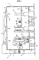
- Fig. 1 is a schematic view showing an exemplary pulling room of the present invention.
- Fig. 2 is a perspective view showing an exemplary pulling room of the present invention.
- Fig. 3 is a schematic view showing a conventional pulling room.
- the inventors of the present invention found that, if, in a cleaned pulling room installed with a plurality of crystal pulling apparatuses and having a plurality of operation floors, wherein clean air is supplied as a down flow from a ceiling or at an upper position near the ceiling, operations performed on the floors could be separated depending on degree of cleanness required for each operation, high degree of cleanness could be maintained in the room and the pulling apparatuses, thus generation of crystal growth failure or quality degradation of crystal due to contamination with dusting substances can be prevented and operations at a high position using a ladder or the like required in connection with use of a larger pulling apparatus can be eliminated. They further defined various conditions therefor and thus accomplished the present invention.
- the pulling room of the present invention is a pulling room installed with a plurality of crystal pulling apparatuses, having a plurality of operation floors, and supplied with clean air as a down flow from a ceiling or at an upper position near the ceiling, and it is constituted by providing three or more of operation floors according to degree of cleanness required for operations performed on each of the operation floors.
- the floor structure may be specifically constituted by an operation floor for loading of raw material and unloading of single crystal ingots that require high degree of cleanness, which is provided in an uppermost story, an operation floor of low degree of cleanness for cleaning of inside of pulling apparatuses accompanied by dusting after production of single crystals and assembling of furnace body constituting members, which is provided in an intermediate story, and an operation floor on which pulling apparatus bodies, incidental facilities thereof and utility facilities not requiring cleanness so much are installed and maintenance operations therefor are performed, which is provided in a lowermost story.
- Fig. 1 is a schematic view showing an example of the pulling room of the present invention.
- Fig. 2 is a perspective view of the same.
- the pulling room shown in Fig. 1 is a pulling room provided with three-story operation floor, in which several to several tens of single crystal pulling apparatuses 11 are installed in the pulling room 1, and it is divided into three stories, an upper story, middle story and lower story, by an uppermost floor 30 and an intermediate floor 31.
- a circulation type air conditioning system 2 in which clean air is blown off from a blow-off outlet 10 of filter 8 disposed near the ceiling of the upper story and contaminated flow is evacuated from a return duct 4 disposed on a side wall of the lower story or the like through the ventilation holes 6 provided on the uppermost floor 30 and the intermediate floor 31, thermally controlled by a heat exchanger 9, and sent out to a ventilation duct 3 by a ventilation fan 7.
- the lowermost floor 32 there are provided, besides the bodies of the pulling apparatuses 11, accessory apparatuses for operating the pulling apparatuses (electric power units, vacuum pumps, control panels, oil pressure apparatuses etc.), utility facilities 12 including piping for circulating cooling water, piping for waste gas, power cables and so forth. Extraordinarily clean environment is not required for this floor.
- the uppermost floor 30 is separated from the intermediate floor 31 for performing the cleaning operation and so forth, it is always maintained at high degree of cleanness and is suitable for loading the raw material and so forth. In particular, even if the charging of the raw material, dismantlement and cleaning are simultaneously performed in each of a plurality of pulling apparatuses 11, these operations are performed on the separate floors and therefore they do not influence on one another at all.
- the raw material 23 and a dopant can be supplied into the quartz crucible 24, then a lid can be placed on it, inside of the crucible can be made vacuum, and the crucible can be hanged by a crane and set into the pulling apparatus by, for example, the method described in Japanese Patent Publication (Kokoku) No. 6-102587.
- the crane for hanging the quartz crucible 24 its arm is attached to the pulling apparatus body (not shown in the drawings), and it utilizes a method of reeling up a wire by a motor via the arm.
- the upper part of the furnace body can be opened by lifting and turning the pull chamber 22 by means of a turning mechanism 33 so that the crucible and the raw material can be hung from above and set in the furnace.
- the main chamber 21 can also be lifted and revolved by a turning mechanism not shown in the drawings.
- the lowermost floor 32 there are provided, besides the bodies of the pulling apparatuses 11, accessory apparatuses for operating the pulling apparatuses (electric power units, vacuum pumps, control panels, oil pressure apparatuses etc.), utility facilities 12 including piping for circulating cooling water, piping for waste gas, power cables and so forth, and everyday check of short circuit, leakage of water etc., maintenance, cleaning and so forth are performed.
- accessory apparatuses for operating the pulling apparatuses electric power units, vacuum pumps, control panels, oil pressure apparatuses etc.
- utility facilities 12 including piping for circulating cooling water, piping for waste gas, power cables and so forth, and everyday check of short circuit, leakage of water etc., maintenance, cleaning and so forth are performed.
- these instruments and facilities do not require extraordinarily clean environment, sufficient operation effect can be obtained even with the degree of cleanness of the down flow that has passed through the intermediate floor 31.
- the present invention was explained by exemplifying a pulling room provided with three floors.
- the present invention is not limited to it, and four floors or five or more floors can also be provided in order to more finely subdividing the degree of cleanness depending on the purpose.
- the required crystal diameter will become larger, the heights of the pulling apparatus and pulling room will become higher and thus the need of four or more floors will become higher in future.
- the degree of cleanness was explained to be set at class 1,000 on the uppermost story, it can of course be set at class 100 or class 10, for example.
- the pulling apparatus used in the present invention may be not only a room for performing the usual Czochralski method, but also one for performing the MCZ method (Magnetic field applied Czochralski method), in which a magnetic field is applied at the time of pulling of a silicon single crystal.
- MCZ method Magnetic field applied Czochralski method
Landscapes
- Engineering & Computer Science (AREA)
- Chemical & Material Sciences (AREA)
- Combustion & Propulsion (AREA)
- Mechanical Engineering (AREA)
- General Engineering & Computer Science (AREA)
- Crystals, And After-Treatments Of Crystals (AREA)
- Ventilation (AREA)
Abstract
A cleaned pulling room installed with a
plurality of single crystal pulling apparatuses,
having a plurality of operation floors and supplied
with clean air as a down flow from a ceiling or an
upper position neighboring the ceiling, wherein at
least three operation floors are provided depending
on degrees of cleanness required for operations
performed on each of the floors. Thus, there is
provided a pulling room that can separate dusting
operations such as operations of dismantlement and
cleaning of the furnace body and structural members
in the furnace body and operations requiring highly
clean environment such as charging of raw material
into the furnace body as preparation for starting
running of the pulling apparatuses, and can secure
safety of the operations even when the pulling
apparatuses become larger.
Description
The present invention relates to a floor
structure of a pulling room in which single crystal
pulling apparatuses are installed.
Conventionally, several to several tens of
pulling apparatuses for semiconductor single
crystals such as those of silicon used as
semiconductor substrate materials are installed in
one pulling room, and the pulling room in which the
apparatuses are installed is divided into two
stories including an upper story which requires high
cleanness and a lower story in which the pulling
apparatus bodies, utility facilities for running the
apparatuses and so forth are installed, and has a
structure where clean air is always supplied and
flown downwardly from a ceiling of the pulling room
or a position in the vicinity of it.
For example, the pulling room shown in Fig. 3
is one having two-story operation floor. In the
pulling room 1, several to several tens of pulling
apparatuses 11 for pulling single crystals (those
based on the Czochralski method) are installed, and
it is divided into two stories of the upper story
and the lower story by an upper operation floor 13
having ventilation holes 6. Further, there is
provided a circulation type air conditioning system
2, in which clean air is blown off from a blow-off
outlets 10 of filters 8 disposed near the ceiling of
the upper story and contaminated flow is evacuated
from a return duct 4 disposed on a side wall of the
lower story or the like through the ventilation
holes 6, thermally controlled by a heat exchanger 9,
and sent out to a ventilation duct 3 by a
ventilation fan 7.
Furthermore, on the lower operation floor 14,
there are provided, besides the bodies of the
pulling apparatuses 11, accessory apparatuses for
operating the pulling apparatuses (electric power
units, vacuum pumps, control panels, oil pressure
apparatuses etc.), utility facilities 12 including
piping for circulating cooling water, piping for
waste gas, power cables and so forth. Although
extraordinarily clean environment is not required
for this pulling room, certain means are required in
order to maintain the clean environment of the upper
story.
In the pulling room 1, various operations are
commonly conducted on the upper operation floor 13,
which include taking out of a single crystal ingot
20 after the production through a door 27 for taking
out a single crystal ingot of the pulling apparatus
11 by using a step 28, unloading operation for
subsequent steps, dismantlement and cleaning of a
furnace body and structural members in the furnace
body, such as a main chamber 21, pulling chamber 22,
graphite crucible 25, graphite heater and heat
insulating material, loading of raw material and so
forth, which are performed for subsequent production
of single crystals. On the upper operation floor 13,
in particular, it is indispensable to supply clean
air to maintain high degree of cleanness, because
there are used raw material polycrystal silicon 23,
quartz crucible 24 and so forth, which hate dusts.
In order to improve the internal environment of
such a pulling room, various attempts have been made
as described below.
First, in order to prevent influence of dusting
upon dismantlement and cleaning of pulling apparatus
on an adjacent pulling apparatus, the applicant of
the present application proposed a system in which a
blowing off nozzle for clean air is provided at a
position above a pulling apparatus and a suction fan
is provided in or below a base disposed below the
pulling apparatus body to prevent diffusion of down
flow (refer to Japanese Patent Laid-open (Kokai)
Publication No. 6-159751).
Further, the applicant of the present
application also proposed a pulling apparatus
provided with a local operation deck, local ladder
or the like in order to improve workability and
secure safety, because conventional two-story floor
structure became unable to meet requirements arisen
in connection with use of a larger pulling apparatus
used for single crystals of a larger diameter (refer
to Japanese Patent Application No. 11-113335).
Furthermore, there was proposed a system in
which pulling apparatuses are disposed one by one in
compartmentalized rooms in order to prevent the
influence of dusting on surroundings, and clean air
is supplied from an upper story to a lower story so
that desired degree of cleanness should be obtained
for each story floor provided therein (refer to US
Patent No. 5,641,354). Although a three-story floor
structure was disclosed in this invention, the
pulling apparatuses are disposed one by one in
compartmentalized rooms and the floor is
compartmentalized, and therefore filters, ducts and
so forth for air conditioning are required for each
room. Accordingly, the installation area per
pulling apparatus becomes larger and the
construction cost increases. Further, an automatic
transportation apparatus is required as a measure
for use of heavier weight, but introduction of such
an automatic transportation apparatus into such a
room is troublesome. Moreover, it also suffers from
other problems, for example, when a pulling
apparatus must be replaced, the limitation
concerning layout imposed by the compartmentalized
cell structure makes it impossible to replace it
with a larger apparatus. In addition, it also
suffers from disadvantages, for example, when on-site
monitoring is performed, the monitoring must be
performed for every rooms because of the
compartmentalized structure, and thus it is
impossible to quickly perform maintenance operations
or cope with an emergent situation such as at the
time of electric power failure.
Semiconductor devices have rapidly become finer
and hence higher quality of single crystals has come
to be required, and this technical tide tends to be
further accelerated in connection with use of a
larger diameter of the crystals. Under such a
situation, if dusting operations such as
dismantlement and cleaning of the furnace body and
structural members in the furnace body and operation
requiring highly clean environment such as charging
of raw material into the furnace body as preparation
for starting running of the pulling apparatus are
performed on the same operation floor as
conventional techniques, dusting substances may
contaminate the charged raw materials and may cause
degradation of single crystal ingot quality or
adversely affect the workability. In particular, in
a pulling room in which a plurality of pulling
apparatuses are installed, the cleaning operation
and raw material charging operation of adjacent
pulling apparatuses may be simultaneously performed
on the same operation floor, and the problems become
more serious.
Further, in order to solve the aforementioned
problems, it has been also aimed at to reduce
construction cost and maintenance cost by using a
smaller installation area per pulling apparatus and
using minimum facilities including filters and ducts
for air conditioning. Moreover, there are also
desired ameliorations of the limitations concerning
layout in cases of introducing an automatic
transportation apparatus as a measure for use of
heavy weight or replacement of pulling apparatus, in
particular, in a case of replacement with a larger
pulling apparatus, easier on-site monitoring, and
quicker maintenance and quicker emergent operation
such as at the time of electric power failure.
Furthermore, use of a larger pulling apparatus
has advanced in such a degree that height of
apparatus should exceed 10 m, and difference between
the height for the operation of taking out a single
crystal after the production and the height for the
operation of dismantlement and cleaning of the
furnace body and structural members in the furnace
body tends to become larger, and methods for
securing degree of cleanness of operation
environment correspond to each operation and
securing safety have been studied.
Therefore, the present invention has been
accomplished in view of such conventional problems,
and its main object is to provide a pulling room in
which a plurality of pulling apparatuses are
installed, which can separate dusting operations
such as operations of dismantlement and cleaning of
the furnace body and structural members in the
furnace body and operations requiring highly clean
environment such as charging of raw material into
the furnace body as preparation for starting running
of the pulling apparatuses, and can secure safety of
the operations even when the pulling apparatuses
become larger.
In order to achieve the aforementioned object,
the pulling room of the present invention is a
cleaned pulling room installed with a plurality of
single crystal pulling apparatuses, having a
plurality of operation floors and supplied with
clean air as a down flow from a ceiling or an upper
position neighboring the ceiling, wherein at least
three operation floors are provided depending on
degrees of cleanness required for operations
performed on each of the floors.
In such a pulling room, clean air is supplied
as a down flow from the ceiling with degree of
cleanness according to degree of cleanness required
at each of, for example, at least three operation
floors of the pulling room including an uppermost
floor, intermediate floor and lowermost floor. Thus,
an operation requiring the highest degree of
cleanness can be performed on the uppermost floor,
an operation for which slightly lower degree of
cleanness is sufficient can be performed on the
intermediate floor, and an operation that does not
require degree of cleanness so much can be performed
on the lowermost floor. Therefore, single crystal
pulling operations requiring different degrees of
cleanness depending on types of the operations can
be separately performed on each of the floors.
By using such a configuration as described
above, the installation area per pulling apparatus
can be made smaller, and maintenance becomes easier
since facilities such as filters and ducts for air
conditioning can be simplified. Therefore, the
construction cost and the maintenance cost for
facilities can be reduced. In particular, when an
automatic transportation apparatus is introduced as
a measure for use of heavier weight, there is
required a passage where the automatic
transportation apparatus is passed. However, since
the room is not compartmentalized as rooms on each
floor, it can be introduced extremely easily.
Furthermore, there are also obtained advantages that,
when on-site monitoring is performed, it can be
performed easily also because the room is not
compartmentalized as rooms, and an emergent
situation such as at the time of electric power
failure can be coped with quickly. Moreover, since
the room is not compartmentalized as rooms, it
suffers from less limitation concerning layout, and
pulling apparatuses can be easily replaced. In
particular, if the height of the ceiling is designed
to be sufficiently high for introduction of a large
pulling apparatus, so much difficulty is not caused.
In the present invention, the floor structure
of the pulling room may comprise at least an
operation floor for loading of raw material and
unloading of single crystals that require high
degree of cleanness, which is provided in an
uppermost story, an operation floor of low degree of
cleanness for cleaning of inside of pulling
apparatuses accompanied by dusting after production
of single crystals and assembling of furnace body
structural members, which is provided in an
intermediate story, and an operation floor on which
pulling apparatus bodies, incidental facilities
thereof and utility facilities not requiring
cleanness are installed and maintenance operations
therefor are performed, which is provided in a
lowermost story.
At least three floors can be used as the floors
of the pulling room as described above, in which the
uppermost floor can be used as an operation floor on
which loading of raw materials such as polycrystal
and quartz crucible and unloading of single crystal
ingots after the production that require the highest
degree of cleanness are performed, the intermediated
floor can be used as an operation floor on which
cleaning of inside of pulling apparatuses
accompanied by dusting and assembling of furnace
body constituting internal members (graphite
members) for subsequent operation, which requires a
certain degree of cleanness, are performed, and the
lowermost floor can be used as an operation floor
not requiring particular cleanness on which pulling
apparatus bodies, incidental facilities thereof and
utility facilities are installed and maintenance
operations therefor are performed. By using the
above structure, even when a plurality of pulling
apparatuses are installed, the raw material charging
operation and the dusting operations can always be
separated, and thus generation of crystal growth
failure or quality degradation of crystal due to
contamination of the raw material and so forth with
dusts can be prevented. Further, since the
unloading operation of grown single crystal ingots
can be performed on the uppermost floor, it becomes
unnecessary to carry out operations at a high
position by using a ladder or the like, and thus
safety can be secured.
According to the present invention, even in a
pulling room installed with a plurality of pulling
apparatuses, clean air blown off from the ceiling
direction as a down flow is not contaminated with
dusting substances in the room, thus it becomes
possible to perform operations on each of the
stratified floors with a desired degree of cleanness
and thereby generation of crystal growth failure or
quality degradation of crystal due to contamination
with dusting substances can be prevented. In
particular, this structure can cancel the
contradiction of the conventional technique that the
loading of raw material and the cleaning operation
of inside of the furnace body are performed on a
floor of the same degree of cleanness.
Further, while the difference between the
height for the operation of taking out a single
crystal ingot after the production and the height
for the operation of cleaning of inside of the
furnace body has become larger due to use of a
larger pulling apparatus, operations at a high
position using a step or the like are made
unnecessary by the use of three or more floors, and
thus there is also obtained an advantage that safety
is secured.
Fig. 1 is a schematic view showing an exemplary
pulling room of the present invention.
Fig. 2 is a perspective view showing an
exemplary pulling room of the present invention.
Fig. 3 is a schematic view showing a
conventional pulling room.
Embodiments of the present invention will be
explained hereafter. However, the present invention
is not limited to these.
The inventors of the present invention found
that, if, in a cleaned pulling room installed with a
plurality of crystal pulling apparatuses and having
a plurality of operation floors, wherein clean air
is supplied as a down flow from a ceiling or at an
upper position near the ceiling, operations
performed on the floors could be separated depending
on degree of cleanness required for each operation,
high degree of cleanness could be maintained in the
room and the pulling apparatuses, thus generation of
crystal growth failure or quality degradation of
crystal due to contamination with dusting substances
can be prevented and operations at a high position
using a ladder or the like required in connection
with use of a larger pulling apparatus can be
eliminated. They further defined various conditions
therefor and thus accomplished the present invention.
As described above, the pulling room of the
present invention is a pulling room installed with a
plurality of crystal pulling apparatuses, having a
plurality of operation floors, and supplied with
clean air as a down flow from a ceiling or at an
upper position near the ceiling, and it is
constituted by providing three or more of operation
floors according to degree of cleanness required for
operations performed on each of the operation floors.
Further, the floor structure may be
specifically constituted by an operation floor for
loading of raw material and unloading of single
crystal ingots that require high degree of cleanness,
which is provided in an uppermost story, an
operation floor of low degree of cleanness for
cleaning of inside of pulling apparatuses
accompanied by dusting after production of single
crystals and assembling of furnace body constituting
members, which is provided in an intermediate story,
and an operation floor on which pulling apparatus
bodies, incidental facilities thereof and utility
facilities not requiring cleanness so much are
installed and maintenance operations therefor are
performed, which is provided in a lowermost story.
Hereafter, the functions of the pulling room of
the present invention will be explained by referring
the appended drawings.
Fig. 1 is a schematic view showing an example
of the pulling room of the present invention. Fig.
2 is a perspective view of the same.
For example, the pulling room shown in Fig. 1
is a pulling room provided with three-story
operation floor, in which several to several tens of
single crystal pulling apparatuses 11 are installed
in the pulling room 1, and it is divided into three
stories, an upper story, middle story and lower
story, by an uppermost floor 30 and an intermediate
floor 31. Further, there is provided a circulation
type air conditioning system 2, in which clean air
is blown off from a blow-off outlet 10 of filter 8
disposed near the ceiling of the upper story and
contaminated flow is evacuated from a return duct 4
disposed on a side wall of the lower story or the
like through the ventilation holes 6 provided on the
uppermost floor 30 and the intermediate floor 31,
thermally controlled by a heat exchanger 9, and sent
out to a ventilation duct 3 by a ventilation fan 7.
Furthermore, on the lowermost floor 32, there
are provided, besides the bodies of the pulling
apparatuses 11, accessory apparatuses for operating
the pulling apparatuses (electric power units,
vacuum pumps, control panels, oil pressure
apparatuses etc.), utility facilities 12 including
piping for circulating cooling water, piping for
waste gas, power cables and so forth.
Extraordinarily clean environment is not required
for this floor.
Hereafter, various operations performed for
production for single crystals in the pulling room 1
will be explained.
First, on the uppermost floor 30 which requires
the highest degree of cleanness, taking out of a
completed single crystal ingot 20 through a door 27
for taking out a single crystal ingot of a pulling
chamber 22 of the pulling apparatus 11 and unloading
operation for subsequent steps are performed. Thus,
the taking out and the unloading operation of a
single crystal ingot, which is recently getting
heavier weight, can be performed on the uppermost
floor 30, and therefore these operations can be
easily performed without a step or the like as in a
conventional operation. Accordingly, these
operations are not operations at a high position,
and hence safety is also secured.
Further, on the uppermost floor, loading of the
raw material polycrystal silicon 23, quartz crucible
24 and so forth, which hate dusts, is performed for
the subsequent production of a single crystal.
Since the uppermost floor 30 is separated from
the intermediate floor 31 for performing the
cleaning operation and so forth, it is always
maintained at high degree of cleanness and is
suitable for loading the raw material and so forth.
In particular, even if the charging of the raw
material, dismantlement and cleaning are
simultaneously performed in each of a plurality of
pulling apparatuses 11, these operations are
performed on the separate floors and therefore they
do not influence on one another at all.
In addition, in order to set the raw material
located on the uppermost floor 30 into the pulling
apparatus 11, the raw material 23 and a dopant can
be supplied into the quartz crucible 24, then a lid
can be placed on it, inside of the crucible can be
made vacuum, and the crucible can be hanged by a
crane and set into the pulling apparatus by, for
example, the method described in Japanese Patent
Publication (Kokoku) No. 6-102587.
As for the crane for hanging the quartz
crucible 24, its arm is attached to the pulling
apparatus body (not shown in the drawings), and it
utilizes a method of reeling up a wire by a motor
via the arm. Further, in order to set the quartz
crucible 24 in the pulling apparatus, the upper part
of the furnace body can be opened by lifting and
turning the pull chamber 22 by means of a turning
mechanism 33 so that the crucible and the raw
material can be hung from above and set in the
furnace. In addition, when the furnace is
dismantled and cleaned, the main chamber 21 can also
be lifted and revolved by a turning mechanism not
shown in the drawings.
On the intermediate floor 31, dismantlement,
cleaning and assembling of the furnace body and
structural members in the furnace body of the
pulling apparatus and so forth are performed. These
operations are accompanied by quite dusting.
However, since ventilation holes 6 are provided also
on the intermediate floor 31 and a down flow of
clean air is secured in the pulling room, it does
not affect on the upper story. Thus, the
transportation and charging operations for the raw
material and the crucible, which require high degree
of cleanness, and the operations of dismantlement
and cleaning of the pulling apparatus accompanied by
dusting can be completely separated from each other.
In this case, it is more preferred that clean air
can be supplied as a down flow from a position right
above the place where the dismantlement operation is
performed so that dusts should not remain so much in
the pulling apparatus after the dismantlement and
cleaning operation.
On the lowermost floor 32, there are provided,
besides the bodies of the pulling apparatuses 11,
accessory apparatuses for operating the pulling
apparatuses (electric power units, vacuum pumps,
control panels, oil pressure apparatuses etc.),
utility facilities 12 including piping for
circulating cooling water, piping for waste gas,
power cables and so forth, and everyday check of
short circuit, leakage of water etc., maintenance,
cleaning and so forth are performed. However, since
these instruments and facilities do not require
extraordinarily clean environment, sufficient
operation effect can be obtained even with the
degree of cleanness of the down flow that has passed
through the intermediate floor 31.
If operation floors maintaining degrees of
cleanness suitable for each operation are provided
as described above, although the degree of cleanness
of the uppermost floor, on which the raw material is
loaded, set at, for example, class 1,000, is
degraded to about class 10,000 when the
dismantlement and cleaning operations of inside of
the furnace body is performed, it does not affect
the uppermost floor at all. Thus, high degree of
cleanness is maintained, and it becomes possible to
safely perform the operations requiring high degree
of cleanness such as loading of the raw material
without any problem.
The present invention is not limited to the
embodiments described above. The above-described
embodiments are mere examples, and any of those
having the substantially same configuration as that
described in the appended claims and providing
similar functions and advantages are included in the
scope of the present invention.
For example, in the embodiments described above,
the present invention was explained by exemplifying
a pulling room provided with three floors. However,
the present invention is not limited to it, and four
floors or five or more floors can also be provided
in order to more finely subdividing the degree of
cleanness depending on the purpose. In particular,
the required crystal diameter will become larger,
the heights of the pulling apparatus and pulling
room will become higher and thus the need of four or
more floors will become higher in future. Although
the degree of cleanness was explained to be set at
class 1,000 on the uppermost story, it can of course
be set at class 100 or class 10, for example.
Further, the pulling apparatus used in the
present invention may be not only a room for
performing the usual Czochralski method, but also
one for performing the MCZ method (Magnetic field
applied Czochralski method), in which a magnetic
field is applied at the time of pulling of a silicon
single crystal.
Claims (2)
- A cleaned pulling room installed with a plurality of single crystal pulling apparatuses, having a plurality of operation floors and supplied with clean air as a down flow from a ceiling or an upper position neighboring the ceiling, wherein at least three operation floors are provided depending on degrees of cleanness required for operations performed on each of the floors.
- The pulling room according to Claim 1, wherein floor structure of the pulling room comprises at least an operation floor for loading of raw material and unloading of single crystals that require high degree of cleanness, which is provided in an uppermost story, an operation floor of low degree of cleanness for cleaning of inside of pulling apparatuses accompanied by dusting after production of single crystals and assembling of furnace body constituting members, which is provided in an intermediate story, and an operation floor on which pulling apparatus bodies, incidental facilities thereof and utility facilities not requiring cleanness are installed and maintenance operations therefor are performed, which is provided in a lowermost story.
Applications Claiming Priority (3)
| Application Number | Priority Date | Filing Date | Title |
|---|---|---|---|
| JP2000333507 | 2000-10-31 | ||
| JP2000333507A JP2002138620A (en) | 2000-10-31 | 2000-10-31 | Pulling room |
| PCT/JP2001/009436 WO2002037034A1 (en) | 2000-10-31 | 2001-10-26 | Pulling room |
Publications (2)
| Publication Number | Publication Date |
|---|---|
| EP1331454A1 true EP1331454A1 (en) | 2003-07-30 |
| EP1331454A4 EP1331454A4 (en) | 2006-05-17 |
Family
ID=18809581
Family Applications (1)
| Application Number | Title | Priority Date | Filing Date |
|---|---|---|---|
| EP01976843A Withdrawn EP1331454A4 (en) | 2000-10-31 | 2001-10-26 | DRAWING ROOM |
Country Status (6)
| Country | Link |
|---|---|
| US (1) | US20030000457A1 (en) |
| EP (1) | EP1331454A4 (en) |
| JP (1) | JP2002138620A (en) |
| KR (1) | KR100809727B1 (en) |
| TW (1) | TW540094B (en) |
| WO (1) | WO2002037034A1 (en) |
Cited By (1)
| Publication number | Priority date | Publication date | Assignee | Title |
|---|---|---|---|---|
| CN108756317A (en) * | 2018-06-20 | 2018-11-06 | 长兴云腾新能源科技有限公司 | A kind of semiconductor dust free room |
Families Citing this family (7)
| Publication number | Priority date | Publication date | Assignee | Title |
|---|---|---|---|---|
| WO2005073439A1 (en) * | 2004-02-02 | 2005-08-11 | Shin-Etsu Handotai Co., Ltd. | Silicon single crystal, silicon wafer, production apparatus therefor and process for producing the same |
| JP2008266058A (en) * | 2007-04-18 | 2008-11-06 | Shin Etsu Handotai Co Ltd | Pulling room |
| US7974689B2 (en) * | 2007-06-13 | 2011-07-05 | Zoll Medical Corporation | Wearable medical treatment device with motion/position detection |
| JP4984175B2 (en) * | 2008-12-05 | 2012-07-25 | 株式会社ダイフク | Single crystal rod growth equipment |
| JP4984176B2 (en) * | 2008-12-09 | 2012-07-25 | 株式会社ダイフク | Single crystal rod growth equipment |
| JP6911799B2 (en) * | 2018-03-15 | 2021-07-28 | 信越半導体株式会社 | Clean booth for silicon polycrystalline filling work |
| JP7820251B2 (en) * | 2022-06-30 | 2026-02-25 | 日揮株式会社 | working structure |
Family Cites Families (14)
| Publication number | Priority date | Publication date | Assignee | Title |
|---|---|---|---|---|
| JPS6196344A (en) * | 1984-10-18 | 1986-05-15 | Toshiba Corp | Clean room |
| JPS625031A (en) * | 1985-06-28 | 1987-01-12 | Kajima Corp | Clean room with different levels of cleanliness |
| JPH0756879B2 (en) * | 1988-03-31 | 1995-06-14 | 日鉄セミコンダクター株式会社 | Semiconductor dust-free manufacturing equipment |
| JPH04310592A (en) * | 1991-04-03 | 1992-11-02 | Shin Etsu Handotai Co Ltd | Automatic production system for single crystal |
| JPH05205988A (en) * | 1992-01-24 | 1993-08-13 | Fujitsu Ltd | Manufacturing device for dust-free room |
| JP2780235B2 (en) * | 1992-11-20 | 1998-07-30 | 信越半導体株式会社 | Clean room system |
| US5641354A (en) * | 1995-07-10 | 1997-06-24 | Seh America, Inc. | Puller cell |
| JPH09221381A (en) * | 1996-02-08 | 1997-08-26 | Komatsu Electron Metals Co Ltd | Evacuating device for device for pulling up single crystal |
| JP3254373B2 (en) * | 1996-03-25 | 2002-02-04 | 松下電器産業株式会社 | Clean room and its operation method |
| JPH1070055A (en) * | 1996-08-28 | 1998-03-10 | Sony Corp | Clean room for semiconductor device production |
| JPH10310491A (en) * | 1997-05-02 | 1998-11-24 | Sumitomo Sitix Corp | Single crystal take-out apparatus and method |
| JPH1191937A (en) * | 1997-09-22 | 1999-04-06 | Ohbayashi Corp | Transporting method for ingot |
| JP3594172B2 (en) * | 1998-05-19 | 2004-11-24 | 東芝セラミックス株式会社 | Mounting device and replacement device for crucible assembly or hot zone member, and drive control method for crucible assembly replacement device |
| JP2002048370A (en) * | 2000-07-31 | 2002-02-15 | Shin Etsu Handotai Co Ltd | Lifting chamber |
-
2000
- 2000-10-31 JP JP2000333507A patent/JP2002138620A/en active Pending
-
2001
- 2001-10-26 WO PCT/JP2001/009436 patent/WO2002037034A1/en not_active Ceased
- 2001-10-26 EP EP01976843A patent/EP1331454A4/en not_active Withdrawn
- 2001-10-26 US US10/181,651 patent/US20030000457A1/en not_active Abandoned
- 2001-10-26 KR KR1020027007725A patent/KR100809727B1/en not_active Expired - Fee Related
- 2001-10-30 TW TW090126836A patent/TW540094B/en not_active IP Right Cessation
Cited By (1)
| Publication number | Priority date | Publication date | Assignee | Title |
|---|---|---|---|---|
| CN108756317A (en) * | 2018-06-20 | 2018-11-06 | 长兴云腾新能源科技有限公司 | A kind of semiconductor dust free room |
Also Published As
| Publication number | Publication date |
|---|---|
| KR100809727B1 (en) | 2008-03-07 |
| TW540094B (en) | 2003-07-01 |
| JP2002138620A (en) | 2002-05-17 |
| US20030000457A1 (en) | 2003-01-02 |
| KR20020070325A (en) | 2002-09-05 |
| EP1331454A4 (en) | 2006-05-17 |
| WO2002037034A1 (en) | 2002-05-10 |
Similar Documents
| Publication | Publication Date | Title |
|---|---|---|
| US5749967A (en) | Puller cell | |
| JP2620037B2 (en) | Production plant for producing semiconductor integrated circuit device and method of constructing the plant | |
| US7828928B2 (en) | Vacuum processing apparatus | |
| US4838150A (en) | Clean room | |
| JPH08510826A (en) | Environmental control system | |
| US20030000457A1 (en) | Pulling room | |
| CN1106887A (en) | Integrated building and conveying structure for manufacturing under ultraclean conditions | |
| US11133208B2 (en) | EFEM and method of introducing dry air thereinto | |
| US5380684A (en) | Method for transferring wafers from one processing station to another sequentially and system therefor | |
| US5972060A (en) | Apparatus for providing a purified resource in a manufacturing facility | |
| KR20230163967A (en) | Apparatus for reducing moisture of front opening unified pod in load port module and semiconductor process device comprising the same | |
| KR102517416B1 (en) | Hybrid air cleaning system of ventilation system | |
| US20090205564A1 (en) | Crystal-growing furnace system | |
| KR102611746B1 (en) | Clean booth for silicon polycrystalline filling work | |
| KR20240117515A (en) | Efem with humidity control function | |
| KR20240094953A (en) | Humidity control efem | |
| JP3254373B2 (en) | Clean room and its operation method | |
| JP2695931B2 (en) | Elevator equipment for clean room | |
| JP2001181086A (en) | Method for growing single crystal by fz method | |
| CA2624706A1 (en) | Method of operating a plurality of clean room | |
| JP2003240290A (en) | Air conditioning system for multi-layer clean room | |
| JPH10238833A (en) | Clean room | |
| JPH11211215A (en) | Ceiling-hung type air conditioner | |
| JP2004108630A (en) | Clean room | |
| JP2695932B2 (en) | Elevator equipment for clean room |
Legal Events
| Date | Code | Title | Description |
|---|---|---|---|
| PUAI | Public reference made under article 153(3) epc to a published international application that has entered the european phase |
Free format text: ORIGINAL CODE: 0009012 |
|
| 17P | Request for examination filed |
Effective date: 20020805 |
|
| AK | Designated contracting states |
Designated state(s): AT BE CH CY DE DK ES FI FR GB GR IE IT LI LU MC NL PT SE TR |
|
| RBV | Designated contracting states (corrected) |
Designated state(s): DE |
|
| A4 | Supplementary search report drawn up and despatched |
Effective date: 20060330 |
|
| 17Q | First examination report despatched |
Effective date: 20061222 |
|
| RAP1 | Party data changed (applicant data changed or rights of an application transferred) |
Owner name: SHIN-ETSU HANDOTAI CO., LTD. |
|
| STAA | Information on the status of an ep patent application or granted ep patent |
Free format text: STATUS: THE APPLICATION IS DEEMED TO BE WITHDRAWN |
|
| 18D | Application deemed to be withdrawn |
Effective date: 20100920 |