EP1331336A2 - Halterung für einen Scharnierzapfen eines Fenster-, Tür- oder Möbelscharniers - Google Patents
Halterung für einen Scharnierzapfen eines Fenster-, Tür- oder Möbelscharniers Download PDFInfo
- Publication number
- EP1331336A2 EP1331336A2 EP03001148A EP03001148A EP1331336A2 EP 1331336 A2 EP1331336 A2 EP 1331336A2 EP 03001148 A EP03001148 A EP 03001148A EP 03001148 A EP03001148 A EP 03001148A EP 1331336 A2 EP1331336 A2 EP 1331336A2
- Authority
- EP
- European Patent Office
- Prior art keywords
- holder according
- hinge pin
- adjustment
- hinge
- pin
- Prior art date
- Legal status (The legal status is an assumption and is not a legal conclusion. Google has not performed a legal analysis and makes no representation as to the accuracy of the status listed.)
- Withdrawn
Links
- 238000004519 manufacturing process Methods 0.000 claims description 6
- 230000001154 acute effect Effects 0.000 claims description 4
- 239000012858 resilient material Substances 0.000 claims description 3
- 238000010276 construction Methods 0.000 description 12
- 230000000694 effects Effects 0.000 description 3
- 238000003754 machining Methods 0.000 description 2
- 230000009286 beneficial effect Effects 0.000 description 1
- 230000005540 biological transmission Effects 0.000 description 1
- 238000006073 displacement reaction Methods 0.000 description 1
- 238000003780 insertion Methods 0.000 description 1
- 230000037431 insertion Effects 0.000 description 1
- 239000000463 material Substances 0.000 description 1
Images

Classifications
-
- E—FIXED CONSTRUCTIONS
- E05—LOCKS; KEYS; WINDOW OR DOOR FITTINGS; SAFES
- E05D—HINGES OR SUSPENSION DEVICES FOR DOORS, WINDOWS OR WINGS
- E05D7/00—Hinges or pivots of special construction
- E05D7/04—Hinges adjustable relative to the wing or the frame
- E05D7/0415—Hinges adjustable relative to the wing or the frame with adjusting drive means
- E05D7/0423—Screw-and-nut mechanisms
-
- E—FIXED CONSTRUCTIONS
- E05—LOCKS; KEYS; WINDOW OR DOOR FITTINGS; SAFES
- E05D—HINGES OR SUSPENSION DEVICES FOR DOORS, WINDOWS OR WINGS
- E05D7/00—Hinges or pivots of special construction
- E05D7/04—Hinges adjustable relative to the wing or the frame
- E05D7/043—Hinges adjustable relative to the wing or the frame by means of dowel attachments
-
- E—FIXED CONSTRUCTIONS
- E05—LOCKS; KEYS; WINDOW OR DOOR FITTINGS; SAFES
- E05Y—INDEXING SCHEME ASSOCIATED WITH SUBCLASSES E05D AND E05F, RELATING TO CONSTRUCTION ELEMENTS, ELECTRIC CONTROL, POWER SUPPLY, POWER SIGNAL OR TRANSMISSION, USER INTERFACES, MOUNTING OR COUPLING, DETAILS, ACCESSORIES, AUXILIARY OPERATIONS NOT OTHERWISE PROVIDED FOR, APPLICATION THEREOF
- E05Y2900/00—Application of doors, windows, wings or fittings thereof
- E05Y2900/20—Application of doors, windows, wings or fittings thereof for furniture, e.g. cabinets
Definitions
- the invention relates to a holder for a hinge pin of a window, door or Furniture hinge, in which at least one hinge pin at least in its Operational position positively and / or non-positively with an adjustment part in operative connection can be brought, the adjustment part on its inside, facing away from the hinge axis End area at least one compared to the immediately following Section projecting collar, web, pin or the like. has, being at the free end region an associated hinge pin at least one transverse to the longitudinal axis of the same aligned groove, flattening, recess or the like. is formed, and wherein the adjustment part and the associated hinge pin at least in their operating position at their mutually facing areas directly and positively with one another are in operative connection.
- a bracket of the type mentioned is known from DE 197 30 143 C1. Since the Hinge pins and also assembly parts for receiving an adjustment part in the holes a door or a window must be used, a production is required of the bore in very tight tolerances, with the bores generally in one another following steps are made so that compliance with small Tolerance ranges becomes even more difficult.
- the invention has therefore set itself the task of holding the aforementioned Type to create, which in functional terms, the advantages of the known design maintains, but also with deviations in a larger tolerance range in the vertical and angular position of the holes for the holder optimal assembly and functional reliability is still guaranteed.
- the adjustment part consists of a collar, web, Pin or the like.
- a connecting web and one at the other end to the connecting web subsequent cross piece formed with a threaded bore is, wherein an adjusting screw engages in the threaded bore of the cross piece.
- the crosspiece and the connecting web of the adjustment part enclose an obtuse angle with one another, the free end of the connecting web, in the area of which the federal government, web, pin or the like. connects, essentially lies in the area of the axis of the threaded hole in the cross piece. It can Not only can a space-saving construction be achieved, but it is too an optimal variant of the power transmission during adjustment has been created. Furthermore, a secure intervention of the federal government, web, pin or the like is thereby. into the corresponding one Groove, flattening, recess or the like. guaranteed.
- the adjusting screw together with the adjusting part by one through the head of the adjusting screw imaginary transverse axis is rotatable in a small angular range. this will by holding the head of the screws with slight axial play.
- a simple design variant provides that the spring between the adjustment part and the mounting part is a leaf spring.
- the adjustment part or at least the connecting web the same is made of a resilient material. Then you can click on the additional one Arrangement of a spring, in particular a leaf spring, can be dispensed with.
- the trap must also ensure the required stability of the adjustment part. There must not be an automatic adjustment due to tensile or compressive loads come on the hinge pin.
- the adjustment part inserted in a groove open in the radial direction towards one side in the assembly part is whose side walls form a lateral guide for the adjustment part.
- the Adjustment part is optimally held and guided in this way, so that even with relative low material expenditure for the adjustment part sufficient stability for the adjustment and is also guaranteed for the permanently good mounting.
- adjustment part as a bolt with formed on the free engagement area, circumferential collar and with a other end trained threaded portion is executed, one on the threaded portion the attached nut is secured against rotation and with slight axial play securely engages in a groove on the mounting part.
- the adjustment part as a bolt with formed on the free engagement area, circumferential collar and with a other end trained threaded portion is executed, one on the threaded portion the attached nut is secured against rotation and with slight axial play securely engages in a groove on the mounting part.
- the adjustment possibility is also easy handle, namely at the end of a threaded portion of the formed as a bolt an internal attack for attaching a turning tool is provided.
- the resilient training also easy to use. It is proposed that between the a spring designed as a bolt and the mounting part a spring, e.g. a leaf spring, is used.
- the measures according to the invention also enable an optimal mounting multi-part hinges.
- three-part hinges e.g. the hinge pins can be held and adjusted by two hinge parts.
- the invention is therefore provided that the adjustment part in a pocket Housing is used and can be used over a width of more than one Hinge pin extends, with a single adjustment arrangement for this adjustment part is provided with adjusting screw. So you can work with a single adjustment part so that all hinge pins to be inserted and held are gripped can be. It is also a space-saving, optimal fastening for multi-part Hinges have been created.
- the hinge pin and the associated adjustment part and thus also the holes for receiving the hinge pin and the mounting part enclose a tapered, acute angle with each other at their ends.
- the resilient engagement of the adjustment part in the hinge pin bridges relatively large Tolerance ranges.
- a hinge pin in two positions rotated by 180 ° can be held (left or right application), it is suggested that at the the side opposite to the operating position or at least offset at an angle this another groove, flattening, recess or the like. is trained.
- adjustment part is in the assembly part is pre-assembled and the assembly part on the production side in the frame or the window or the door is inserted. This is for both the manufacturer of the doors and windows as well as an optimal variant for the craftsman performing the assembly Service.
- the fixed assembly of the mounting part can of course be done in different ways. With heavy doors in particular, an additional fastening option can be used be beneficial.
- the mounting part as a stop collar Depth stop when inserting into the prepared hole. Especially with arrangement of a stop collar can then also e.g. to be screwed in at an acute angle Screws are provided.
- the adjustment part when pushing it in push back - it is advantageously provided that the hinge pin to its free end towards one or two opposite sides a sloping slope Has flattening or is tapered tapering.
- a hinge pin is held in a door shall be.
- the hinge pins and those according to the invention engage provided bracket on the side boundaries, i.e. in the fold area one Door so that the bracket itself is practically invisible from the outside.
- a stake for doors and of course also for windows is the optimal application.
- the invention Bracket can also be used in other areas in the same way, for example in furniture construction, for door or window frames, but also for door or Window frames in which the solution according to the invention with an additional Mounting part can also be used effectively.
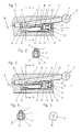
- the adjustment part 3 has on its inside, a web 5 on the end region facing away from the hinge axis 4. Outdoors The end region of the associated hinge pin 1 is one transverse to the longitudinal axis 6 of the same aligned groove 7 formed.
- the adjustment part 3 and the associated hinge pin 1 engage in their use position in holes 8 and 9 on the door 10, wherein the mutually facing end regions of adjusting part 3 and hinge pin 1 form and / or are in a force-locking direct connection with each other. This is achieved by that the web 5 engages in the groove 7 on the free end region of the hinge pin 1, so that with an axial adjustment of the adjustment part 3 also an axial adjustment of the hinge pin 1 is caused.
- the hinge pin 1 of a door hinge 2 is at least one hinge pin 1 form and / or at least in its use position can be positively connected to an adjusting part 3.
- the adjustment part 3 has at its inner end region facing away from the hinge axis 4 at least one above the section immediately following Web 5 on, instead of the web 5 also a corresponding collar, a pin or the like. could be provided.
- At the free end area of the hinge pin to be assigned 1 is at least one groove 7 oriented transversely to the longitudinal axis thereof or a corresponding flattening or recess is formed so that the adjustment part 3 and the associated hinge pin 1 in their operating position at least on their mutually facing areas in a positive and / or non-positive manner Active connection.
- the essential criterion is that the adjusting part 3 with the projecting web 5 resiliently in its use position in the groove 7 on the hinge pin 1 intervenes.
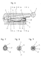
- the adjustment part 3 stands with a threaded bore 11 an adjusting screw 12 (Fig. 1-5 and 10-12) secured in the axial direction in operative connection or is designed as a bolt 13 with a threaded portion 14 which with a in the axial direction secured nut 15 is in operative connection (Fig.6-9).
- the adjustment part 3 consists of a web 5, a connecting web 16 and one connecting to the connecting web 16 at the other end, with a threaded bore 11 executed cross piece 17, wherein in the Threaded bore 11 of the cross piece 17 engages the adjusting screw 12.
- the crosspiece 17 and the connecting web 16 of the adjustment part 3 close an obtuse angle with each other, the free end of the connecting web 16, in the area of the Web 5 connects, essentially in the region of the axis of the threaded bore 11 in Cross piece 17 lies.
- the connecting web runs in the operating position 16 of the adjustment part 3 and the hinge pin 1 these approximately parallel to each other.
- the adjusting screw 12 is provided with a head 20 provided with a tool grip 19 educated. Access to the tool attack 19 is via a bore 35 in one Mounting part 22 possible.
- the head 20 is in a groove 21 of the mounting part 22 with little Game held axially secured.
- This spring 23 is expediently a leaf spring.
- This leaf spring is bent in a U-shape in the example shown, so that the two spring ends on the one hand on the adjusting part 3 and on the other hand on the base 26 of a groove 24 rest in the assembly part 22.
- a coil spring or a torsion spring it would also be conceivable for a minor design change also use a coil spring or a torsion spring.
- the adjustment part 3 is in one in the mounting part 22 in the radial direction towards one side open groove 24 used, the side walls 25 a lateral guide for the adjustment part 3 form.
- the adjustment part 3 as a bolt 13 is also free Engagement area trained, circumferential collar 27 and with one at the other end trained threaded portion 14 executed.
- One placed on the threaded section 14 Nut 15 engages secured against rotation and axially secured with slight play into a groove 21 on the mounting part 10.
- an internal attack 28 for Applying a turning tool provided on the one with a threaded section 14 End of the adjustment part 3 designed as a bolt 13 .
- a spring 23 e.g. a leaf spring can be used to the resilient effect of the adjustment part 3 cause.
- a simply arched leaf spring can be used here.
- the adjustment part 3 is in a pocket-like manner Housing 29 used, which forms the mounting part 22 here.
- the adjustment part 3 extends extending over a width B of more than one hinge pin 1 to be used, however, for this adjustment part 3, a single adjustment arrangement with adjustment screw 12 is provided.
- the adjustment part 3 is on the inner side boundaries 30, 31 of the housing 29 in its adjustment direction and transversely to its adjustment direction held.
- the groove 7 or a corresponding flattening or recess at the free end region of the hinge pin 1 based on the circumference the same only on a partial area, and that in each case in the operating position in the direction towards the adjustment part 3 facing side fully formed.
- a further groove 7 can be formed. This can be particularly useful for doors that open on the left or right Be an advantage, because then only one type of hinge pin 1 is required.
- the construction according to the invention also makes it possible for the adjustment part 3 in the assembly part 22 is pre-assembled and the assembly part 22 on the production side in the frame or the window or door 10 is inserted.
- the mounting part 22 can have a stop collar 32 as a depth stop when inserting into the prepared hole. If there is one such stop collar 32 then there is also the possibility of the mounting part 22nd to be attached additionally or exclusively by means of screws 33.
- the holder according to the invention provides an optimal possibility for effective Adjustment of a hinge pin inserted in a door or in a window, in addition, significantly higher tolerance limits in the manufacture of the holes for receiving the bracket are tolerable without this on the Functionality and adjustability has negative effects.
- the hinge pin can 1 are inserted into the bore 8.
- the web 5 or the collar 27 are by the resilient design of the adjustment part 3 raised so that after the final deep Push in the hinge pin 1 of the web 5 or the collar 27 into the groove can.
- dismantling the hinge pin 1 it only has to about its axis be rotated into a position in which the web 5 or the collar 27 no longer in one Groove 7 can intervene. In this position, the hinge pin 1 can then in the axial direction be pulled out. This is also advantageous because it makes it easier A quick change to take into account a new design in the Hinge parts can be made.
Landscapes
- Engineering & Computer Science (AREA)
- Mechanical Engineering (AREA)
- Hinges (AREA)
Abstract
Description
Claims (22)
- Halterung für einen Scharnierzapfen eines Fenster-, Tür- oder Möbelscharniers, bei der wenigstens ein Scharnierzapfen zumindest in dessen Einsatzstellung formund/oder kraftschlüssig mit einem Verstellteil in Wirkverbindung bringbar ist, wobei der Verstellteil an seinem innen liegenden, der Scharnierachse abgewandten Endbereich wenigstens einen gegenüber dem unmittelbar darauf folgenden Abschnitt vorstehenden Bund, Steg, Zapfen od.dgl. aufweist, wobei am freien Endbereich des zuzuordnenden Scharnierzapfens wenigstens eine quer zur Längsachse desselben ausgerichtete Nut, Abflachung, Ausnehmung od.dgl. ausgebildet ist, und wobei der Verstellteil und der zugeordnete Scharnierzapfen in ihrer Einsatzstellung zumindest an ihren einander zugewandten Bereichen form- und/oder kraftschlüssig direkt miteinander in Wirkverbindung stehen, dadurch gekennzeichnet, dass der Verstellteil (3) mit dem vorstehenden Bund (27), Steg (5), Zapfen od.dgl. in dessen Einsatzstellung federnd in die Nut (7), die Abflachung, die Ausnehmung od.dgl. am Scharnierzapfen (1) eingreift, und dass der Verstellteil (3) über eine Gewindebohrung (11) mit einer in axialer Richtung gesicherten Verstellschraube (12) in Wirkverbindung steht oder als Gewindebolzen (13) ausgeführt ist, der mit einer in axialer Richtung gesicherten Gewindemutter (15) in Wirkverbindung steht.
- Halterung nach Anspruch 1, dadurch gekennzeichnet, dass der Verstellteil (3) aus einem Bund, Steg (5), Zapfen od.dgl., einem Verbindungssteg (16) und einem am anderen Ende an den Verbindungssteg (16) anschließenden, mit einer Gewindebohrung (11) ausgeführten Querstück (17) gebildet ist, wobei in die Gewindebohrung (11) des Querstückes (17) eine Verstellschraube (12) eingreift.
- Halterung nach Anspruch 2, dadurch gekennzeichnet, dass das Querstück (17) und der Verbindungssteg (16) des Verstellteiles (3) einen stumpfen Winkel miteinander einschließen, wobei das freie Ende des Verbindungssteges (16), in dessen Bereich sich der Bund, Steg (5), Zapfen od.dgl. anschließt, im wesentlichen im Bereich der Achse (18) der Gewindebohrung (11) im Querstück (17) liegt.
- Halterung nach Anspruch 3, dadurch gekennzeichnet, dass in der Einsatzstellung des Verbindungssteges (16) des Verstellteiles (3) und des Scharnierzapfens (1) diese annähernd parallel zueinander verlaufend angeordnet sind.
- Halterung nach einem der vorstehenden Ansprüche, dadurch gekennzeichnet, dass die Verstellschraube (12) mit einem mit einem Werkzeugangriff (19) versehenen Kopf (20) ausgebildet ist, welcher in einer Nut (21) eines Montageteiles (22) mit geringfügigem Spiel axial gesichert gehalten ist.
- Halterung nach Anspruch 5, dadurch gekennzeichnet, dass die Verstellschraube (12) samt dem Verstellteil (3) um eine durch den Kopf (20) der Verstellschraube (12) gedachte Querachse in einem geringen Winkelbereich verdrehbar ist.
- Halterung nach einem der Ansprüche 1 bis 6, dadurch gekennzeichnet, dass zwischen dem Verstellteil (3) und einem Montageteil (22) eine Feder (23) eingesetzt ist.
- Halterung nach Anspruch 7, dadurch gekennzeichnet, dass die Feder (23) zwischen dem Verstellteil (3) und dem Montageteil (22) eine Blattfeder ist.
- Halterung nach einem der Ansprüche 1 bis 6, dadurch gekennzeichnet, dass der Verstellteil (3) oder zumindest ein Verbindungssteg (16) desselben aus einem federndem Material gefertigt ist.
- Halterung nach einem der vorstehenden Ansprüche, dadurch gekennzeichnet, dass der Verstellteil (3) in eine in einem Montageteil (22) in radialer Richtung nach einer Seite hin offene Nut (24) eingesetzt ist, deren Seitenwände (25) eine seitliche Führung für den Verstellteil (3) bilden.
- Halterung nach Anspruch 1, dadurch gekennzeichnet, dass der Verstellteil (3) als Bolzen (13) mit am freien Eingriffsbereich ausgebildetem, umlaufenden Bund (27) und mit einem am anderen Ende ausgebildeten Gewindeabschnitt (14) ausgeführt ist, wobei eine auf den Gewindeabschnitt (14) aufgesetzte Mutter (15) verdrehgesichert und mit geringfügigem Spiel axial gesichert in eine Nut (21) am Montageteil (22) eingreift.
- Halterung nach Anspruch 11, dadurch gekennzeichnet, dass an dem mit dem Gewindeabschnitt (14) ausgeführten Ende des als Bolzen (13) ausgebildeten Verstellteiles (3) ein Innenangriff (28) zum Ansetzen eines Drehwerkzeuges vorgesehen ist.
- Halterung nach Anspruch 11, dadurch gekennzeichnet, dass zwischen dem als Bolzen (13) ausgebildeten Verstellteil (3) und dem Montageteil (22) eine Feder (23), z.B. eine Blattfeder, eingesetzt ist.
- Halterung nach einem der vorstehenden Ansprüche, dadurch gekennzeichnet, dass der Verstellteil (3) in ein taschenartiges Gehäuse (29) eingesetzt ist und sich über eine Breite (B) von mehr als einem einzusetzenden Scharnierzapfen (1) erstreckt, wobei für diesen Verstellteil (3) eine einzige Verstellanordnung mit Verstellschraube (12) vorgesehen ist.
- Halterung nach Anspruch 14, dadurch gekennzeichnet, dass der Verstellteil (3) an den Innenseitenbegrenzungen (30,31) des Gehäuses (29) in dessen Verstellrichtung und quer zu dessen Verstellrichtung verschiebbar gehalten ist.
- Halterung nach einem der vorstehenden Ansprüche, dadurch gekennzeichnet, dass zur Aufnahme des Scharnierzapfens (1) und des zugeordneten, in dem Montageteil (22) gehaltenen Verstellteils (3) an einem Rahmen oder einem Fenster oder einer Tür (10) zwei Bohrungen (8,9) ausgebildet sind, welche gegebenenfalls einander tangieren oder ineinander übergehen.
- Halterung nach Anspruch 16, dadurch gekennzeichnet, dass der Scharnierzapfen (1) und der zugeordnete Verstellteil (3) und somit auch die Bohrungen (8,9) zur Aufnahme des Scharnierzapfens (1) und des Montageteiles (22) einen gegen deren Enden hin sich verjüngenden, spitzen Winkel miteinander einschließen.
- Halterung nach einem der vorstehenden Ansprüche, dadurch gekennzeichnet, dass die Nut (7), Abflachung, Ausnehmung od.dgl. am freien Endbereich des Scharnierzapfens (1) bezogen auf den Umfang desselben nur auf einem Teilbereich, und zwar jeweils an der in Einsatzstellung in Richtung zum Verstellteil (3) hin weisenden Seite voll ausgebildet ist.
- Halterung nach Anspruch 18, dadurch gekennzeichnet, dass an der der Einsatzstellung gegenüberliegenden Seite oder zumindest winkelmäßig versetzt zu dieser eine weitere Nut (7), Abflachung, Ausnehmung od.dgl. ausgebildet ist.
- Halterung nach Anspruch 16 oder 17, dadurch gekennzeichnet, dass der Verstellteil (3) in dem Montageteil (22) vormontiert ist und der Montageteil (22) fertigungsseitig in den Rahmen oder das Fenster oder die Tür (10) eingesetzt ist.
- Halterung nach den Ansprüchen 17, 18 oder 20, dadurch gekennzeichnet, dass der Montageteil (22) einen Anschlagbund (32) als Tiefenanschlag beim Einsetzen in die vorbereitete Bohrung (9) aufweist.
- Halterung nach einem der Ansprüche 1 bis 21, dadurch gekennzeichnet, dass der Scharnierzapfen (1) zu dessen freien Ende hin an einer oder an zwei einander gegenüberliegenden Seiten eine schräg abfallende Abflachung (34) aufweist oder konisch verjüngt auslaufend ausgebildet ist.
Applications Claiming Priority (2)
| Application Number | Priority Date | Filing Date | Title |
|---|---|---|---|
| DE10203228 | 2002-01-28 | ||
| DE2002103228 DE10203228C1 (de) | 2002-01-28 | 2002-01-28 | Halterung für einen Scharnierzapfen eines Fenster-, Tür- oder Möbelscharniers |
Publications (2)
| Publication Number | Publication Date |
|---|---|
| EP1331336A2 true EP1331336A2 (de) | 2003-07-30 |
| EP1331336A3 EP1331336A3 (de) | 2006-12-20 |
Family
ID=7713228
Family Applications (1)
| Application Number | Title | Priority Date | Filing Date |
|---|---|---|---|
| EP03001148A Withdrawn EP1331336A3 (de) | 2002-01-28 | 2003-01-21 | Halterung für einen Scharnierzapfen eines Fenster-, Tür- oder Möbelscharniers |
Country Status (2)
| Country | Link |
|---|---|
| EP (1) | EP1331336A3 (de) |
| DE (1) | DE10203228C1 (de) |
Families Citing this family (1)
| Publication number | Priority date | Publication date | Assignee | Title |
|---|---|---|---|---|
| AT519907B1 (de) * | 2017-05-11 | 2020-07-15 | Blum Gmbh Julius | Möbelscharnier |
Citations (1)
| Publication number | Priority date | Publication date | Assignee | Title |
|---|---|---|---|---|
| DE19730143C1 (de) | 1997-07-14 | 1998-11-19 | Sfs Ind Holding Ag | Halterung für Scharnierzapfen eines Fenster-, Tür- oder Möbelscharniers |
Family Cites Families (1)
| Publication number | Priority date | Publication date | Assignee | Title |
|---|---|---|---|---|
| DE19745569C1 (de) * | 1997-10-15 | 1998-11-19 | Sfs Ind Holding Ag | Halterung für Scharnierzapfen eines Fenster-, Tür- oder Möbelscharniers |
-
2002
- 2002-01-28 DE DE2002103228 patent/DE10203228C1/de not_active Expired - Fee Related
-
2003
- 2003-01-21 EP EP03001148A patent/EP1331336A3/de not_active Withdrawn
Patent Citations (1)
| Publication number | Priority date | Publication date | Assignee | Title |
|---|---|---|---|---|
| DE19730143C1 (de) | 1997-07-14 | 1998-11-19 | Sfs Ind Holding Ag | Halterung für Scharnierzapfen eines Fenster-, Tür- oder Möbelscharniers |
Also Published As
| Publication number | Publication date |
|---|---|
| EP1331336A3 (de) | 2006-12-20 |
| DE10203228C1 (de) | 2003-01-02 |
Similar Documents
| Publication | Publication Date | Title |
|---|---|---|
| DE4219681C2 (de) | Einstellbares Abhebescharnier | |
| DE2723850A1 (de) | Moebelscharnier | |
| WO2008083865A1 (de) | Verriegelungsbeschlag und beschlagteilesatz | |
| DE3236719A1 (de) | Klemmverbinder fuer profilleisten | |
| EP1625269B1 (de) | Treibstangengetriebe | |
| EP2754813B1 (de) | Band, insbesondere für Kunststoff-Türen und -Fenster | |
| DE102011006023B3 (de) | Verstellbares Scharnierband | |
| EP2084356B1 (de) | Bandanordnung für türen, fenster oder dergleichen | |
| EP2913465B1 (de) | Bandanordnung für türen, fenster oder dergleichen | |
| DE102004012890B3 (de) | Scharnier zur drehbaren Halterung einer Tür oder eines Fensters an einem Rahmen | |
| DE10203228C1 (de) | Halterung für einen Scharnierzapfen eines Fenster-, Tür- oder Möbelscharniers | |
| DE20010009U1 (de) | Gelenkband für Türen oder Fenster | |
| DE102008036151A1 (de) | Scharnierband mit einer Unterkonstruktion zur Befestigung an einem Türblatt | |
| WO2004085780A1 (de) | Band, insbesondere für dusch- und/oder glastüren | |
| DE10252309B3 (de) | Halterung für Scharnierzapfen eines Fenster-, Tür- oder Möbelscharniers | |
| DE19730143C1 (de) | Halterung für Scharnierzapfen eines Fenster-, Tür- oder Möbelscharniers | |
| DE20014727U1 (de) | Band für Türen, Fenster u.dgl. | |
| EP4375463B1 (de) | Beschlagsteil | |
| EP1922467B1 (de) | Band für türen, fenster oder dergleichen | |
| DE202007016708U1 (de) | Band für Türen, Fenster o.dgl. | |
| CH695831A5 (de) | Scharnier, insbesondere für Türen. | |
| DE9417867U1 (de) | Vorrichtung zum Ausüben bzw. Hervorbringen einer Befestigungsvorspannung oder Andrückkraft auf bzw. an Beschlagteile(n) | |
| EP0790380A1 (de) | Eckscharnier, insbesondere für Drehkipp-Ecklager für Fenster und Türen od. dgl. | |
| DE102004006330A1 (de) | Bau- oder Möbelbeschlag | |
| DE20217852U1 (de) | Band für Türen, Fenster o.dgl. |
Legal Events
| Date | Code | Title | Description |
|---|---|---|---|
| PUAI | Public reference made under article 153(3) epc to a published international application that has entered the european phase |
Free format text: ORIGINAL CODE: 0009012 |
|
| AK | Designated contracting states |
Designated state(s): AT BE BG CH CY CZ DE DK EE ES FI FR GB GR HU IE IT LI LU MC NL PT SE SI SK TR |
|
| AX | Request for extension of the european patent |
Extension state: AL LT LV MK RO |
|
| PUAL | Search report despatched |
Free format text: ORIGINAL CODE: 0009013 |
|
| AK | Designated contracting states |
Kind code of ref document: A3 Designated state(s): AT BE BG CH CY CZ DE DK EE ES FI FR GB GR HU IE IT LI LU MC NL PT SE SI SK TR |
|
| AX | Request for extension of the european patent |
Extension state: AL LT LV MK RO |
|
| 17P | Request for examination filed |
Effective date: 20070613 |
|
| AKX | Designation fees paid |
Designated state(s): AT BE BG CH CY CZ DE DK EE ES FI FR GB GR HU IE IT LI LU MC NL PT SE SI SK TR |
|
| 17Q | First examination report despatched |
Effective date: 20070823 |
|
| GRAP | Despatch of communication of intention to grant a patent |
Free format text: ORIGINAL CODE: EPIDOSNIGR1 |
|
| STAA | Information on the status of an ep patent application or granted ep patent |
Free format text: STATUS: THE APPLICATION IS DEEMED TO BE WITHDRAWN |
|
| 18D | Application deemed to be withdrawn |
Effective date: 20090613 |