EP1331163A2 - Aufbau für Kraftfahrzeuge mit Tragstruktur aus hochfestem Kunststoff - Google Patents
Aufbau für Kraftfahrzeuge mit Tragstruktur aus hochfestem Kunststoff Download PDFInfo
- Publication number
- EP1331163A2 EP1331163A2 EP02027888A EP02027888A EP1331163A2 EP 1331163 A2 EP1331163 A2 EP 1331163A2 EP 02027888 A EP02027888 A EP 02027888A EP 02027888 A EP02027888 A EP 02027888A EP 1331163 A2 EP1331163 A2 EP 1331163A2
- Authority
- EP
- European Patent Office
- Prior art keywords
- structure according
- drive unit
- passenger compartment
- enveloping device
- enveloping
- Prior art date
- Legal status (The legal status is an assumption and is not a legal conclusion. Google has not performed a legal analysis and makes no representation as to the accuracy of the status listed.)
- Granted
Links
Images



Classifications
-
- B—PERFORMING OPERATIONS; TRANSPORTING
- B62—LAND VEHICLES FOR TRAVELLING OTHERWISE THAN ON RAILS
- B62D—MOTOR VEHICLES; TRAILERS
- B62D29/00—Superstructures, understructures, or sub-units thereof, characterised by the material thereof
- B62D29/04—Superstructures, understructures, or sub-units thereof, characterised by the material thereof predominantly of synthetic material
- B62D29/041—Understructures
-
- B—PERFORMING OPERATIONS; TRANSPORTING
- B62—LAND VEHICLES FOR TRAVELLING OTHERWISE THAN ON RAILS
- B62D—MOTOR VEHICLES; TRAILERS
- B62D21/00—Understructures, i.e. chassis frame on which a vehicle body may be mounted
- B62D21/11—Understructures, i.e. chassis frame on which a vehicle body may be mounted with resilient means for suspension, e.g. of wheels or engine; sub-frames for mounting engine or suspensions
-
- B—PERFORMING OPERATIONS; TRANSPORTING
- B62—LAND VEHICLES FOR TRAVELLING OTHERWISE THAN ON RAILS
- B62D—MOTOR VEHICLES; TRAILERS
- B62D21/00—Understructures, i.e. chassis frame on which a vehicle body may be mounted
- B62D21/12—Understructures, i.e. chassis frame on which a vehicle body may be mounted assembled from readily detachable parts
-
- B—PERFORMING OPERATIONS; TRANSPORTING
- B62—LAND VEHICLES FOR TRAVELLING OTHERWISE THAN ON RAILS
- B62D—MOTOR VEHICLES; TRAILERS
- B62D25/00—Superstructure or monocoque structure sub-units; Parts or details thereof not otherwise provided for
- B62D25/08—Front or rear portions
- B62D25/082—Engine compartments
Definitions
- the invention relates to a structure for motor vehicles, in particular Passenger car according to the preamble of claim 1.
- a known motor vehicle comprises a body with a Passenger compartment structure by a front support structure and a rear Support structure is limited. Both supporting structures are made of metallic Trellis frame formed, wherein one of the two support structures is a drive unit receives. Of the passenger compartment structure are bearing-like extensions carried away by storage forks, attached to pipe supports of the supporting structures, be embraced. For fastening the support structures to the passenger compartment structure serve holding means.
- EP 0 295 661 A2 deals with a rear support structure, which is mediated compliant elements is connected to a passenger compartment structure.
- the said Support structure is formed by a tubular frame construction, including upper and lower longitudinal beams or cross beams and support beams running between the latter.
- precautions have been taken to this tubular frame construction Drive unit and suspension links included.
- High-performance category passenger car that has a body with a has two-seat passenger compartment structure.
- This passenger compartment structure consists of a high-strength plastic and is directly connected to a drive unit i.e. without Interposition of a support structure blocked.
- the drive unit is between the Wheel axles, but adjacent to the rear axle - mid-motor arrangement - in the Passenger cars installed.
- the object of the invention is to provide a structure for a motor vehicle with a To create a passenger compartment structure with a drive unit receiving Support structure can be connected in a simple manner. But it should also be ensured that the support structure is characterized by high strength with low weight and can be spatially advantageously integrated into the motor vehicle.
- the Carrying device of the structure as a tubular in cross section Envelope device of the drive unit, comprising an internal combustion engine, clutch and transmission, is formed and firmly connected to a passenger compartment structure.
- the Enveloping device stiffened with straps, the struts taking up no installation space gets along, the drive unit is kept functional and because of high strength especially glass fiber reinforced plastic CFRP - existing, it has a low Weight and outstanding torsional and flexural strength.
- surrounds the enveloping device essentially on all sides outer contours of the drive unit, the is accessible through through openings in the enveloping device and on storage mounts held in place by her. These stock shots are easy to get into the wrapper integrate.
- the enveloping device consists of an upper part and a lower part On the one hand, their manufacture is made easier, and on the other hand, training is made easier Installation of the drive unit facilitated. Finally, there is a possibility Drive unit and the enveloping device as a prefabricated module with the To connect the passenger compartment structure.
- a structure 1 From a motor vehicle or passenger car of the high performance category only a structure 1 is shown, the one made of high-strength plastic, for example existing passenger compartment structure 2 and a support structure 3 comprises.
- the support structure 3 is arranged by means of, for example, screws 4 designed as holding elements rear transverse wall 5 of the passenger compartment structure 2 connected and used for Inclusion of a drive unit 6 and suspension members 7 - Fig.10 -.
- the Drive unit 6 is by an internal combustion engine 8, a clutch and a Gear 9 formed, the internal combustion engine 8 between the wheel axles of Motor vehicle, but adjacent to a rear axle - mid-motor arrangement - extends.
- the support structure 3 extends - seen in the vehicle longitudinal direction A-A - between an adjacent to the transverse wall 5 of the passenger compartment structure 2 Connection area 10 and a rear of a rear of the motor vehicle End region 11 and is designed as an enveloping device 12, which in an interior 13th surrounds at least part of the housing of the drive unit 6 on all sides.
- the Enveloping device 12, through openings forming access to the drive unit 6 14,15,16,17,18,19,20,21,22 and 23 and in its interior 13 free of Querund Longitudinal struts is made of high-strength, in particular glass fiber reinforced plastic - CFRP - manufactured and stiffened with a carrier device 24.
- the carrier device 24 is with cross members 25,26 and 27 and side members 28,29,30,31,32,33 and 34 fitted.
- the crossbeams 25 and 27 run adjacent to the connection region 10 or the end region 11; the cross member 26 extends in a central region of the enveloping device 11, and it is seen between the vehicle longitudinal direction A-A Cross members 25 and 27 arranged.
- the course and dimensioning of the cross beams and the longitudinal beam of the carrier device 24 are on the one hand by the Dimensions of the drive unit 6 and the other from the static and determined dynamic loads that act on the enveloping device 12, wherein for their constructive design the use of iterative and computational measures suitable is.
- the enveloping device 12 has a closing wall 35, which is located in the substantially over the entire height Hg and the entire width Bg of said Envelope extends and is integrated, for example, as a CFRP part in the latter.
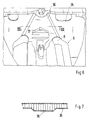
- the closing wall 35 is with a local cross-sectional expansion 36 bearing of a first Suspension bearing 37 of the drive unit 6 provided - Fig. 6 -.
- This Cross-sectional widening 36 is formed in the direction of the drive unit 6 Thickening, extends over the entire height Hg of the closing wall 35 and has an upside down V shape.
- the second reduced width Br begins approximately in one middle section Ab between the connection area 10 and the end area 11 of the Envelope device 12 designed symmetrically to a vehicle longitudinal center plane B-B, approximately where the cross member 26 stiffening them runs; and the reduced width Br remains constant up to the rear end region 11.
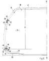
- the enveloping device 12 is formed by an upper part 38 and a lower part 39 - FIG. 5 -.
- the upper part 38 has lateral, upright envelope sections 40 and one horizontally aligned envelope portion 41; the lower part 39 upright envelope sections 42 and a horizontal envelope section 43.
- the length LI of the envelope sections 40 of the upper part 38 is greater than the length LII of the envelope sections 42 of the lower part 39, and the first or second free ends 44 and 45 of the envelope sections 40 and 42 facing each other work together.
- the free ends 44 and 45 are provided with steps 46 and 47, respectively provided at which these ends are assembled, such that removed connections result.
- this longitudinal member comprises a cross section CFRP outer shell 51, a honeycomb structure 52 and an inner shell 53, the one high-strength structure are processed.
- the enveloping device 12 is held on the passenger compartment structure 2 with the screws 4.
- Fig. 4 - For this, e.g. along the outer periphery 54 of the cross member 25 e.g. first console-like tabs 55 and second console-like tabs 56 are provided; the Tabs 55 are replaced by local extensions and tabs 56 Deformations formed in the cross member. 3, the enveloping device 12 - of seen above - on the horizontal section 41, the through opening 16, so is dimensioned that the housing of the drive unit 6 to achieve aesthetic effects visible or accessible for performing maintenance work.
- the Through opening 16 has approximately the shape of a crest-like, isosceles triangle, the tip 57 adjacent to the rear end region 11 lies.
- the through opening 16 guided away from this tip 57 delimiting legs 58,59 have an outward course.
- the wrapping device 12 integrated Includes bearings for suspension members 66 and 67. So it is with the suspension member 66 around a spring-damper unit 68, which by means of a Swivel lever 69 is mounted in the enveloping device 12.
- the pivot lever 69 is on a bearing pin 70 held in a metallic insert 71 of the enveloping device 12 is held by means of a fastening screw 72. That is against it Suspension member 67 a wishbone 73 which is pivotable with a Support pin 74 cooperates.
- the support pin 74 is attached by means of screws 75, 76 metallic inserts 77 held the wrapper 12.
Landscapes
- Engineering & Computer Science (AREA)
- Chemical & Material Sciences (AREA)
- Combustion & Propulsion (AREA)
- Transportation (AREA)
- Mechanical Engineering (AREA)
- Architecture (AREA)
- Structural Engineering (AREA)
- Body Structure For Vehicles (AREA)
- Arrangement Or Mounting Of Propulsion Units For Vehicles (AREA)
Abstract
Description
- Fig. 1
- eine Schrägansicht eines schematisch dargestellten Aufbaus eines Kraftfahrzeugs, und zwar mit einer Fahrgastraumstruktur und einer Tragstruktur,
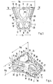
- Fig. 2
- eine Ansicht von oben auf die Tragstruktur mit einem darin schematisch angedeuteten Antriebsaggregat,
- Fig. 3
- eine Ansicht entsprechend Fig. 2, jedoch ohne Anntriebsaggregat,
- Fig. 4
- eine Schrägansicht auf die Tragstruktur von hinten links und oben,
- Fig. 5
- einen Schnitt nach der Linie V-V der Fig. 3,
- Fig. 6
- eine Ansicht schräg von oben auf eine Schließwand der Tragstruktur,
- Fig. 7
- einen Schnitt nach der Linie VII-VII der Fig. 6,
- Fig. 8
- eine Schrägansicht von unten auf ein Oberteil der Tragstruktur,
- Fig. 9
- eine Ansicht von oben auf ein Unterteil der Tragstruktur,
- Fig. 10
- eine Teilansicht der Tragstruktur mit Radaufhängungsgliedern,
- Fig. 11
- einen Schnitt etwa nach der Linie XI-XI der Fig. 9,
- Fig. 12
- einen Schnitt nach der Linie XII-XII der Fig.10,
- Fig. 13
- eine Schrägansicht von hinten auf einen Endbereich der Tragstruktur.
Claims (17)
- Aufbau für Kraftfahrzeuge, insbesondere Personenkraftwagen, mit einer Fahrgastraumstruktur und wenigstens einer daran anschließenden Tragstruktur bspw. zur Aufnahme eines Antriebsaggregats und von Radaufhängungsgliedern, welche Tragstruktur unter Vermittlung von Halteelementen mit der Fahrgastraumstruktur verbunden ist, dadurch gekennzeichnet, dass die einen Anschlussbereich (10) an die Fahrgastraumstruktur (2) und einen hinteren Endbereich (11) aufweisende Tragstruktur (3) als eine mit einer Trägervorrichtung (24) versteifte Hüllvorrichtung (12) aus hochfestem insbesondere glasfaserverstärktem Kunststoff ausgebildet ist, die das Antriebsaggregat (6) zumindest bereichsweise allseitig umgibt, wobei die Hüllvorrichtung (12) mehrere Zugang zum Antriebsaggregat (6) bildende Durchgangsöffnungen (14, 15, 16, 17, 18, 19, 20, 21, 22, 23 und 24) aufweist und mit Lageraufnahmen für das Antriebsaggregat (6) und Radaufhängungsgliedern (66; 67) versehen ist.
- Aufbau nach Anspruch 1, dadurch gekennzeichnet, dass die Hüllvorrichtung (12) benachbart dem Anschlussbereich (10) eine beispielsweise in die Hüllvorrichtung (12) integrierte Schließwand (35) aufweist.
- Aufbau nach Anspruch 2, dadurch gekennzeichnet, dass die Schließwand (35) der Hüllvorrichtung (12) mit einer örtlichen Querschnittserweiterung (36) als Lageraufnahme für das Antriebsaggregat (6) versehen ist.
- Aufbau nach Anspruch 3, dadurch gekennzeichnet, dass die Querschnittserweiterung (36) sich über einen wesentlichen Teil der Höhe der Schließwand (35) erstreckt und bspw. eine auf den Kopf gestellte V-Form besitzt.
- Aufbau nach Anspruch 1, dadurch gekennzeichnet, dass die Hüllvorrichtung (12) - von oben gesehen - sich zwischen dem Anschlussbereich (10) und dem hinteren Endbereich von einer ersten größten Breite (Bg) aus zu einer zweiten reduzierten Breite (Br) hin verjüngt.
- Aufbau nach Anspruch 5, dadurch gekennzeichnet, dass die zweite reduzierte Breite (Br) in einem mittleren Abschnitt (Ab) der Hüllvorrichtung (12) zwischen dem Anschlussbereich (10) und dem Endbereich (11) beginnt, welche zweite reduzierte Breite (Br) etwa konstant zum hinteren Endbereich (11) hin verläuft.
- Aufbau nach Anspruch 1, dadurch gekennzeichnet, dass die Hüllvorrichtung (12) durch ein Oberteil (38) und ein Unterteil (39) gebildet wird.
- Aufbau nach Anspruch 7, dadurch gekennzeichnet, dass zumindest das Oberteil (38) seitliche aufrechte Hüllabschnitte (40) und einen horizontalen Hüllabschnitt (41) aufweist, wobei erste freie Enden (44) des Oberteils (38) mit zweite freien Enden (45) des Unterteils (39) zusammenwirken.
- Aufbau nach Anspruch 8, dadurch gekennzeichnet, dass die ersten freien Enden (44) und zweiten freien Enden (45) mit Stufen (46 und 47) versehen sind, die abgesetzte Verbindungen bilden.
- Aufbau nach einem oder mehreren der vorangehenden Ansprüche, dadurch gekennzeichnet, dass das Oberteil (39) und das Unterteil (39) im Bereich der abgesetzten Verbindungen unter Vermittlung von Schrauben (48) miteinander verbunden sind.
- Aufbau nach Anspruch 1, dadurch gekennzeichnet, dass die Hüllvorrichtung (12) und die Fahrgastraumstruktur (2) im Anschlussbereich (10) unter Vermittlung von mehreren bspw. in Fahrzeuglängsrichtung (A-A) ausgerichteten Schrauben (4) miteinander verbunden sind.
- Aufbau nach Anspruch 11, dadurch gekennzeichnet, dass zumindest ein Teil der Schrauben (4) benachbart eines äußeren Umfangs (54) eines Querträgers (24) der Trägervorrichtung (24) der Hüllvorrichtung (12) vorgesehen sind.
- Aufbau nach Anspruch 12, dadurch gekennzeichnet, dass der Querträger (24) erste und zweite konsolenartige Laschen (55 und 56) zur Aufnahme der Schrauben (4) aufweist.
- Aufbau nach Anspruch 1, dadurch gekennzeichnet, dass - von oben gesehen - eine Durchgangsöffnung (16) der Hüllvorrichtung (12) so bemessen ist, dass Gehäuse des Antriebsaggregats (6) sichtbar und zugänglich sind.
- Aufbau nach den Ansprüchen 1 und 14, dadurch gekennzeichnet, dass die Durchgangsöffnung (16) die Form eines gleichschenkeligen Dreiecks aufweist, dessen Spitze (57) benachbart dem hinteren Endbereich (11) liegt, wobei von der Spitze (57) weggeführte Schenkel (58) des Dreiecks einen nach außen gerichteten bogenförmigen Verlauf aufweisen.
- Aufbau nach Anspruch 1, dadurch gekennzeichnet, dass benachbart dem hinteren Endbereich (11) z.B. an den Längsseiten der Hüllvorrichtung (12) Einformungen (60,61) zur Aufnahme von Lagern (64,65) des Antriebsaggregats (6) vorgesehen sind.
- Aufbau nach Anspruch 16, dadurch gekennzeichnet, dass die Einformungen (60,61) etwa horizontal ausgebildete Stützkonsolen aufweisen, die zur Auflage und Befestigung der Lager (64,65) dienen.
Applications Claiming Priority (2)
| Application Number | Priority Date | Filing Date | Title |
|---|---|---|---|
| DE10202985 | 2002-01-26 | ||
| DE10202985A DE10202985A1 (de) | 2002-01-26 | 2002-01-26 | Aufbau für Kraftfahrzeuge |
Publications (3)
| Publication Number | Publication Date |
|---|---|
| EP1331163A2 true EP1331163A2 (de) | 2003-07-30 |
| EP1331163A3 EP1331163A3 (de) | 2004-02-25 |
| EP1331163B1 EP1331163B1 (de) | 2006-06-07 |
Family
ID=7713103
Family Applications (1)
| Application Number | Title | Priority Date | Filing Date |
|---|---|---|---|
| EP02027888A Expired - Lifetime EP1331163B1 (de) | 2002-01-26 | 2002-12-13 | Aufbau für Kraftfahrzeuge mit Tragstruktur aus hochfestem Kunststoff |
Country Status (4)
| Country | Link |
|---|---|
| US (1) | US6786536B2 (de) |
| EP (1) | EP1331163B1 (de) |
| JP (1) | JP4200016B2 (de) |
| DE (2) | DE10202985A1 (de) |
Cited By (1)
| Publication number | Priority date | Publication date | Assignee | Title |
|---|---|---|---|---|
| EP1661794A1 (de) * | 2004-11-24 | 2006-05-31 | Dr.Ing. h.c.F. Porsche Aktiengesellschaft | Aufbau für Kraftfahrzeuge |
Families Citing this family (14)
| Publication number | Priority date | Publication date | Assignee | Title |
|---|---|---|---|---|
| ITTO20010979A1 (it) * | 2001-10-16 | 2003-04-16 | Ferrari Spa | Scocca per autoveicoli. |
| DE10202985A1 (de) * | 2002-01-26 | 2003-08-07 | Porsche Ag | Aufbau für Kraftfahrzeuge |
| DE10229401A1 (de) * | 2002-06-29 | 2004-01-22 | Dr.Ing.H.C. F. Porsche Ag | Aufbaustruktur für ein Fahrzeug, insbesondere einen Personenkraftwagen |
| DE102005010233B3 (de) * | 2005-03-05 | 2006-10-26 | Daimlerchrysler Ag | Motorgetriebeträger |
| US20080017426A1 (en) * | 2006-03-23 | 2008-01-24 | Walters Raul J | Modular vehicle system and method |
| US20070256882A1 (en) * | 2006-05-05 | 2007-11-08 | Bombardier Recreational Products Inc. | Three-Wheel Vehicle |
| JP4784435B2 (ja) * | 2006-08-08 | 2011-10-05 | トヨタ自動車株式会社 | 車体用一体化繊維強化樹脂製メンバー |
| US20080054597A1 (en) * | 2006-08-31 | 2008-03-06 | Chris Becker | Resilient Skid Plate |
| DE102009017738A1 (de) * | 2009-04-11 | 2010-10-14 | Bayerische Motoren Werke Aktiengesellschaft | Befestigungseinrichtung für ein Kraftfahrzeugaggregat |
| US9440671B2 (en) | 2012-09-20 | 2016-09-13 | Polaris Industries Inc. | Vehicle |
| DE102013217460A1 (de) * | 2013-09-02 | 2015-03-05 | Bayerische Motoren Werke Aktiengesellschaft | Getriebequerträger in Kunststoffbauweise |
| JP2017036019A (ja) * | 2015-08-14 | 2017-02-16 | 本田技研工業株式会社 | 車体構造 |
| US10633028B2 (en) * | 2017-11-22 | 2020-04-28 | Honda Motor Co., Ltd. | Autonomous all-terrain vehicle frame structure |
| CN109835419A (zh) * | 2017-11-24 | 2019-06-04 | 标致雪铁龙汽车股份有限公司 | 一种d柱加强结构及汽车 |
Family Cites Families (26)
| Publication number | Priority date | Publication date | Assignee | Title |
|---|---|---|---|---|
| US2128930A (en) * | 1934-05-18 | 1938-09-06 | Strauch & Hoffman | Unit section automotive vehicle |
| DE767115C (de) * | 1936-03-07 | 1951-10-31 | Auto Union A G | Verfahren zur Herstellung von Wagenkaesten fuer Kraftfahrzeuge |
| GB503514A (en) * | 1936-07-06 | 1939-04-04 | Friedrich Maier | Improvements in or relating to engine mounting for chassisless motor vehicles |
| FR940982A (fr) | 1944-05-27 | 1948-12-29 | Autocostruzioni Diatto | Perfectionnements aux carrosseries mono-bloc |
| US2678231A (en) * | 1948-12-23 | 1954-05-11 | Barenyi Bela | Connecting sleeve for attaching separable vehicle units together |
| US2700570A (en) * | 1948-12-30 | 1955-01-25 | Barenyi Bela | Motor vehicle of three-section, separably connected type |
| US3011796A (en) * | 1956-09-22 | 1961-12-05 | Daimler Benz Ag | Frame construction for motor vehicles |
| US4216839A (en) * | 1978-07-20 | 1980-08-12 | Unique Mobility Inc. | Electrically powered motor vehicle |
| US4422685A (en) * | 1981-07-06 | 1983-12-27 | Bonfilio Paul F | Modular chassis and body for motor vehicles |
| US4573707A (en) * | 1984-01-30 | 1986-03-04 | Pabst Rudolf D | Composite lightweight non-metallic vehicle frame |
| IT1210805B (it) * | 1987-06-16 | 1989-09-29 | Ferrari Eng | Telaio posteriore facente parte di una struttura portante di una autovettura |
| IT1210803B (it) * | 1987-06-16 | 1989-09-29 | Ferrari Eng | Struttura portante di una autovettura |
| US5035397A (en) * | 1988-08-26 | 1991-07-30 | Suzuki Jidosha Kogyo Kabushika Kaisha | Engine mount apparatus |
| US5060975A (en) * | 1988-12-09 | 1991-10-29 | Honda Giken Kogyo Kabushiki Kaisha | Part-mounting structure for vehicle body |
| DE3932196C1 (de) * | 1989-09-27 | 1990-12-13 | Ford-Werke Ag, 5000 Koeln, De | |
| GB9114433D0 (en) * | 1991-07-03 | 1991-08-21 | Jaguar Cars | Motor car structure |
| EP0594131A1 (de) * | 1992-10-21 | 1994-04-27 | The Budd Company | Verbund-Fahrgestell und Herstellungsverfahren |
| US5704644A (en) * | 1993-02-27 | 1998-01-06 | Esoro Ag | Lightweight road vehicle with strengthening structure |
| DE4330044A1 (de) * | 1993-09-06 | 1995-03-09 | Imre Dr Techn Szodfridt | Kompaktwagen mit einer Unterflur-Triebwerkseinheit |
| US5401056A (en) * | 1994-03-11 | 1995-03-28 | Eastman; Clayton | Modular vehicle constructed of front, rear and center vehicular sections |
| GB2317858A (en) * | 1996-10-03 | 1998-04-08 | Rover Group | Vehicle body structure |
| US6003935A (en) * | 1996-12-27 | 1999-12-21 | Dana Corporation | Modular vehicle frame assembly |
| US5960901A (en) * | 1997-09-04 | 1999-10-05 | Corbin Pacific, Inc. | Battery-powered vehicle |
| DE19860794A1 (de) * | 1998-12-30 | 2000-07-06 | Volkswagen Ag | Variables Karosseriebaukonzept für Fahrzeugkarosserien |
| DE10202957A1 (de) * | 2002-01-26 | 2003-08-07 | Porsche Ag | Aufbau für Kraftfahrzeuge |
| DE10202985A1 (de) * | 2002-01-26 | 2003-08-07 | Porsche Ag | Aufbau für Kraftfahrzeuge |
-
2002
- 2002-01-26 DE DE10202985A patent/DE10202985A1/de not_active Withdrawn
- 2002-12-13 EP EP02027888A patent/EP1331163B1/de not_active Expired - Lifetime
- 2002-12-13 DE DE50207095T patent/DE50207095D1/de not_active Expired - Lifetime
-
2003
- 2003-01-27 US US10/351,578 patent/US6786536B2/en not_active Expired - Lifetime
- 2003-01-27 JP JP2003017847A patent/JP4200016B2/ja not_active Expired - Fee Related
Cited By (1)
| Publication number | Priority date | Publication date | Assignee | Title |
|---|---|---|---|---|
| EP1661794A1 (de) * | 2004-11-24 | 2006-05-31 | Dr.Ing. h.c.F. Porsche Aktiengesellschaft | Aufbau für Kraftfahrzeuge |
Also Published As
| Publication number | Publication date |
|---|---|
| US20030168887A1 (en) | 2003-09-11 |
| DE50207095D1 (de) | 2006-07-20 |
| JP4200016B2 (ja) | 2008-12-24 |
| US6786536B2 (en) | 2004-09-07 |
| DE10202985A1 (de) | 2003-08-07 |
| EP1331163A3 (de) | 2004-02-25 |
| JP2003246281A (ja) | 2003-09-02 |
| EP1331163B1 (de) | 2006-06-07 |
Similar Documents
| Publication | Publication Date | Title |
|---|---|---|
| EP1490256B1 (de) | Kraftfahrzeug | |
| DE3812431C2 (de) | ||
| EP1924486B1 (de) | Vorderachsträger, insbesondere für kraftfahrzeuge | |
| EP1331163B1 (de) | Aufbau für Kraftfahrzeuge mit Tragstruktur aus hochfestem Kunststoff | |
| EP2415654B1 (de) | Hilfsrahmen für Kraftfahrzeuge | |
| EP1331162B1 (de) | Aufbau für Kraftfahrzeuge mit Tragstruktur aus hochfestem Kunststoff | |
| DE4322717A1 (de) | Rahmen für Nutzfahrzeuge | |
| EP2159135B1 (de) | Nutzfahrzeugrahmen mit modularem Multifunktionslagerblock | |
| DE102012111461A1 (de) | Hilfsrahmen für ein Kraftfahrzeug | |
| DE10202956B4 (de) | Tragstruktur für ein Antriebsaggregat eines Kraftfahrzeugs | |
| EP3696056B1 (de) | Fahrzeug-chassis-modul mit fahrzeug-achse und anschlussknoten | |
| EP2729349B1 (de) | Fahrzeug sowie verfahren zur montage eines antriebsaggregats | |
| DE3942794C2 (de) | ||
| DE8704697U1 (de) | Rahmenkonstruktion für Motorrad | |
| EP2113404B1 (de) | Kraftfahrzeug mit Anhängekupplung | |
| DE102008028351B4 (de) | Fahrwerksbauteil | |
| DE3151280C2 (de) | Fahrgestellrahmen für Fahrzeuge, insbesondere Omnibusse | |
| DE102005003296B4 (de) | Rumpfhecksektion eines Flugzeugs | |
| DE102016006848A1 (de) | Achsträger für ein mehrspuriges Kraftfahrzeug | |
| EP0940319A2 (de) | Fahrgestell eines schweren Nutzfahrzeuges | |
| DE10260393B4 (de) | Tunnelstruktur | |
| DE4322716A1 (de) | Rahmen für Nutzfahrzeuge | |
| DE102005061417A1 (de) | Hilfsrahmen für ein Kraftfahrzeug | |
| DE102004055197A1 (de) | Tunnelbrücke für ein Kraftfahrzeug | |
| DE102006047511A1 (de) | Achssystem |
Legal Events
| Date | Code | Title | Description |
|---|---|---|---|
| PUAI | Public reference made under article 153(3) epc to a published international application that has entered the european phase |
Free format text: ORIGINAL CODE: 0009012 |
|
| AK | Designated contracting states |
Designated state(s): AT BE BG CH CY CZ DE DK EE ES FI FR GB GR IE IT LI LU MC NL PT SE SI SK TR |
|
| AX | Request for extension of the european patent |
Extension state: AL LT LV MK RO |
|
| PUAL | Search report despatched |
Free format text: ORIGINAL CODE: 0009013 |
|
| AK | Designated contracting states |
Kind code of ref document: A3 Designated state(s): AT BE BG CH CY CZ DE DK EE ES FI FR GB GR IE IT LI LU MC NL PT SE SI SK TR |
|
| AX | Request for extension of the european patent |
Extension state: AL LT LV MK RO |
|
| 17P | Request for examination filed |
Effective date: 20040825 |
|
| AKX | Designation fees paid |
Designated state(s): DE FR GB IT |
|
| GRAP | Despatch of communication of intention to grant a patent |
Free format text: ORIGINAL CODE: EPIDOSNIGR1 |
|
| GRAS | Grant fee paid |
Free format text: ORIGINAL CODE: EPIDOSNIGR3 |
|
| GRAA | (expected) grant |
Free format text: ORIGINAL CODE: 0009210 |
|
| AK | Designated contracting states |
Kind code of ref document: B1 Designated state(s): DE FR GB IT |
|
| REG | Reference to a national code |
Ref country code: GB Ref legal event code: FG4D Free format text: NOT ENGLISH |
|
| REF | Corresponds to: |
Ref document number: 50207095 Country of ref document: DE Date of ref document: 20060720 Kind code of ref document: P |
|
| GBT | Gb: translation of ep patent filed (gb section 77(6)(a)/1977) |
Effective date: 20060921 |
|
| ET | Fr: translation filed | ||
| PLBE | No opposition filed within time limit |
Free format text: ORIGINAL CODE: 0009261 |
|
| STAA | Information on the status of an ep patent application or granted ep patent |
Free format text: STATUS: NO OPPOSITION FILED WITHIN TIME LIMIT |
|
| 26N | No opposition filed |
Effective date: 20070308 |
|
| REG | Reference to a national code |
Ref country code: FR Ref legal event code: TP |
|
| REG | Reference to a national code |
Ref country code: FR Ref legal event code: CD |
|
| PGFP | Annual fee paid to national office [announced via postgrant information from national office to epo] |
Ref country code: FR Payment date: 20110104 Year of fee payment: 9 |
|
| REG | Reference to a national code |
Ref country code: FR Ref legal event code: TP |
|
| PGFP | Annual fee paid to national office [announced via postgrant information from national office to epo] |
Ref country code: GB Payment date: 20101221 Year of fee payment: 9 |
|
| REG | Reference to a national code |
Ref country code: GB Ref legal event code: 732E Free format text: REGISTERED BETWEEN 20110310 AND 20110316 |
|
| REG | Reference to a national code |
Ref country code: GB Ref legal event code: 732E Free format text: REGISTERED BETWEEN 20110331 AND 20110406 |
|
| GBPC | Gb: european patent ceased through non-payment of renewal fee |
Effective date: 20111213 |
|
| REG | Reference to a national code |
Ref country code: FR Ref legal event code: ST Effective date: 20120831 |
|
| PG25 | Lapsed in a contracting state [announced via postgrant information from national office to epo] |
Ref country code: GB Free format text: LAPSE BECAUSE OF NON-PAYMENT OF DUE FEES Effective date: 20111213 |
|
| PG25 | Lapsed in a contracting state [announced via postgrant information from national office to epo] |
Ref country code: FR Free format text: LAPSE BECAUSE OF NON-PAYMENT OF DUE FEES Effective date: 20120102 |
|
| PGFP | Annual fee paid to national office [announced via postgrant information from national office to epo] |
Ref country code: DE Payment date: 20151207 Year of fee payment: 14 |
|
| PGFP | Annual fee paid to national office [announced via postgrant information from national office to epo] |
Ref country code: IT Payment date: 20151228 Year of fee payment: 14 |
|
| REG | Reference to a national code |
Ref country code: DE Ref legal event code: R119 Ref document number: 50207095 Country of ref document: DE |
|
| PG25 | Lapsed in a contracting state [announced via postgrant information from national office to epo] |
Ref country code: IT Free format text: LAPSE BECAUSE OF NON-PAYMENT OF DUE FEES Effective date: 20161213 |
|
| PG25 | Lapsed in a contracting state [announced via postgrant information from national office to epo] |
Ref country code: DE Free format text: LAPSE BECAUSE OF NON-PAYMENT OF DUE FEES Effective date: 20170701 |