EP1330029A2 - Verfahren zur digitalen Filterung eines mit Rauschen behafteten Signals und Regelungssystem für ein Fahrzeug - Google Patents
Verfahren zur digitalen Filterung eines mit Rauschen behafteten Signals und Regelungssystem für ein Fahrzeug Download PDFInfo
- Publication number
- EP1330029A2 EP1330029A2 EP02026740A EP02026740A EP1330029A2 EP 1330029 A2 EP1330029 A2 EP 1330029A2 EP 02026740 A EP02026740 A EP 02026740A EP 02026740 A EP02026740 A EP 02026740A EP 1330029 A2 EP1330029 A2 EP 1330029A2
- Authority
- EP
- European Patent Office
- Prior art keywords
- signal
- filter
- vehicle
- zero crossing
- filtered
- Prior art date
- Legal status (The legal status is an assumption and is not a legal conclusion. Google has not performed a legal analysis and makes no representation as to the accuracy of the status listed.)
- Withdrawn
Links
- 238000000034 method Methods 0.000 title claims description 25
- 238000001914 filtration Methods 0.000 title claims description 22
- 230000003044 adaptive effect Effects 0.000 claims description 8
- 238000013016 damping Methods 0.000 claims description 7
- 238000004590 computer program Methods 0.000 claims description 3
- 238000005070 sampling Methods 0.000 description 21
- 238000013213 extrapolation Methods 0.000 description 6
- 230000006870 function Effects 0.000 description 5
- 238000005259 measurement Methods 0.000 description 5
- 230000010363 phase shift Effects 0.000 description 5
- 238000012360 testing method Methods 0.000 description 5
- 238000004364 calculation method Methods 0.000 description 4
- 238000011161 development Methods 0.000 description 3
- 230000006978 adaptation Effects 0.000 description 2
- 238000004422 calculation algorithm Methods 0.000 description 2
- 238000001514 detection method Methods 0.000 description 2
- 238000010586 diagram Methods 0.000 description 2
- 238000013459 approach Methods 0.000 description 1
- 230000001419 dependent effect Effects 0.000 description 1
- 230000000694 effects Effects 0.000 description 1
- 238000012886 linear function Methods 0.000 description 1
- 230000010355 oscillation Effects 0.000 description 1
- 230000004044 response Effects 0.000 description 1
- 230000001953 sensory effect Effects 0.000 description 1
Images



Classifications
-
- H—ELECTRICITY
- H03—ELECTRONIC CIRCUITRY
- H03H—IMPEDANCE NETWORKS, e.g. RESONANT CIRCUITS; RESONATORS
- H03H17/00—Networks using digital techniques
- H03H17/02—Frequency selective networks
- H03H17/0294—Variable filters; Programmable filters
-
- H—ELECTRICITY
- H03—ELECTRONIC CIRCUITRY
- H03H—IMPEDANCE NETWORKS, e.g. RESONANT CIRCUITS; RESONATORS
- H03H17/00—Networks using digital techniques
- H03H17/02—Frequency selective networks
- H03H17/0248—Filters characterised by a particular frequency response or filtering method
- H03H17/028—Polynomial filters
-
- H—ELECTRICITY
- H03—ELECTRONIC CIRCUITRY
- H03H—IMPEDANCE NETWORKS, e.g. RESONANT CIRCUITS; RESONATORS
- H03H17/00—Networks using digital techniques
- H03H17/02—Frequency selective networks
- H03H17/06—Non-recursive filters
-
- H—ELECTRICITY
- H03—ELECTRONIC CIRCUITRY
- H03H—IMPEDANCE NETWORKS, e.g. RESONANT CIRCUITS; RESONATORS
- H03H17/00—Networks using digital techniques
- H03H17/02—Frequency selective networks
- H03H17/0294—Variable filters; Programmable filters
- H03H2017/0297—Coefficients derived from input parameters
Definitions
- the invention relates to a method for digitally filtering a noise-laden one Signal for filtering out the noise component, in particular around a zero crossing of the Determine signal, and a method for controlling the driving dynamics of a vehicle and a corresponding computer program and control system.
- DE 41 12 007 A1 describes a system for forming a signal for the Chassis control of a vehicle known in which the relative movements between Vehicle body and wheels are recorded. The predicted is based on this Spring speed determined at a future point in time. Based on that the control of a vehicle size, such as the control of adjustable Dampers. The goal here is to adjust the Damper characteristics in operating phases of low damping forces of the damper to minimize the adjustment noise of the damping.
- the invention is therefore based on the object of an improved method for digital Filtering a signal with noise to filter out the noise component create and an improved method for controlling the driving dynamics of a vehicle and a corresponding computer program and control system.
- a particular advantage of the invention is that the filtered signal is only a small one or no phase shift with respect to the unfiltered noise Signal. This is particularly true for the filtering of the linearly approximated one Waveform too, so the time of passage of the noisy Signal by a certain signal level by evaluating the filtered signal can be determined particularly precisely. In this way, the The exact time of the zero crossing can be determined.
- Another particular advantage of the invention is that an FIR filter (Finit Impulse Response) can be used so that the filter is stable in any case.
- FIR filter Frinit Impulse Response
- an FIR filter is a certain filter length used, which is much smaller than the period of Is the fundamental frequency of the signal to be filtered.
- the filter length is 1/5 or chosen as a 1/10 of the period of the fundamental frequency.
- the filtering takes place by interpolation based on past samples within a by the Filter length given window length.
- the filtering takes place by extrapolation based on the same samples to extrapolate to a future signal value. Extrapolation can be used in particular for this will estimate future signal values, for example the zero crossing, or Calculate signal values for certain past or future times.
- the filtering takes place a non-linear signal component, for example a quadratic or higher order.
- A is used to filter out signal components of quadratic order quadratic interpolation algorithm used to match corresponding nonlinear Filter out signal profiles.
- the filter length selected so that the signal curve of the filtering signal within a relevant range a substantially linear Has course. In the case of a vibration signal, this applies to the area around the Zero crossing of the signal, which can be approximated by a linear function.
- the invention Digital filtering method as the basis for the regulation of one or more vehicle dynamic parameters used. For example for the regulation of At certain sampling times, the input signals from Level sensors detected and the corresponding signal with noise filtered and fed to the control algorithm. For example, the Damper characteristic adaptively based on the detection of the zero crossing of the Signal.
- the filtered signal value i.e. H. the output of filter 1 is designated q (n).
- the filter parameters a 0 (n) and a 1 (n) are recalculated for each calculation of a filtered signal value q (n).
- the adaptation unit 2 which has a memory 3 and a computer 4, is used for this purpose.
- the memory 3 serves to store current and past sampling times x (n), x (n-1), ..., x (nK) and past sampling values of the noisy signal y (n), y (n-1), ..., y (nK).
- K past sampling times and sampling values are therefore stored. This also corresponds to a filter length of K, ie the filter length results from KT s , where T s is the sampling time.
- the filter parameters a 0 and a 1 are determined with the computer 4 for the calculation of the n-th filtered signal value q (n).
- the longest previous sampling times x (nK) and sampling values y (nK) are deleted from the memory 3 and the current sampling time x (n + 1) and sample value y (n + 1) are shifted into the memory 3, so that the filter parameters a 0 and a 1 are calculated in the computer 4 based on this adapted set of previous sampling times and sampling values.
- a linear signal component is made from the sampled values filtered out y (n) of the noisy signal.
- the filtered signal value q (n) at The nth point in time results from the past sampling times by interpolation and samples of the filter length.
- the future signal value q (n + i) can also be calculated by extrapolation.
- the filter parameters a 0 and a 1 at the nth time are used for this. This means that the filtered signal value q (n + i) results from extrapolation, based on the sampling times and sampling values behind the nth point in time.
- the filter function of filter 1 be expanded accordingly.
- a Filter function in the form of a m-th order polynomial required for filtering out signal components of the mth order.
- filter parameters a 0 and a 1 can be calculated by computer 4 based on the previous sampling times x and sampling values y stored in memory 3 as follows: in which
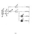
- FIG. 2 shows a test system to illustrate the effect of the filter 1 in FIG Figure 1.
- the test system includes a signal generator 5 for generating a sinusoidal signal. This sinusoidal signal is in the amplifier 6 with the Gain factor 1 weighted and sampled by the analog-digital converter 7. from that the reference signal "reference" results.
- the test system also has a noise generator 8.
- the noise generated by the noise generator 8 generated noise is weighted by the amplifier 9 by a factor of 0.1.
- the Output signals of the amplifiers 6 and 9 are added up in the summer 10 and then sampled by the analog-digital converter 11. From this it follows that "Measurement signal" designated signal. This corresponds to one from a sensor e.g. in one Motor vehicle emitted signal with noise.
- the measurement signal with noise is fed to the adaptive filter 12, which in Structure and mode of operation corresponds to the filter explained with reference to FIG. 1.
- the "measurement signal” is also in one Low pass filter 13 entered.
- This low-pass filter 13 is one in itself Butterworth filters known from the prior art.
- FIG. 3 That with noise Measurement signal with a signal is denoted in the figure as signal 14.
- the output signal of the Butterworth filter 13 is designated by 15 in FIG.
- the reference signal is in the Figure 3 designated 16 and the output signal of the filter 12 "Adaptive" is in the Figure 3 designated 17.
- the signals 17 and 16 are largely congruent, in particular in the area around the zero crossing, so that the time of the zero crossing t 0 of the filtered signal 17 coincides with that of the reference signal 16.
- the signal 15, ie the output signal of the Butterworth low-pass filter 13 has a clear phase shift compared to the reference signal.
- the signal 15 crosses zero at a time t B significantly after the actual zero crossing at the time t 0 .
- the adaptively filtered signal 17 is superior to the Butterworth filtered signal 15 and has a better approximation to the reference signal 16, in particular a smaller phase shift.
- FIG. 4 shows an embodiment of the control method according to the invention.
- a noisy signal is input which for example comes from a sensor.
- This signal is generated by a filter in the Figure 1 filtered type, namely by adaptive interpolation, based on a Window of past values of filter length K.
- the correspondingly filtered signal is output in step 42.
- step 43 a zero crossing is determined for the filtered signal.
- the time of Zero crossing of the filtered signal is fed to a control in step 44, which regulates, for example, the damping of a Vehicle damper.
- step 43 the zero crossing
- step 44 the control be used in step 44.
- FIG. 5 shows an application of the digital filtering method according to the invention for a motor vehicle 18.
- the motor vehicle 18 has a damper 20 on each wheel 19.
- the level of the damper 20 is detected by a sensor 21, which is a outputs the corresponding output signal. This output signal typically shows Noise components.
- the output signal of the sensor 21 is input into a filter 22, which corresponds in structure and mode of operation to the filter of FIG. 1.
- the filter 22 output filtered signal value is input to the zero crossing detector 23 which based on this the current and / or future zero crossing of the signal is determined.
- the current and / or future point in time of the zero crossing is determined by the Zero crossing detector 23 entered in the damping control 24, the corresponding adjusts one or more damping parameters of the damper 20.
- This method can also be applied analog to signal levels other than that Detect zero crossing.
Landscapes
- Physics & Mathematics (AREA)
- Mathematical Physics (AREA)
- Engineering & Computer Science (AREA)
- Computer Hardware Design (AREA)
- Pure & Applied Mathematics (AREA)
- General Physics & Mathematics (AREA)
- Algebra (AREA)
- Feedback Control In General (AREA)
- Vibration Prevention Devices (AREA)
- Soundproofing, Sound Blocking, And Sound Damping (AREA)
- Fittings On The Vehicle Exterior For Carrying Loads, And Devices For Holding Or Mounting Articles (AREA)
- Analogue/Digital Conversion (AREA)
- Noise Elimination (AREA)
- Vehicle Body Suspensions (AREA)
Abstract
Description
- Figur 1
- ein Blockdiagramm einer Ausführungsform eines erfindungsgemäßen digitalen Filters,
- Figur 2
- ein Blockdiagramm eines Testsystems zur Veranschaulichung der Wirkungsweise des erfindungsgemäßen digitalen Filters,
- Figur 3
- die Verläufe von Signalen in dem Testsystem der Figur 2,
- Figur 4
- eine Ausführungsform des erfindungsgemäßen Verfahrens zur Durchführung einer Regelung basierend auf einer Erkennung des Nulldurchgangs,
- Figur 5
- eine Ausführungsform des erfindungsgemäßen Regelungssystems für ein Kraftfahrzeug.



- Filter
- 1
- Adaptionseinheit
- 2
- Speicher
- 3
- Rechner
- 4
- Signalgenerator
- 5
- Verstärker
- 6
- Analog-Digital Wandler
- 7
- Rauschgenerator
- 8
- Verstärker
- 9
- Summierer
- 10
- Analog-Digital Wandler
- 11
- Filter
- 12
- Filter
- 13
- Signal
- 14
- Signal
- 15
- Signal
- 16
- Signal
- 17
- Kraftfahrzeug
- 18
- Rad
- 19
- Dämpfer
- 20
- Sensor
- 21
- Filter
- 22
- Nulldurchgangsdetektor
- 23
- Dämpfungsregelung
- 24
- Schritt
- 40
- Schritt
- 42
- Schritt
- 43
- Schritt
- 44
Claims (13)
- Verfahren zur digitalen Filterung eines mit Rauschen behafteten Signals zur Ausfilterung des Rauschanteils mit folgenden Schritten:Eingabe des Signals in einen digitalen Filter einer Filterlänge (K), wobei die Filterlänge kleiner als die Periode der Grundfrequenz des Signals ist,Ausfilterung eines Signalanteils einer Ordnung (m) aus dem Signal, basierend auf zurückliegenden Abtastwerten des Signals innerhalb der Filterlänge,Ausgabe eines gefilterten Signalwerts.
- Verfahren nach Anspruch 1, wobei die Filterlänge weniger als 1/4, vorzugsweise weniger als 1/5, insbesondere 1/10 der Periode der Grundfrequenz des Signals beträgt.
- Verfahren nach Anspruch 1 oder 2, wobei es sich bei dem gesuchten Signalanteil um einen linearen Signalanteil handelt.
- Verfahren nach Anspruch 1, 2 oder 3, wobei es sich bei dem gefilterten Signalwert um einen aus den zurückliegenden Abtastwerten interpolierten Signalwert handelt.
- Verfahren nach Anspruch 1, 2 oder 3, wobei es sich bei dem gefilterten Signalwert um einen aus den zurückliegenden Abtastwerten extrapolierten Signalwert handelt.
- Verfahren nach einem der vorhergehenden Ansprüche 1 bis 5, wobei das Signal (y) zu diskreten Zeitpunkten (x (n)) abgetastet wird und wobei ein linearer adaptiver Filter für die Ausfilterung des Signalanteils verwendet wird, und zur Berechnung der Filterkoeffizienten des linearen adaptiven Filters auf einen Speicher zugegriffen wird, der die zurückliegenden Abtastwerte und diskreten Zeitpunkte innerhalb der Filterlänge (K) beinhaltet.
- Verfahren nach einem der vorhergehenden Ansprüche 1 bis 6, wobei ein Nulldurchgang des mit Rauschen behafteten Signals mittels der gefilterten Signalwerte bestimmt wird.
- Verfahren nach einem der vorhergehenden Ansprüche 1 bis 7, wobei es sich bei dem mit Rauschen behafteten Signal um das Ausgangssignal eines Sensors für ein Schwingungssystem, z. B. eines Fahrzeugs, handelt.
- Verfahren zur Regelung der Fahrdynamik eines Fahrzeugs mit folgenden Schritten:Filterung eines Ausgangssignals eines Sensors zur Erfassung einer Schwingung des Fahrzeugs nach einem Verfahren nach einem der vorhergehenden Ansprüche 1 bis 8,Bestimmung des Zeitpunkts der Erreichung eines vorgegebenen Werts des Ausgangssignals, insbesondere des Nulldurchgangs, mittels der gefilterten Signalwerte,Regelung eines oder mehrerer fahrdynamischer Parameter des Fahrzeugs basierend auf dem Zeitpunkt.
- Verfahren nach Anspruch 9, wobei es sich bei dem Parameter um die Dämpfung eines Dämpfers des Fahrzeug handelt.
- Computerprogrammprodukt zur Durchführung eines Verfahren nach einem der vorhergehenden Ansprüche 1 bis 10.
- Regelungssystem für ein oder mehrere fahrdynamische Parameter eines Fahrzeugs mitzumindest einem Sensor (21) zur Erfassung einer Schwingung des Fahrzeugs oder eines Fahrzeugteils,Rechnermitteln (22, 23) zur Durchführung eines Verfahrens zur digitalen Filterung des Sensorausgangsignals nach einem der vorhergehenden Ansprüche 1 bis 8 und zur Bestimmung des Zeitpunkts der Erreichung eines vorgegebenen Werts des Ausgangssignals, insbesondere des Nulldurchgangs, aus dem gefilterten Signalwert,Regelungsmitteln (24) zur Anpassung des oder der fahrdynamischen Parameter basierend auf der Bestimmung des Nulldurchgangs.
- Regelungssystem nach Anspruch 12, wobei es sich bei dem Parameter um die Dämpfung eines Dämpfers (20) des Fahrzeugs handelt.
Applications Claiming Priority (2)
| Application Number | Priority Date | Filing Date | Title |
|---|---|---|---|
| DE10201902 | 2002-01-19 | ||
| DE10201902A DE10201902B4 (de) | 2002-01-19 | 2002-01-19 | Verfahren zur digitalen Filterung eines mit Rauschen behafteten Signals und Regelungssystem für ein Fahrzeug |
Publications (2)
| Publication Number | Publication Date |
|---|---|
| EP1330029A2 true EP1330029A2 (de) | 2003-07-23 |
| EP1330029A3 EP1330029A3 (de) | 2005-08-17 |
Family
ID=7712523
Family Applications (1)
| Application Number | Title | Priority Date | Filing Date |
|---|---|---|---|
| EP02026740A Withdrawn EP1330029A3 (de) | 2002-01-19 | 2002-11-30 | Verfahren zur digitalen Filterung eines mit Rauschen behafteten Signals und Regelungssystem für ein Fahrzeug |
Country Status (3)
| Country | Link |
|---|---|
| US (1) | US6647324B2 (de) |
| EP (1) | EP1330029A3 (de) |
| DE (1) | DE10201902B4 (de) |
Families Citing this family (9)
| Publication number | Priority date | Publication date | Assignee | Title |
|---|---|---|---|---|
| US7447279B2 (en) * | 2005-01-31 | 2008-11-04 | Freescale Semiconductor, Inc. | Method and system for indicating zero-crossings of a signal in the presence of noise |
| DE102009011693A1 (de) * | 2008-10-22 | 2010-04-29 | Continental Teves Ag & Co. Ohg | Verfahren und zugehörige Filtervorrichtung zur Filterung eines mit Rauschen behafteten Eingangssignals |
| US8452599B2 (en) * | 2009-06-10 | 2013-05-28 | Toyota Motor Engineering & Manufacturing North America, Inc. | Method and system for extracting messages |
| US8269616B2 (en) * | 2009-07-16 | 2012-09-18 | Toyota Motor Engineering & Manufacturing North America, Inc. | Method and system for detecting gaps between objects |
| US8337160B2 (en) * | 2009-10-19 | 2012-12-25 | Toyota Motor Engineering & Manufacturing North America, Inc. | High efficiency turbine system |
| US8237792B2 (en) | 2009-12-18 | 2012-08-07 | Toyota Motor Engineering & Manufacturing North America, Inc. | Method and system for describing and organizing image data |
| US8424621B2 (en) | 2010-07-23 | 2013-04-23 | Toyota Motor Engineering & Manufacturing North America, Inc. | Omni traction wheel system and methods of operating the same |
| US8880289B2 (en) | 2011-03-17 | 2014-11-04 | Toyota Motor Engineering & Manufacturing North America, Inc. | Vehicle maneuver application interface |
| US8855847B2 (en) | 2012-01-20 | 2014-10-07 | Toyota Motor Engineering & Manufacturing North America, Inc. | Intelligent navigation system |
Citations (1)
| Publication number | Priority date | Publication date | Assignee | Title |
|---|---|---|---|---|
| DE4112007A1 (de) | 1991-04-12 | 1992-10-15 | Bosch Gmbh Robert | System zur bildung eines signals bei einem fahrzeug |
Family Cites Families (5)
| Publication number | Priority date | Publication date | Assignee | Title |
|---|---|---|---|---|
| JP2876874B2 (ja) * | 1992-03-04 | 1999-03-31 | 日産自動車株式会社 | 車両用能動型騒音制御装置 |
| NO175798C (no) * | 1992-07-22 | 1994-12-07 | Sinvent As | Fremgangsmåte og anordning til aktiv stöydemping i et lokalt område |
| JPH08166788A (ja) * | 1994-12-14 | 1996-06-25 | Nissan Motor Co Ltd | 能動型騒音制御装置及び能動型振動制御装置 |
| DE19534996A1 (de) * | 1995-09-21 | 1997-03-27 | Bosch Gmbh Robert | Verfahren zur Verbrennungsaussetzererkennung durch Auswertung von Drehzahlschwankungen |
| US6185300B1 (en) * | 1996-12-31 | 2001-02-06 | Ericsson Inc. | Echo canceler for use in communications system |
-
2002
- 2002-01-19 DE DE10201902A patent/DE10201902B4/de not_active Expired - Fee Related
- 2002-11-30 EP EP02026740A patent/EP1330029A3/de not_active Withdrawn
-
2003
- 2003-01-21 US US10/347,316 patent/US6647324B2/en not_active Expired - Fee Related
Patent Citations (1)
| Publication number | Priority date | Publication date | Assignee | Title |
|---|---|---|---|---|
| DE4112007A1 (de) | 1991-04-12 | 1992-10-15 | Bosch Gmbh Robert | System zur bildung eines signals bei einem fahrzeug |
Also Published As
| Publication number | Publication date |
|---|---|
| EP1330029A3 (de) | 2005-08-17 |
| DE10201902B4 (de) | 2007-01-11 |
| US20030139856A1 (en) | 2003-07-24 |
| DE10201902A1 (de) | 2003-08-14 |
| US6647324B2 (en) | 2003-11-11 |
Similar Documents
| Publication | Publication Date | Title |
|---|---|---|
| DE4121628C2 (de) | Digital-Tonfrequenz-Entzerrer | |
| EP1330029A2 (de) | Verfahren zur digitalen Filterung eines mit Rauschen behafteten Signals und Regelungssystem für ein Fahrzeug | |
| DE102018105087B3 (de) | System, Verfahren und Computerprogrammprodukt zur Erfassung physikalischer Größen von mindestens einer Komponente eines Stufentransformators und zum Monitoring der Komponenten eines Stufentransformators | |
| EP3407073B1 (de) | Verfahren und system zur digitalen triggerung für oszilloskope | |
| DE69414683T2 (de) | Verfahren und Vorrichtung zur automatischen Verstärkungsregelung in einem digitalen Empfänger und damit ausgerüsteter Empfänger | |
| US5463346A (en) | Fast response low-pass filter | |
| EP0602780B1 (de) | Digitale Verarbeitung und Filterung von Signalen | |
| EP2016428B1 (de) | Verfahren und vorrichtung zur digitalen triggerung eines mit einem rauschsignal überlagerten messsignals | |
| DE102013217093B4 (de) | Verfahren zum Anpassen der Parameter eines Reglers für mikromechanische Aktoren und Vorrichtung | |
| DE102019109892B3 (de) | Sensorschaltung und Verfahren zum Filtern eines Sensorsignals | |
| DE19854983B4 (de) | Phasenverzögerung-Korrektursystem | |
| EP1592131B1 (de) | Spektrumanalysator mit hoher Geschwindigkeit und gleichzeitig hoher Auflösung | |
| EP0984246A2 (de) | Verfahren zur probabilistischen Schätzung gestörter Messwerte | |
| DE3112243C2 (de) | Klirrfaktormeßgerät | |
| DE69319323T2 (de) | Methode zur Einstellung eines adaptiven Exponentialfilters und adaptives Exponentialfilter | |
| EP0777130A2 (de) | Digitales Verfahren zur Detektion zeitlich kurzer Pulse und Anordnung zur Durchführung des Verfahrens | |
| DE102005002721A1 (de) | Abtastverfahren für einen asynchronen Sensor und zugehöriger asynchroner Sensor | |
| DE10259719B4 (de) | Verfahren zur Minimierung des Fehlers einer Messgröße | |
| DE102007001526A1 (de) | Verfahren zur Überwachung einer redundant erfassten Messgröße | |
| DE19959822A1 (de) | Verfahren zur Integration eines elektrischen Signals mittels Tiefpaßfilterung | |
| EP2904424B1 (de) | Unterdrückung des nachschwingens eines wandlers für die umfelddetektion | |
| EP3807869B1 (de) | Verfahren zum betrieb eines engine-order-cancellation-systems | |
| DE19728782A1 (de) | Nichtlineares Filter für schwingungsbehaftete Gebersignale | |
| DE19947839A1 (de) | Verfahren zur Spracherkennung in einer Hörhilfe mit digitaler Signalverarbeitung sowie Hörhilfe | |
| WO2005050841A1 (de) | Spektrumanalysator mit über einen phasen-variationsparameter einstellbarem auflösungsfilter |
Legal Events
| Date | Code | Title | Description |
|---|---|---|---|
| PUAI | Public reference made under article 153(3) epc to a published international application that has entered the european phase |
Free format text: ORIGINAL CODE: 0009012 |
|
| AK | Designated contracting states |
Designated state(s): AT BE BG CH CY CZ DE DK EE ES FI FR GB GR IE IT LI LU MC NL PT SE SK TR |
|
| AX | Request for extension of the european patent |
Extension state: AL LT LV MK RO SI |
|
| PUAL | Search report despatched |
Free format text: ORIGINAL CODE: 0009013 |
|
| AK | Designated contracting states |
Kind code of ref document: A3 Designated state(s): AT BE BG CH CY CZ DE DK EE ES FI FR GB GR IE IT LI LU MC NL PT SE SK TR |
|
| AX | Request for extension of the european patent |
Extension state: AL LT LV MK RO SI |
|
| 17P | Request for examination filed |
Effective date: 20060217 |
|
| AKX | Designation fees paid |
Designated state(s): AT BE BG CH CY CZ DE DK EE ES FI FR GB GR IE IT LI LU MC NL PT SE SK TR |
|
| 17Q | First examination report despatched |
Effective date: 20101111 |
|
| RAP1 | Party data changed (applicant data changed or rights of an application transferred) |
Owner name: CONTINENTAL TEVES AG & CO. OHG |
|
| GRAP | Despatch of communication of intention to grant a patent |
Free format text: ORIGINAL CODE: EPIDOSNIGR1 |
|
| STAA | Information on the status of an ep patent application or granted ep patent |
Free format text: STATUS: THE APPLICATION IS DEEMED TO BE WITHDRAWN |
|
| 18D | Application deemed to be withdrawn |
Effective date: 20130311 |