EP1329889B1 - Appareil d'enregistrement magnétique et méthode de réglage de l'appareil d'enregistrement magnétique - Google Patents
Appareil d'enregistrement magnétique et méthode de réglage de l'appareil d'enregistrement magnétique Download PDFInfo
- Publication number
- EP1329889B1 EP1329889B1 EP03006707A EP03006707A EP1329889B1 EP 1329889 B1 EP1329889 B1 EP 1329889B1 EP 03006707 A EP03006707 A EP 03006707A EP 03006707 A EP03006707 A EP 03006707A EP 1329889 B1 EP1329889 B1 EP 1329889B1
- Authority
- EP
- European Patent Office
- Prior art keywords
- magnetic recording
- recording medium
- tracking error
- error signal
- recording apparatus
- Prior art date
- Legal status (The legal status is an assumption and is not a legal conclusion. Google has not performed a legal analysis and makes no representation as to the accuracy of the status listed.)
- Expired - Lifetime
Links
Images


Classifications
-
- G—PHYSICS
- G11—INFORMATION STORAGE
- G11B—INFORMATION STORAGE BASED ON RELATIVE MOVEMENT BETWEEN RECORD CARRIER AND TRANSDUCER
- G11B21/00—Head arrangements not specific to the method of recording or reproducing
- G11B21/02—Driving or moving of heads
- G11B21/04—Automatic feed mechanism producing a progressive transducing traverse of the head in a direction which cuts across the direction of travel of the recording medium, e.g. helical scan, e.g. by lead-screw
- G11B21/06—Automatic feed mechanism producing a progressive transducing traverse of the head in a direction which cuts across the direction of travel of the recording medium, e.g. helical scan, e.g. by lead-screw the record carrier having mechanical means to ensure traverse movement of the head, e.g. grooves
-
- G—PHYSICS
- G11—INFORMATION STORAGE
- G11B—INFORMATION STORAGE BASED ON RELATIVE MOVEMENT BETWEEN RECORD CARRIER AND TRANSDUCER
- G11B5/00—Recording by magnetisation or demagnetisation of a record carrier; Reproducing by magnetic means; Record carriers therefor
- G11B5/48—Disposition or mounting of heads or head supports relative to record carriers ; arrangements of heads, e.g. for scanning the record carrier to increase the relative speed
- G11B5/58—Disposition or mounting of heads or head supports relative to record carriers ; arrangements of heads, e.g. for scanning the record carrier to increase the relative speed with provision for moving the head for the purpose of maintaining alignment of the head relative to the record carrier during transducing operation, e.g. to compensate for surface irregularities of the latter or for track following
- G11B5/596—Disposition or mounting of heads or head supports relative to record carriers ; arrangements of heads, e.g. for scanning the record carrier to increase the relative speed with provision for moving the head for the purpose of maintaining alignment of the head relative to the record carrier during transducing operation, e.g. to compensate for surface irregularities of the latter or for track following for track following on disks
- G11B5/59627—Aligning for runout, eccentricity or offset compensation
-
- G—PHYSICS
- G11—INFORMATION STORAGE
- G11B—INFORMATION STORAGE BASED ON RELATIVE MOVEMENT BETWEEN RECORD CARRIER AND TRANSDUCER
- G11B5/00—Recording by magnetisation or demagnetisation of a record carrier; Reproducing by magnetic means; Record carriers therefor
- G11B5/48—Disposition or mounting of heads or head supports relative to record carriers ; arrangements of heads, e.g. for scanning the record carrier to increase the relative speed
- G11B5/54—Disposition or mounting of heads or head supports relative to record carriers ; arrangements of heads, e.g. for scanning the record carrier to increase the relative speed with provision for moving the head into or out of its operative position or across tracks
- G11B5/55—Track change, selection or acquisition by displacement of the head
- G11B5/5521—Track change, selection or acquisition by displacement of the head across disk tracks
- G11B5/5552—Track change, selection or acquisition by displacement of the head across disk tracks using fine positioning means for track acquisition separate from the coarse (e.g. track changing) positioning means
- G11B5/5556—Track change, selection or acquisition by displacement of the head across disk tracks using fine positioning means for track acquisition separate from the coarse (e.g. track changing) positioning means with track following after a "seek"
-
- G—PHYSICS
- G11—INFORMATION STORAGE
- G11B—INFORMATION STORAGE BASED ON RELATIVE MOVEMENT BETWEEN RECORD CARRIER AND TRANSDUCER
- G11B5/00—Recording by magnetisation or demagnetisation of a record carrier; Reproducing by magnetic means; Record carriers therefor
- G11B5/48—Disposition or mounting of heads or head supports relative to record carriers ; arrangements of heads, e.g. for scanning the record carrier to increase the relative speed
- G11B5/58—Disposition or mounting of heads or head supports relative to record carriers ; arrangements of heads, e.g. for scanning the record carrier to increase the relative speed with provision for moving the head for the purpose of maintaining alignment of the head relative to the record carrier during transducing operation, e.g. to compensate for surface irregularities of the latter or for track following
- G11B5/596—Disposition or mounting of heads or head supports relative to record carriers ; arrangements of heads, e.g. for scanning the record carrier to increase the relative speed with provision for moving the head for the purpose of maintaining alignment of the head relative to the record carrier during transducing operation, e.g. to compensate for surface irregularities of the latter or for track following for track following on disks
- G11B5/59677—Disposition or mounting of heads or head supports relative to record carriers ; arrangements of heads, e.g. for scanning the record carrier to increase the relative speed with provision for moving the head for the purpose of maintaining alignment of the head relative to the record carrier during transducing operation, e.g. to compensate for surface irregularities of the latter or for track following for track following on disks with optical servo tracking
-
- G—PHYSICS
- G11—INFORMATION STORAGE
- G11B—INFORMATION STORAGE BASED ON RELATIVE MOVEMENT BETWEEN RECORD CARRIER AND TRANSDUCER
- G11B5/00—Recording by magnetisation or demagnetisation of a record carrier; Reproducing by magnetic means; Record carriers therefor
- G11B5/012—Recording on, or reproducing or erasing from, magnetic disks
- G11B5/016—Recording on, or reproducing or erasing from, magnetic disks using magnetic foils
-
- G—PHYSICS
- G11—INFORMATION STORAGE
- G11B—INFORMATION STORAGE BASED ON RELATIVE MOVEMENT BETWEEN RECORD CARRIER AND TRANSDUCER
- G11B5/00—Recording by magnetisation or demagnetisation of a record carrier; Reproducing by magnetic means; Record carriers therefor
- G11B5/48—Disposition or mounting of heads or head supports relative to record carriers ; arrangements of heads, e.g. for scanning the record carrier to increase the relative speed
- G11B5/54—Disposition or mounting of heads or head supports relative to record carriers ; arrangements of heads, e.g. for scanning the record carrier to increase the relative speed with provision for moving the head into or out of its operative position or across tracks
- G11B5/55—Track change, selection or acquisition by displacement of the head
- G11B5/5521—Track change, selection or acquisition by displacement of the head across disk tracks
- G11B5/5565—Track change, selection or acquisition by displacement of the head across disk tracks system adaptation for compensation of variations of physical parameters, e.g. temperature
-
- G—PHYSICS
- G11—INFORMATION STORAGE
- G11B—INFORMATION STORAGE BASED ON RELATIVE MOVEMENT BETWEEN RECORD CARRIER AND TRANSDUCER
- G11B7/00—Recording or reproducing by optical means, e.g. recording using a thermal beam of optical radiation by modifying optical properties or the physical structure, reproducing using an optical beam at lower power by sensing optical properties; Record carriers therefor
- G11B7/08—Disposition or mounting of heads or light sources relatively to record carriers
- G11B7/09—Disposition or mounting of heads or light sources relatively to record carriers with provision for moving the light beam or focus plane for the purpose of maintaining alignment of the light beam relative to the record carrier during transducing operation, e.g. to compensate for surface irregularities of the latter or for track following
- G11B7/0901—Disposition or mounting of heads or light sources relatively to record carriers with provision for moving the light beam or focus plane for the purpose of maintaining alignment of the light beam relative to the record carrier during transducing operation, e.g. to compensate for surface irregularities of the latter or for track following for track following only
- G11B7/0903—Multi-beam tracking systems
-
- G—PHYSICS
- G11—INFORMATION STORAGE
- G11B—INFORMATION STORAGE BASED ON RELATIVE MOVEMENT BETWEEN RECORD CARRIER AND TRANSDUCER
- G11B7/00—Recording or reproducing by optical means, e.g. recording using a thermal beam of optical radiation by modifying optical properties or the physical structure, reproducing using an optical beam at lower power by sensing optical properties; Record carriers therefor
- G11B7/08—Disposition or mounting of heads or light sources relatively to record carriers
- G11B7/09—Disposition or mounting of heads or light sources relatively to record carriers with provision for moving the light beam or focus plane for the purpose of maintaining alignment of the light beam relative to the record carrier during transducing operation, e.g. to compensate for surface irregularities of the latter or for track following
- G11B7/0941—Methods and circuits for servo gain or phase compensation during operation
Definitions
- the present invention relates to an information recording apparatus which can precisely record, reproduce and erase information on the information recording media using the tracking error signal detection apparatus, and also relates to methods of adjusting an information recording apparatus.
- a track pitch of a conventional magnetic recording media on which information is recorded such as a floppy disk. Therefore, the track pitch is much wider than that of an optical disk, which is about 1.6 ⁇ m. Accordingly, a rough track location using a mechanical method such as a stepping motor has been sufficient.
- a track pitch from several ⁇ m to several tens ⁇ m is required. In this case, a precise track location becomes necessary.
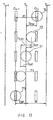
- FIG. 1 shows a configuration of a conventional magnetic recording apparatus which detects a tracking error signal by using light.
- a linearly polarized divergent beam 70 radiated from a semiconductor laser light source 10 is converted to a parallel beam by a collimator 20 and the parallel beam enters a polarizing beam splitter 30. All the parallel beam 70 entering the polarizing beam splitter 30 passes through the polarizing beam splitter 30 and enters a 1/4 wavelength plate 31.
- the parallel beam 70 is converted to a circularly polarized beam by passing through the 1/4 wavelength plate 31 and is focused on a magnetic recording medium 40 by an object lens 21.
- FIG. 2 shows the relationship between the magnetic recording medium 40 and the focused light beam 70.
- the magnetic recording medium 40 has tracks Tn-1, Tn, Tn+1 ..., which include the area on which information is recorded or reproduced by a magnetic head 99 with a certain pitch pt (approximately 20 ⁇ m). Further, discrete guiding grooves Gn-1, Gn, Gn+1 ..., which enable the optical detection of a signal synchronizing a tracking error signal and which enables rotations of the magnetic recording medium 40, are formed in the middle of adjacent tracks.
- the beam 70 reflected and diffracted by the magnetic recording medium 40 passes through the object lens 21 again, and enters the 1/4 wavelength plate 31.
- the beam 70 is converted to a linearly polarized beam having a 90° phase change of the light source 10. All the beam passing through the 1/4 wavelength plate 31 is reflected by the polarizing beam splitter 30 and enters a photodetector 50.
- the incident light beam is converted into an electric signal by the photodetector 50 and inputted to a signal processing portion 80.
- the photodetector 50 has two light sensing portions 501, 502. Signals outputted from the light sensing portions 501, 502 are converted to voltage signals by current-voltage (I-V) converting portions 851, 852 respectively, and inputted to a differential operation part 871.
- the differential operation part 871 subtracts the two voltage signals outputted from the I-V converting portions 851, 852.
- A is an amplitude and B is a DC component.
- a signal v23 outputted from the I-V converting portion 871 can be represented by the below mentioned formula (3) and outputted from a terminal 801 as the tracking error signal.
- v 23 2 ⁇ A ⁇ sin ( 2 ⁇ x / pt )
- the signal v23 can be illustrated as FIG. 3(c).
- the tracking error signal v23 outputted from the terminal 801 is inputted to a driving portion 90 to adjust relative positions of a magnetic recording medium 40 and a base 95 including a tracking error signal detection optical system 100 and a magnetic head 99 for recording and reproducing information so as to form a desired track on the magnetic recording medium 40.
- the tracking error signal detection method is known as the push pull method.
- US-A-5 287 338 discloses an error signal generating device wherein a tracking error signal is obtained by means of a push-pull method.
- a tracking error signal generator comprising a circuit for producing peak values of output signals detected from a two-divided detector by a push-pull system and a circuit for detecting a tracking error signal from the difference between such detection signals.
- a distance d between a point S1 at which the magnetic head 99 contacts a magnetic recording medium 40 and a focal point S2 of a beam 70 from the optical system needs to be at least several hundred ⁇ m to several mm. That is, the point S1 at which the magnetic head 99 contacts the magnetic recording medium 40 and the focal point S2 of the beam 70 scan different tracks on the magnetic recording medium 40.
- the distance d is adjusted so as to have the working point of the tracking servo at the midpoint S3 of the signal amplitude of the tracking error signal v23 as illustrated in FIG. 3(c) when the point S1 is on a track of the magnetic recording medium 40.
- temperature or humidity change causes expansion or contraction of the magnetic recording medium 40 and the track pitch pt changes accordingly. Therefore, in the tracking operation at the point S3 using the tracking error signal v23 obtained from the optical system 100, the point S1 becomes off track and thereby drastically deteriorates the information reproduction characteristics.
- a tracking servo can be enabled by applying an offset voltage to the tracking servo.
- the dynamic range of the orientation illustrated by the arrow D1 lowers and thereby deteriorate the followability in the case disturbance generates.
- the servo gain of the tracking operation lowers.
- the point S4 eventually reaches the point S5, a new problem occurs that the servo gain of the tracking becomes 0 thereby completely losing the tracking servo.
- Dusts or flaws on the magnetic recording medium 40 change the reflection ratio of the magnetic recording medium 40 and the intensity of a light beam 70 reflected thereby accordingly.
- a problem occurs in that an offset occurs in the tracking error signal, and thus the magnetic head 99 can not be controlled on a desired track of the magnetic recording medium 99.
- an optically optimum value for a numerical aperture NA of the object lens 21 for a magnetic recording medium having a track pitch of 50 ⁇ m is about 0.017.
- an angular dislocation ⁇ exists between the beam 70 focused by the object lens 21 and the magnetic recording medium 40, the beam 70 reflected by the magnetic recording medium 40 can not enter the aperture. Therefore a problem occurs in that the quantity of the light beam introduced to the photodetector 50 decreases and thus the tracking operation becomes unstable.
- the angular dislocation ⁇ is 0.97 when the quantity of light I of the beam 70 on the photodetector 50 is 0, namely, the performance function Ev is 1. In this case, the tracking error signal can not be obtained at all.
- An object of the present invention is to provide a magnetic recording apparatus which can detect a tracking error signal stably even when an angle dislocation ⁇ exists between the beam 70 focused by the object lens 21 and the magnetic recording medium 40, and an adjusting method thereof.
- an angle dislocation between the optical axis of the beam focused by the converging optical system and the magnetic recording medium caused by the installation error of the mirror used for reducing the area occupied by the optical system can be prevented since the movement of a mirror can be offset by the movement of another mirror.
- a magnetic recording apparatus which can stably detect a tracking error signal stablly can be provided.
- FIG. 1 is a diagram illustrating the configuration of a tracking error signal detection apparatus of a conventional magnetic recording apparatus.
- FIG. 2 is a diagram illustrating the relationship between a magnetic recording medium and a light beam in a conventional magnetic recording apparatus.
- FIG. 3 is a graph illustrating signal wave forms of a signal processing portion in a conventional magnetic recording apparatus.
- FIG. 4 is a graph illustrating a relationship between the tilt of a magnetic recording medium and a quantity of light incident on an object lens in a conventional magnetic recording apparatus.
- FIG. 5. is a diagram illustrating the configuration of a magnetic recording apparatus and a tracking error signal detection apparatus of the first embodiment of the present invention.
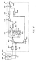
- FIG. 6 is a diagram illustrating a signal processing portion of the first embodiment.
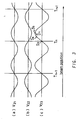
- FIG. 7 is a diagram illustrating the relationship between guiding grooves of the magnetic recording medium and timing signals in the first embodiment.
- FIG. 8 is a graph illustrating signal wave forms of the signal processing portion of the first embodiment.
- FIG. 9 is a diagram illustrating the configuration of a magnetic recording apparatus and a tracking error signal detection apparatus of the second embodiment.
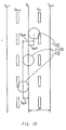
- FIG. 10 is a diagram illustrating guiding grooves of the magnetic recording medium and timing signals in the second embodiment.
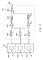
- FIG. 11 is a diagram illustrating the signal processing portion in the second embodiment.
- FIG. 12 is a diagram illustrating a magnetic recording apparatus and a signal processing portion of the tracking error signal detection apparatus of the third embodiment of the present invention.
- FIG. 13 is a diagram illustrating a magnetic recording apparatus and the relationship between guiding grooves of the magnetic recording medium and timing signals of the fourth embodiment of the present invention.
- FIG. 14 is a diagram illustrating the configuration of the signal processing portion in the fourth embodiment.
- FIG. 15 is a diagram illustrating the configuration of a magnetic recording apparatus and a tracking error signal detection apparatus of the fifth embodiment of the present invention.
- FIGs. 16A and 16B are diagrams illustrating patterns of the diffraction element in the fifth embodiment
- FIG. 16C is a diagram illustrating light beams on the photodetector and sensing portions.
- FIGs. 17A to 17C are diagrams illustrating the configuration of a lens in the fifth embodiment.
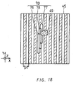
- FIG. 18 is a diagram illustrating the relationship between a reflecting body and beams in the fifth embodiment.
- FIG. 19 is a diagram illustrating the configuration of an object lens of a tracking error signal detection apparatus of the sixth embodiment of the present invention.
- FIG. 20 is a diagram illustrating the configuration of a magnetic recording apparatus and a tracking error signal detection apparatus of the seventh embodiment of the present invention.
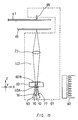
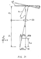
- FIG. 21 is a diagram illustrating a magnetic recording apparatus, and a relationship among a light source, an object lens, and a magnetic recording medium, and a principle of the adjusting method of a magnetic recording medium in the eighth embodiment of the present invention.
- FIG. 22 is a diagram illustrating the configuration of a light source located on an photodetector and a diffraction element in the eighth embodiment.
- FIGs. 23A, 23B are diagrams illustrating a magnetic recording apparatus and the relationship among a light source, a magnetic recording medium and an optical system in the adjusting means in the ninth embodiment of the present invention, where 23A describes the case when a reflecting plane is arranged in the correct angle, and 23B describes the case when a mirror integrally forming a reflecting plane has an angle dislocation.
- FIG. 24A is a diagram illustrating the configuration of a magnetic recording apparatus
- 24B is a diagram illustrating the configuration of a reflecting body of the tenth embodiment of the present invention.
- FIG. 25A is a plan view illustrating the configuration of a magnetic recording apparatus and an object lens of the tracking error signal detection apparatus
- FIG. 25B is a side sectional view thereof of the eleventh embodiment of the present inveniton.
- FIG. 26 is a diagram illustrating the relationship between sensing portions of an photodetector and diffracted beams of the eleventh embodiment of the present invention.
- FIG. 27 is a diagram illustrating the configuration of a magnetic recording apparatus and the tracking error signal detection apparatus in the twelfth embodiment of the present invention.
- FIG. 28A is a diagram illustrating the reflecting plane of a reflecting body
- FIG. 28B is a diagram illustrating the reflecting plane of the magnetic recording medium in the twelfth embodiment of the present invention.
- FIG. 29 is a diagram illustrating the relationship between beams on an photodetector and sensing portions in the twelfth embodiment.
- FIG. 30 is a diagram illustrating the configuration of a magnetic recording apparatus and the tracking error signal detection apparatus in the thirteenth embodiment of the present invention.
- FIGs. 31A and 31B are diagrams illustrating the area of the diffraction element in the thirteenth embodiment
- FIG. 31C is a diagram illustrating the relationship between light beams on an photodetector and sensing portions of the thirteenth embodiment of the present invention.
- FIG. 32 is a diagram illustrating the configuration of an information recording medium in the fourteenth embodiment of the present invention.
- FIG. 33 is a diagram illustrating the configuration of a signal processing portion of a tracking error signal detection apparatus in the fourteenth embodiment.
- FIG. 5 is a diagram illustrating a magnetic recording apparatus and a tracking error signal detection apparatus of the first embodiment.
- the tracking error signal detection apparatus of the magnetic recording apparatus of the first embodiment has substantially the same configuration as the prior art illustrated in FIG. 1 except the configuration of a signal processing portion 81.
- the configuration of the signal processing portion 81 of the first embodiment is illustrated in FIG. 6.
- a photodetector 50 comprises two sensing portions 501, 502. Electric signals outputted from the sensing portions 501, 502 are inputted to a signal processing portion 81 respectively. The signals outputted from the sensing portions 501, 502 are converted to voltage signals by I-V converting portions 851, 852 respectively. Two voltage signals outputted from the I-V converting portions 851, 852 are inputted to a differential operation part 872 and an addition part 891 respectively. The differential operation part 872 subtracts two voltage signals outputted from the I-V converting portions 851, 852.
- a signal v1 outputted from the differential operation part 872 becomes a sine wave represented by the below mentioned formula (4) when a light beam 70 has a displacement x from the central portion of a groove (for example, Gn in FIG. 2).
- A1 denotes an amplitude.
- v 1 A 1 ⁇ sin ( 2 ⁇ x / p t )
- a signal outputted from the differential operation part 872 is inputted to a changeable gain amplifying portions 832.
- the changeable gain amplifying portions 832 is an amplifier capable of changing an amplitude A1 of an inputted signal freely.
- a signal outputted from the changeable gain amplifying portions 832 is inputted to an operation part 892.
- the addition part 891 adds voltage signals outputted from the I-V conversion portions 851, 852.
- a signal v2 outputted from the addition part 891 becomes a sine wave represented by the below mentioned formula (5).
- A2 denotes an amplitude and B1 denotes a DC component.
- v 2 A 2 ⁇ cos ( 2 ⁇ x / p t ) + B 1
- a signal outputted from the addition part 891 is inputted to a clock signal generating portion 895 to generate clock signals CLK1, CLK2.
- the clock signal generating portion 895 is a Phase Locked Loop (PLL) circuit.
- the clock signals CLK1, CLK2 synchronize with signals obtained by scanning discrete guiding grooves Gn-1, Gn ... formed on the magnetic recording medium 40 illustrated in FIG. 2.
- FIG. 7 illustrates the relationship between the guiding groove Gn and the timing of clock signals CLK1, CLK2.
- the clock signals CLK1, CLK2 are inputted to a trigger signal generating portion 896 to generate timing signals Sa1, Sa2.
- a signal from the addition part 891 is outputted with the timing of the timing signals Sa1, Sa2 to be sampled and held by sample and hold portions 811, 812.
- a signal sampled and held by the sample and hold portion 812 is inputted to the differential operation part 873 as it is.
- a signal sampled and held by the sample and hold portion 811 is, after being adjusted to a favorable intensity by the changeable gain amplifying portions 831, inputted to the differential operation part 873.
- the gain of the changeable gain amplifying portions 831 is set to subtract the DC component B1 of the signal v2 at the differential operation part 873.
- a signal v3 outputted from the differential operation part 873 becomes a sine wave having the DC component subtracted from the signal v2 represented by the below mentioned formula (6).
- v 3 A 2 ⁇ cos ( 2 ⁇ x / pt )
- a signal outputted from the differential operation part 873 is, after being adjusted to a favorable amplitude by the changeable gain amplifying portion 833, inputted to an operation part 892.
- the operation part 892 adds an inputted signal to output a tracking error signal v4 to an output terminal 802.
- the signal v4 has a wave form represented by the below mentioned formula (7).
- K1, K2 are gains of the changeable gain amplifying portions 832, 833, respectively.
- Signals v1, v3, v4 can be illustrated as in FIGs. 8(a) to 8(c).
- a tracking error signal v4 outputted from a terminal 802 is inputted to a driving portion 90.
- the driving portion 90 adjusts the relative position of a magnetic recording medium 40 and a base 95 comprising a tracking error signal detection optical system 100 and a magnetic head 99 for recording and reproduction of information tracked to the magnetic head 99 based on the tracking error signal v4 so as to have a magnetic head 99 tracked on a desired track.
- a point S1 at which the magnetic head 99 contacts with the magnetic recording medium 40 and a converging point S2 of a beam 70 from the optical system scan different tracks on the magnetic recording medium 40 respectively.
- the track pitch pt changes accordingly.
- a point S1 can be on track at a midpoint of the amplitude of the tracking error signal.
- a gain of the tracking servo and a dynamic range become maximum as illustrated in FIG. 3(c).
- information can be recorded or reproduced on the magnetic recording medium 40 in the best condition. Accordingly, the use of the magnetic recording apparatus stabilizes the tracking operation significantly. Not only in the case of such temperature or humidity change, but also in the use of a magnetic recording apparatus using a changeable medium such as a floppy disk, tracking servo operation can be conducted at the best point. Further, a good interchangeability between different magnetic recording media can be provided.
- the gains K1, K2 of the changeable gain amplifying portions 832, 833 can be adjusted to have a signal read out from the magnetic head 99 to be the best.
- a method to adjust the gain of the changeable gain amplifying means conventional methods such as changing the bias voltage applied on a semiconductor element, such as a PIN diode, a bipolar transistor and a field effect transistor (FET) can be employed.
- a tracking error signal can be obtained with a simple optical system to focus a light beam on a magnetic recording medium in the magnetic recording apparatus of this embodiment, a magnetic recording apparatus having an inexpensive optical system can be provided.
- FIG. 9 is a diagram illustrating a magnetic recording apparatus and a tracking error signal detection apparatus of the second embodiment.
- the magnetic recording apparatus of the second embodiment has the same configuration as the first embodiment illustrated in FIG. 5 except that a diffraction grating 32 generates three beams between the light source 10 and the collimator 20, a beam 70 reflected by the polarizing beam splitter 30 is focused with a focusing lens 22, and a photodetector 51 and a signal processing portion 82 use a different configuration.
- the other components are the same as the first embodiment.
- the beam 70 focused on the magnetic recording medium 40 is illustrated in FIG. 10.
- the beam 70 comprises three beams 71 to 73.
- the beam 71 is a zeroth-order diffracted light of the diffraction grating 32
- the beams 72, 73 are first-order diffracted lights of the diffraction grating 32, respectively.
- the beams 71, 72, 73 are located so as to radiate different positions of a track. Namely, the beams 71 and 72 and the beams 71 and 73 differ by pt/4 (pt : track pitch) respectively and the beams 72 and 73 differ by pt/2.
- the configuration of an photodetector 51 and a signal processing portion 82 are illustrated in FIG. 11.
- the photodetector 51 comprises three sensing portions 503 to 505 for sensing beams 71 to 73, respectively.
- Electric signals outputted from the sensing portions 503 to 505 of the photodetector 51 are inputted to the signal processing portion 82 to be converted to voltage signals by I-V converting portions 853 to 855, respectively.
- Signals v5 to v7 outputted from the I-V converting portions 853 to 855 are inputted to the signal processing portion 82 to be converted to voltage signals.
- the signals v5 to v7 outputted from the I-V converting portions 853-855 are signals represented by the below mentioned formulae (8) to (10).
- A3 denotes an amplitude
- B2 denotes a DC component.
- v 5 A 3 ⁇ cos ( 2 ⁇ x / p t ) + B 2
- v 6 A 3 ⁇ sin ( 2 ⁇ x / p t ) + B 2
- v 7 ⁇ A 3 ⁇ sin ( 2 ⁇ x / p t ) + B 2
- Signals v5, v6 are inputted to a differential operation part 874, and signals v5, v7 are inputted to a differential operation part 875, respectively for subtraction.
- Signals v8, v9 outputted from the differential operation parts 874, 875 are signals represented by the below mentioned formulae (11) and (12).
- A4 denotes an amplitude.
- v 8 A 4 ⁇ sin ( 2 ⁇ x / p t + ⁇ / 4 )
- v 9 A 4 ⁇ sin ( 2 ⁇ x / p t ⁇ ⁇ / 4 )
- Signals v8, v9 are sine waves out of phase by ⁇ /2.
- the signals v8, v9 outputted from the differential operation parts 874, 875 are inputted to the changeable gain amplifying portions 834, 835, respectively to be adjusted to a favorable amplitude, and inputted to the operation part 893.
- the operation part 893 conducts addition of inputted signals, and outputs a tracking error signal v10 to an output terminal 803.
- the signal v10 has a wave form represented by the below mentioned formula (13).
- K3, K4 are gains of the changeable gain amplifying portions 874, 875, respectively, and ⁇ 1 is - ⁇ /4.
- a signal v10 can be a signal capable of setting optional phase and amplitude by selecting appropriate gains K3, K4. This can be easily understood in the comparison between the formula (13) and the formula (7) described in the first embodiment.
- a tracking error signal v10 outputted to a terminal 803 is inputted to a driving portion 91.
- the driving portion 91 adjusts the relative position of a magnetic recording medium 40 and a base 96 comprising a tracking error signal detection optical system 101 and a magnetic head 99 so as to have a magnetic head 99 tracked on a desired track.
- guiding grooves Gn-1, Gn ... need not have a discrete configuration.
- this embodiment can be applied also to a magnetic recording medium having a continuous guiding groove.
- FIG. 12 is a diagram illustrating the configuration of the signal processing portion 83 of the third embodiment. Since the configuration of the other parts are the same as the above mentioned second embodiment, details are not explained herein.
- the signal processing portion 83 illustrated in FIG. 12 differs from the signal processing portion 82 illustrated in FIG. 11 in that signals v5 to v7 are inputted to the differential operation parts 874, 875 via the changeable gain amplifying portions 836 to 839.
- three beams 71 to 73 are generated by the diffraction grating 32 illustrated in FIG. 9 and the beam 71 is a zeroth-order diffracted light of the diffraction grating 32, and the beams 72, 73 are first-order diffracted lights of the diffraction grating 32, respectively.
- the intensity of the first-order diffracted lights 72 and 73 can be formed identical comparatively easily even when the width, depth or shape of the lattice of the diffraction grating 32 has an irregularity in the production.
- the width, depth and shape of the lattice of the diffraction grating needs to be maintained precisely.
- the signal amplitude of inputted signals v5 to v7 can be adjusted to a favorable level. Accordingly, even if the intensities of the zeroth-order diffracted light 71 and the first-order diffracted lights 72, 73 generated at the diffraction grating 32 are different, a DC component contained in a signal outputted from the differential operation parts 874, 875 can be curbed to a sufficiently small level.
- the tracking error signals are outputted to a terminal 804.
- the third embodiment even when the width, depth or shape of the lattice of the diffraction grating 32 has an irregurality in the production of a diffraction grating 32 to generate a plurality of diffracted lights, a stable tracking servo operation can be realized. Further, when the intensity distribution of the beam 70 radiated from the light source 10 is not uniform and thus the intensities of the diffracted lights 71 to 73 become different, this can also be tolerated without causing any problem. According to the configuration of the third embodiment, requirements toward the production accuracy of the lattice of a diffraction grating and the installation accuracy of the light source can be drastically alleviated to achieve the reduction of the diffraction grating costs and the assembly costs.
- the fourth embodiment concerning a magnetic recording apparatus and the tracking error signal detection apparatus will be explained with reference to FIGs. 13 and 14.
- the configuration of the fourth embodiment is similar to the configuration of the second embodiment except for the configuration of the photodetector and the signal processing portion. Therefore, details are not explained for the common parts.
- FIG. 13 illustrates beams focused on a magnetic recording medium 40 in the fourth embodiment.
- the beam 71 is a zeroth-order diffracted light of the diffraction grating 32
- the beams 72, 73 are first-order diffracted lights of the diffraction grating 32
- the beams 74, 75 are second-order diffracted lights of the diffraction grating 32, respectively.
- the beams 71 to 75 are located so as to radiate different positions of a track, namely, the beams 71 and 72 and the beams 71 and 73 differ by pt/4 respectively, the beams 71 and 74 and the beams 71 and 75 differ by pt/2 respectively, the beams 72 and 73 differs by pt/2, and the beams 74 and 75 differs by pt.
- the configuration of a photodetector 52 and a signal processing portion 84 are illustrated in FIG. 14.
- the photodetector 52 comprises five sensing portions 506 to 510 for sensing beams 71 to 75, respectively.
- Five electric signals outputted from the sensing portions 506 to 510 are inputted to the signal processing portion 84 to be converted to voltage signals by I-V converting portions 853 to 856, respectively.
- Signals outputted from the sensing portions 509 and 510 are added at the input side of the I-V converting portion 856.
- the signals v11 to v14 outputted from the I-V converting portions 853 to 856 are signals represented by the below mentioned formulae (14) to (17).
- A5 to A7 denote an amplitude
- B3 to B5 denote a DC component.
- v 11 ⁇ A 5 ⁇ sin ( 2 ⁇ x / p t ) + B 3
- v 12 ⁇ A 6 ⁇ cos ( 2 ⁇ x / p t ) + B 4
- v 13 A 7 ⁇ sin ( 2 ⁇ x / p t ) + B 5
- v 14 A 6 ⁇ cos ( 2 ⁇ x / p t ) + B 4
- Signals v11 to v14 are inputted to changeable gain amplifying parts 836 to 839 respectively, and after being adjusted to a favorable amplitude, inputted to differential operation parts 874, 875 to conduct subtraction.
- the reason why the changeable gain amplifying portions 836 to 839 are arranged at the input side of the differential operation parts 874, 875 is the same as the reason why the changeable gain amplifying portions 836 to 839 are similarly arranged in the third embodiment.
- Signals v15, v16 outputted from the differential operation parts 874, 875 are signals represented by the below mentioned formulae (18) and (19).
- A8 and A9 denote an amplitude.
- v 15 A 8 ⁇ sin ( 2 ⁇ x / p t )
- Signals v15, v16 are sine waves out of phase by ⁇ /2.
- the signals v15, v16 outputted from the differential operation parts 874, 875 are inputted to the changeable gain amplifying portions 834, 835, respectively to be adjusted to a favorable amplitude, and inputted to the operation part 893.
- the operation part 893 conducts addition of inputted signals, and outputs a tracking error signal v17 to an output terminal 805.
- the signal v17 can be a signal capable of setting optional phase and amplitude by adjusting the gain of the changeable gain amplifying portions 834, 835.
- a magnetic recording medium 40 has a continuous spiral or concentric track to be rotated by a driving motor as represented by a floppy disk.
- the phases of signals inputted to the differential operation parts 874, 875 are different by ⁇ /2 respectively as described with the formulae (14) to (17). Accordingly, even when the rotation center of the driving motor and the rotation center of the magnetic recording medium 40 are not exactly alligned in rotating the magnetic recording medium 40 thereby causing the decentering of the track, deterioration of the tracking error signals is smaller. That is, according to the fourth embodiment, a stable tracking servo operation can be conducted even when rotations of the magnetic recording medium are greatly decentered.
- the signal processing portion can be realized through hardware by using an analog device such as an operational amplifier, however, it is also feasible to process through software after converting an analog signal to a digital signal, and thus the configuration of the signal processing portion does not cause particular limitations.
- the operation parts 432 to 434 for adding two signals out of phase by ⁇ /2 can be replaced by differential operation parts depending upon the polarity of signals.
- the operation parts can comprise a switching device to output some of the inputted signals selectively.
- the switching device to output some of the inputted signals selectively.
- FIG. 15 illustrates the configuration of a magnetic recording apparatus and the tracking error signal detection apparatus of the fifth embodiment.
- a linearly polarized divergent beam 70 radiated from a semiconductor laser light source 10 enters the area 60A of a diffraction element 60 to become three beams, that is, zeroth-order and ⁇ first-order diffraction lights.
- a plurality of beams are further generated from the three beams generated in the area 60A.
- the grating pitch of the area 60B is designed so that only the zeroth-order diffraction light out of the diffraction lights generated in the area 60B enters the aperture of the object lens 23 in the optical path extending from the light source 10 to the object lens 23.
- the object lens 23 is a finite object lens to focus the beam 70 on the reflecting body 45.
- Lattice patterns with a cycle pt of 10 ⁇ m are formed on the reflecting body 45.
- the cycle pt is identical to the cycle of the track on the magnetic recording medium 41.
- the beam reflected and diffracted by the reflecting body 45 enters the area 60B of the diffraction element 60 after passing through the objective lens 23 again.
- a plurality of diffracted lights are generated from the beam which entered the area 60B.
- ⁇ first-order diffraction lights 76, 77 are sensed by the photodetector 53 to be converted to electric signals.
- FIG. 16A illustrates a pattern of the area 60B of the diffraction element 60.
- FIG. 16B illustrates a pattern of the area 60A of the diffraction element 60.
- FIG. 16C illustrates beams 76 to 77 on the photodetector 53 and sensing portions 511 to 516 formed on the photodetector 53.
- a grating with a 10 ⁇ m cycle is formed on the area 60A of the diffraction element 60, and a grating with a 3 ⁇ m cycle is formed on the area 60B of the diffraction element 60, respectively.
- Orientation of the grating formed on the area 60A and orientation of the grating formed on the area 60B are orthogonal to each other.
- the light source 10 is arranged on the photodetector 53 comprising an etched silicon substrate.
- a light beam 70 radiated from the light source is reflected by a mirror 53A formed on the silicon substrate so that the optical path of the beam 70 becomes perpendicular to the plane in which the sensing portions 511 to 516 of the photodetector 53 are formed.
- Beams 76A, 77A are zeroth-order diffraction beams generated by the incidence to the area 60A of the diffraction element 60 of the beam 70 radiated from the light source
- beams 76B, 76C, 77B and 77C are ⁇ first-order diffraction beams generated by the incidence to the area 60A of the diffraction element 60 of the beam 70.
- the beams 76A to 76C and the beams 77A to 77C are sensed at the sensing portions 511 to 516, respectively.
- a tracking error signal can be generated. Specifically, this can be achieved by inputting signals outputted from the sensing portions 511 and 514 into the I-V converting portion 854, signals outputted from the sensing portions 512 and 515 into the I-V converting portion 853, and signals outputted from the sensing portions 513 and 516 into the I-V converting portion 855, respectively.
- a tracking error signal v10 outputted on the terminal 803 of the signal processing portion 82 of FIG. 11 is inputted to the driving portion 92.
- the driving portion 92 adjust the relative position between the magnetic recording medium 41 and the base 97 including the tracking error signal detection optical system 102 and the magnetic head 99 for tracking the magnetic head 99 at a desired track.
- FIGs. 17A to 17C illustrates the relationship between the aperture size and the focal length of the object lens 23.
- Wx, Wy denote the aperture size of the object lens 23 to the X axis orientation and to the Y axis orientation, respectively.
- fx, fy denote the length between the reflecting body 45 side of the object lens 23 and the focal point of the beam to the X axis orientation and to the Y axis orientation, respectively.
- Wx Wy 2mm
- fx 12 mm
- fy ⁇ , that is, the object lens 23 has the same aperture size in the X axis orientation and in the Y axis orientation, and different focal lengths in the X axis orientation and in the Y axis orientation.
- This lens is a kind of a cylindrical lens.
- X, Y, Z axes orientations correspond with the X, Y, Z axes orientations described in FIG. 15, That is, X axis orientation is the orientation orthogonal to the track, Y axis orientation is the orientation parallel to the track, and Z axis orientation is the orientation orthogonal to the X and Y axes orientations.
- FIG. 18 illustrates the relationship between the reflecting body 45 and the beam focused by the object lens 23.
- the beam 70 comprises three beams 76 to 78, which are zero-order and first-order diffraction lights generated by the incidence of the beam 70 radiated from the light source 10 into the area 60A of the diffraction element 60.
- the beam 70 focused on the reflecting body 45 becomes strip-like having the X axis orientation size of about 5 ⁇ m and the Y axis orientation size of about 2 mm.
- the partial reflecting ratio change can be averaged to reduce the intensity variation of the three beams 76 to 78. Accordingly, the offset generated in a tracking error signal becomes small.
- the respective length between the center of the beams 76 to 78 are set to be about 100 ⁇ m, most of the area of the beams overlap to each other. Therefore, even when a partial reflection ratio change occurs in the reflecting body 45, the change is corrected by the three beams 76 to 78 and thus the intensity variance of the three beams 76 to 78 reflected by the reflecting body 45 becomes small. If the intensity of the three beams 76 to 78 is varied, an offset occurs in the tracking error signal to cause an off track. On the other hand, when the intensity of the three beams 76 to 78 change but are not varied, although the servo gain decreases, an offset does not occur and thus the magnetic head can be controlled on a desired track.
- FIG. 19 illustrates the configuration of an object lens 24 of the sixth embodiment.
- the object lens 24 is used in the sixth embodiment in place of the object lens 23 in the fifth embodiment. Since other configurations are the same, details are not explained herein.
- the Y axis orientation aperture Wy of the object lens 24 is larger than the X axis orientation aperture Wx.
- Wx 2 mm
- Wy 5mm.
- the relationship between the track pitch pt of the reflecting body 45 and the aperture of the object lens needs to be maintained in a certain range.
- the Y axis orientation it can be optionally set as long as signals from guiding grooves can be detected.
- the size of the beam 70 on the reflecting body 45 when the object lens 24 is used can further be larger in the Y axis orientation compared with the case of using the object lens 23, namely, 5 ⁇ m in the X axis orientation and 5 mm in the Y axis orientation.
- the sixth embodiment by having a larger aperture of the object lens 24 in the Y axis orientation, influence of the angle dislocation between the reflecting body 45 and the beam 70 can be tolerated in the Y axis orientation without adjustment. Therefore, in the assembly of a magnetic recording apparatus using a tracking error signal detection apparatus of the sixth embodiment, angle dislocation needs to be adjusted only to the X axis orientation, and thus the adjustment operation can be conducted in a shorter time period. Accordingly, the magnetic recording apparatus of the sixth embodiment enables easy production at a lower cost.
- a tracking error signal can be obtained even when guiding grooves for enabling the detection of a tracking error signal are not formed on the magnetic recording medium.
- the tracking operation can be conducted on a magnetic recording medium having a track pitch of 188 ⁇ m called 2HD, which is widely used.
- FIG. 20 illustrates the configuration of a magnetic recording apparatus and the tracking error signal detection apparatus of the seventh embodiment.
- the configuration of the magnetic recording apparatus and the tracking error signal detection method of the seventh embodiment are the same as in the fifth embodiment except that guiding grooves for enabling the optical detection of a tracking error signal are formed on a magnetic recording medium 42 in the seventh embodiment.
- the magnetic recording medium 42 is equivalent to the compound of the magnetic recording medium 41 and the reflecting body 45 illustrated in FIG. 15.
- the optical system to detect tracking error signals and the magnetic head 99 are installed on a base 98. Tracking operation is conducted by inputting a tracking error signal into a driving portion 93.
- FIG. 21 illustrates the relationship among the light source 10, the object lens 23 and the magnetic recording medium 42.
- the configuration of the optical system to detect the tracking error signals is the same as the configuration of the seventh embodiment illustrated in FIG. 20.
- the angle dislocation of the magnetic recording medium 42 is not adjusted, but is compensated by adjusting the position of the light source 10 to the X axis orientation and to the Y axis orientation, which are orthogonal to the optical axis of the object lens 23.
- Z1 is the length from the light source 10 to the object lens 23
- the vignetting in the object lens 23 caused by the angle dislocation ⁇ in fixing the magnetic recording medium 42 can be completely compensated.
- a diffraction element 60 is used as the beam splitting means to guide a beam 70 reflected by the magnetic recording medium 42, by forming the light source 10 and the diffraction element 60 integrally, a tracking error signal can be detected with further stability.
- Z1 20 mm
- Z2 15 mm
- ZLH 3 mm
- NA 0.017
- RLH 38 ⁇ m.
- the ⁇ first-order diffraction lights generated by the area 60B on the way from the light source 10 toward the object lens 23 enter the aperture of the object lens 23 to become a noise with respect to a tracking error signal. It is possible to avoid the incidence of the ⁇ first-order diffraction lights from the area 60B to the aperture of the object lens 23 by shortening the pitch of the grating pattern of the area 60B. In this case, however, the area of the photodetector 53 needs to be enlarged, and thus the magnetic recording apparatus becomes expensive.
- the size of the area 60B can be further smaller by forming the light source 10 and the diffraction element 60 integrally to prevent the incidence of the ⁇ first-order diffraction lights generated in the area 60B into the object lens, and thus a greater angle dislocation ⁇ of the magnetic recording medium 42 can be tolerated to a greater angle.
- FIG. 22 illustrates the configuration where a light source 10 and a diffraction element 60 are formed integrally on a photodetector 53.
- the photodetector 53 is arranged at the bottom of a package 33 and the diffraction element 60 having a form of a case to protect the photodetector 53 is arranged on the package.
- the package 33 and the diffraction element 60 is firmly bonded with an adherent.
- the position adjustment of the light source to the X axis orientation and the Y axis orientation is conducted by moving the package 33 to the X axis orientation and the Y axis orientation. In this case, since the diffraction element 60 is bonded and fixed to the package 33, the diffraction element 60 moves according to the movement of the package 33.
- FIGs. 23A and 23B illustrate the relationship between the light source 10 and the magnetic recording medium 42, respectively.
- the basic configuration of the magnetic recording apparatus of the ninth embodiment is the same as the configuration of the seventh embodiment illustrated in FIG. 20 except that the ninth embodiment has two reflecting planes 34A, 34B for deflecting the optical path in the front and back of the object lens 23 so as to reduce the bulk of the optical system.
- respective angle displacements of the reflecting planes 34A and 34B may prevent the incidence of a light beam reflected by the magnetic recording medium 42 into the aperture of the object lens 23.
- angle displacements of the reflecting planes 34A and 34B exist to a degree which cannot be neglected.
- FIG. 23B illustrates the case when a mirror 34 having the reflecting planes 34A and 34B integrally formed has an angle displacement ⁇ M.
- a mirror 34 include a plastic block molded to have a triangle section with the reflecting planes 34A, 34B formed by plating the surface with a metal.
- the relative angle accuracy between the reflecting planes 34A, 34B depends on the accuracy of the mold used for forming the mirror 34. Therefore, by using a mold with a high accuracy, mass production of a mirror 34 with little relative angle displacement between two reflecting planes 34A, 34B can be achieved.
- the angle displacement of the reflecting plane 34A can be compensated by the angle displacement of the reflecting plane 34B, and thus the angle formed by the magnetic recording medium 42 and the light beam is always constant without dependency on the angle displacement ⁇ M caused in the installation of the mirror. Accordingly, the light beam reflected by the magnetic recording medium 42 enters the aperture of the object lens 23. As a consequence, according to this embodiment, downsizing and easy assembly of the magnetic recording apparatus can be realized.
- the range of the allowance of the installation angle error of the mirror 34 will be wider to further facilitate the assembly.
- FIGs. 24A and 24B illustrate the configuration of a magnetic recording medium 43 and a reflecting body 46.
- the basic configuration of the optical system of the magnetic recording apparatus of the tenth embodiment is the same as the configuration of the fifth embodiment illustrated in FIG. 15 except that the tenth embodiment has a magnetic recording medium 43 and a reflecting body 46 instead of a magnetic recording medium 41 and a reflecting body 45 indicated in FIG. 15.
- the pitch of guiding grooves of the reflecting body 46 is pt/2 whereas the track pitch on the magnetic recording medium 43 is pt.
- the numerical aperture NA of the object lens 23 can be larger in inverse proportion to the pitch of guiding grooves.
- the optimum value of the numerical aperture NA of the object lens 23 in the fifth embodiment is 0.017. Accordingly, since the guiding groove pitch is pt/2, the optimum value of the numerical aperture NA of the object lens 23 when the reflecting body 46 of the tenth embodiment is used becomes 0.034.
- the angle displacement caused by fixing the reflecting body 46 in assembling the magnetic recording apparatus may prevent the incidence of the light beam reflected by the reflecting body 46 into the aperture of the object lens 23.
- the numerical aperture of the object lens 23 can be optionally set by changing the pitch of guiding grooves on the reflecting body 46, effect of the angle displacement caused by fixing the reflecting body 46 can be avoided by enlarging the numerical aperture NA of the object lens 23. That is, a magnetic recording apparatus without the need of the adjustment in assembling can be provided at a low cost.
- FIG. 25A is a plan view illustrating the configuration of an object lens 25 of the magnetic recording apparatus and the tracking error signal detection apparatus of the eleventh embodiment.
- FIG. 25B is a cross sectional view of thereof.
- FIG. 26 illustrates the relationship between the photodetector 54 and the light beams 78, 79.
- the basic configuration of the optical system of the magnetic recording apparatus and the tracking error signal detection apparatus of the eleventh embodiment is the same as the configuration of the fifth embodiment illustrated in FIG. 15 except that the eleventh embodiment has the object lens 25 and the photodetector 54 instead of the object lens 23 and the photodetector 53 of the fifth embodiment.
- the object lens 25 comprises a simple lens as the area 25A and a lens having a diffraction grating formed thereon as the area 25B.
- the numerical aperture NA of the area 25A is 0.017 and the numerical aperture of the area 25B is 0.034.
- the diffraction grating of the area 25B has a sawtooth-like sectional form to prevent the generation of unnecessary diffraction lights as a noise in a tracking error signal.
- the depth of the grating is designed so that a zeroth-order diffraction light generated by the area 25B becomes 0.
- the apparatus is designed so that the numerical aperture of the area 25B does not become unnecessarily large with respect to the light beam 70 focused on the reflecting body.
- the light beam reflected by the reflecting body 45 returns to the area 25A.
- the light beam reflected by the reflecting body 45 according to the displaced angle enters the area 25B.
- the light beam entering the area 25B becomes a +first-order diffraction light and enters the area 60B of the diffraction element 60.
- a photodetector 54 comprises three sensing portions 517 to 519 for sensing diffraction lights 78, 79 from the area 60B of the diffraction element 60.
- the beam 78 is a diffraction light generated by a beam passing through the area 25A of the object lens
- the beam 79 is a diffraction light generated by a beam passing through the area 25B of the object lens.
- the beams 78, 79 comprise three beams 78A to 78C, and 79A to 79C, respectively. These are zero-order diffraction lights and ⁇ first-order diffraction lights generated in the area 60A of the diffraction element 60 in the optical path extending from the light source 10 to the reflecting body 45.
- the light source 10 On the photodetector 54 is the light source 10.
- the light beam 70 radiated from the light source 10 is reflected by the mirror 54A and deflected to the orientation perpendicular to the plane including the sensing portions 517 to 519 of the photodetector.
- the eleventh embodiment even when a light beam reflected by the reflecting body 45 cannot enter the aperture of the area 25A of the object lens 25 due to the angle displacement caused in fixing the reflecting body 45, the light beam can be guided to the photodetector 54 after entering the area 25B and being diffracted. Therefore, vignetting of a beam at the object lens 25 does not occur at all. Accordingly, The effect of the angle displacement caused in fixing the reflecting body 45 can be avoided. That is, a magnetic recording apparatus without the need of the adjustment in assembling can be provided at a low cost.
- FIG. 27 illustrates the configuration of a magnetic recording apparatus and the tracking error signal detection apparatus of the twelfth embodiment.
- the linearly polarized divergent beam 70 radiated from the semiconductor laser light source 10 enters the diffraction grating 32.
- the incident light is diffracted by the diffraction grating 32 to become three beams.
- the three beams generated by the diffraction grating 32 enter the polarizing beam splitter 35.
- a light beam entered the area 35A of the polarizing beam splitter 35 is further splitted to two beams 70A, 70B.
- the beam 70A is a light beam reflected by the area 35A
- the beam 70B is a light beam reflected by the area 35B after passing through the area 35A.
- the beams 70A, 70B are converted to circularly polarizated beams by passing through the 1/4 wavelength plate 36 and collected by the areas 26A, 26B of the object lens 26, respectively.
- the collected beams 70A, 70B are reflected by the mirrors 37, 38, respectively to deflect the optical path and are focused on the magnetic recording medium 44 and the reflecting body 47.
- the mirrors 37, 38 By the use of the mirrors 37, 38, the beams 70A, 70B can be guided onto the magnetic recording medium 44 and the reflecting body 47 respectively by deflecting the optical path.
- FIG. 28A illustrates the reflecting plane of the reflecting body 47
- FIG. 28B illustrates the reflecting plane of the magnetic recording medium 44
- a grating pattern 7AR having a pitch pt1 of 188 ⁇ m is formed on the reflecting plane of the reflecting body 47.
- a grating pattern 7BR having a pitch pt2 of 50 ⁇ m is formed on the reflecting plane of the magnetic recording medium 44.
- a track pitch of the grating pattern having a pitch of 188 ⁇ m is the same as the track pitch of broadly used floppy disks having a diameter of 3.5 inches or 5 inches called 2DD or 2HD, and thus the grating patterns 7AR, 7BR provide tracks.
- the reflecting body 47 comprises a glass substrate and the grating pattern 7AR is formed by depositing a metal such as aluminum and chromium thereon.
- the magnetic recording medium 44 comprises a polyester substrate applied with a magnetic substance and the grating pattern 7BR on the magnetic recording medium 44 is formed by pressing.
- the beams 70A, 70B radiated to the magnetic recording medium 44 and the reflecting body 47 each comprise three beams 70AA to 70AC, 70BA to 70BC respectively generated by the diffraction grating 32.
- the beams 70BA to 70BC radiate areas different from each other by pt1/4 with respect to the pitch pt1. Further, beams 70AA to 70AC radiate areas different from each other by pt2/4 with respect to the pitch pt2.
- the beams 70A, 70B reflected and deflected by the magnetic recording medium 44 and the reflecting body 47 are converted to linearly polarized beams having the polarization orientation forming a 90° angle compared to the polarization orientation when radiated from the light source 10 by passing through the object lens 26 again and a 1/4 wavelength plate 36.
- the beams 70A, 70B after passing through the 1/4 wavelength plate 36 pass through the polarizing beam splitter 35 and enter the converging lens 27.
- the beams 70A, 70B are converged by the areas 27A, 27B of the converging lens 27 and sensed by the photodetector 55 to be converted to electric signals.
- FIG. 29 illustrated the beams 70AA to 70AC, 70BA to 70BC on the photodetector 55 and the sensing portions 520 to 525 formed on the photodetector 55.
- the beam 70AA is sensed by the sensing portion 524.
- the beam 70AB is sensed by the sensing portion 523, the beam 70AC by the sensing portion 525, the beam BA by the sensing portion 521, the beam 70BB by the sensing portion 520, and the beam 70BC by the sensing portion 522, respectively.
- Electric signals outputted from the photodetector 55 are inputted to the signal processing portion.
- Examples of a signal processing portion include a signal processing portion 83 of the third embodiment illustrated in FIG. 12. Signals outputted from the sensing portions 520 to 522, and 523 to 525 are similar to the signals outputted from the sensing portions 503 to 505 of the second embodiment illustrated in FIG. 11, and any preferred one of the signals outputted from the sensing portions 520 to 522 or from the sensing portions 523 to 525 can be inputted to the signal processing portion according to the magnetic recording medium.
- Tracking error signals outputted from the signal processing portion are inputted to the driving portion 94.
- the driving portion 94 adjusts the relative position between the magnetic recording media 44, 48 and the base 89 including the tracking error signal detection optical system and the magnetic heads 99, 100 for tracking the magnetic heads 99, 100 on the desired tracks. Since tracking error signals are detected optically in the twelfth embodiment, an accurate tracking is enabled even when an inexpensive DC motor is used in the driving portion.
- signals outputted from the sensing portions 70BA to 70BC are used for tracking operation for the magnetic recording medium 48 having a track pitch of 188 ⁇ m and signals outputted from the sensing portions 70AA to 70AC for tracking operation for the magnetic recording medium 44 having a track pitch of 50 ⁇ m, recording and reproduction of information can be enabled in a plural kinds of magnetic recording media having different track pitches.
- the pitches of the grating patterns to be formed on a magnetic recording medium 44 and a reflecting body 47 illustrated in FIGs. 28A and 28B are examples thereof, and a magnetic recording apparatus of the twelfth embodiment can be applied to an optional track pitch by designing the optical system properly.
- the mirrors 37, 38 are used in the twelfth embodiment to deflect the optical path of the beams 70A, 70B, the same effect can be realized with other optical elements such as a prism and a diffraction grating.
- a half mirror can be used in place of the polarizing beam splitter 35. In this case, the 1/4 wavelength plate 36 becomes unnecessary, and thus an inexpensive magnetic recording apparatus can be provided.
- FIG. 27 illustrates the configuration of a magnetic recording apparatus and the tracking error signal detection apparatus of the thirteenth embodiment.
- the linearly polarized divergent beam 70 radiated from the semiconductor laser light source 10 enters the area 61A of the diffraction element 61 to become three beams, which are zeroth-order diffraction light and ⁇ first-order diffraction lights.
- the three beams generated at the area 61A further generate a plurality at the areas 61BA and 61BB.
- the grating pitch of the areas 61BA, 61BB is designed so that only the zeroth-order diffraction light among the diffracted lights generated at the areas 61BA and 61BB enters the aperture of the lens 28 in the optical path extending from the light source 10 to the object lens 28.
- the lens 28 is a finite object lens for entering different portions of the beam 70 into the areas 28A, 28B to have two kinds of beams 70C, 70D.
- the object lens 28 can be formed, for example, by molding a plastic.
- the beams 70C, 70D After being reflected by the areas 39A, 39B of the mirror 39, the beams 70C, 70D are focused on the reflecting body 47 and the magnetic recording medium 44. Like the twelfth embodiment, a grating pattern 7AR having a pitch pt1 of 188 ⁇ m is formed on the reflecting body 47. When the magnetic recording medium 44 has a track pitch narrower than 188 ⁇ m, a pattern corresponding to the track pitch is formed on the magnetic recording medium 44.
- the beams 70C, 70D reflected and diffracted by the reflecting body 47 and the magnetic recording medium 44 pass through the object lens 28 again and enter the areas 61BA, 61BB of the diffraction element 61, respectively.
- the beams entering the areas 61BA, 61BB generate a plurality of diffraction lights, and the ⁇ first-order diffraction lights are sensed by the photodetector 56.
- FIG. 31(a) illustrates the area 61BA, 61BB of the diffraction element 61.
- FIG. 31(b) illustrates the area 61A of the diffraction element 61.
- FIG. 31(c) illustrates the beams 70CA to 70CF, 70DA to 70DF on the photodetector 56 and the sensing portions 526 to 537 formed on the photodetector 56.
- the beams 70CA, 70CB, 70CC are +first-order diffraction lights generated by the incidence of the beam 70C into the area 16BA.
- the beams 70CD, 70CE, 70CF are -first-order diffraction lights generated by the incidence of the beam 70C into the area 16BA.
- the beams 70DA, 70DB, 70DC are +first-order diffraction lights generated by the incidence of the beam 70D into the area 16BB.
- the beams 70DD, 70DE, 70DF are -first-order diffraction lights generated by the incidence of the beam 70D into the area 16BB.
- the beam 70CA is sensed by the sensing portion 527.
- the beam 70CB is sensed by the sensing portion 526, the beam 70CC by the sensing portion 528, the beam 70CD by the sensing portion 536, the beam 70CE by the sensing portion 535, the beam 70CF by the sensing portion 537, the beam 70DA by the sensing portion 530, the beam 70DB by the sensing portion 529, the beam 70DC by the sensing portion 531, the beam 70DD by the sensing portion 533, the beam 70DE by the sensing portion 532, and the beam 70DF by the sensing portion 534, respectively.
- Signals outputted from the sensing portions 527 and 536, 526 and 535, 528 and 537, 530 and 533, 529 and 532, 531 and 534, combined respectively, are similar to the signals outputted from the sensing portions 520 to 525 in the first embodiment, and tracking error signals can be obtained by inputting these signals into, for example, a signal processing portion 83 of the third embodiment illustrated in FIG. 12.
- the tracking error signals generated are supplied to the driving portion 101 so as to place the magnetic heads 99, 100 on a favorable track.
- the light source 10 is arranged on the photodetector 56 comprising an etched silicon substrate.
- a light beam 70 is radiated from the light source 10 so that the optical path thereof after being reflected by a mirror 56A will be perpendicular to the plane in which the sensing portions 526 to 537 of the photodetector 56 are formed on the silicon substrate.
- the apparatus is designed so that the beams 70C, 70D reflected by the reflecting body 47 and the magnetic recording medium 44 are sensed by the photodetector 56 on which the light source is arranged. Since the finite object lens 28 is used, a downsizing of the magnetic recording apparatus can be realized. Further, since the lengths from the light source 10 to the area 28A and the light source 10 to the area 28B are the same, the lens 28 can be formed with one part, which can be formed by one molding to have the areas 28A, 28B. Accordingly, a magnetic recording apparatus can be provided at a low cost.
- the magnetic recording apparatus of the thirteenth embodiment can be used without any limitation from the detection method of the focus error signal, and thus methods generally used in the optical disk apparatus, such as the astigmatism method, the Foucault method, and the spot size detection method can be used.
- methods generally used in the optical disk apparatus such as the astigmatism method, the Foucault method, and the spot size detection method can be used.
- the example of a semiconductor laser for the light source is explained herein, other kinds of light sources such as an inexpensive light emitting diode can be used depending upon the track pitch and the numerical aperture of the lens.
- FIG. 32 illustrates the configuration of an information recording medium of the fourteenth embodiment.
- the information recording medium of the fourteenth embodiment relates to an optical disk whereas the above mentioned first to thirteenth embodiments mainly relate to magnetic recording media and magnetic recording apparatus. That is, tracking error signal detection apparatus of the present invention can be applied not only in magnetic recording media such as floppy disks but also in optical disks. Further, as the optical system of the information recording apparatus and the tracking error detection apparatus of the fourteenth embodiment, for example, the optical system of the first embodiment illustrated in FIG. 5 can be employed.
- Gn-1, Gn, Gn+1, ... denote guiding grooves as the pattern for enabling the detection of tracking error signals.
- pt denotes a pitch of an adjacent guiding groove.
- Tn-1, Tn, Tn+1, ... denote tracks by which recording and reproduction of information are conducted.
- the guiding grooves Gn-1, Gn, Gn+1, ... have cyclical two patterns R1, R2.
- the patterns R1, R2 are formed in a position different by ⁇ ⁇ pt to the orientation perpendicular to the track, respectively.
- pt 1.48 ⁇ m
- tp 0.74 ⁇ m
- ⁇ pt 0.04 ⁇ m.
- FIG. 33 illustrates the configuration of a signal processing portion 85 in an information recording apparatus and the tracking error signal detection apparatus of the fourteenth embodiment.
- Signals outputted from the sensing portions 501, 502 of the photodetector 50 are converted to voltage signals by the I-V converting portions 851, 852, respectively.
- Signals outputted from the I-V converting portions 851, 852 are subtracted by the differential operation part 872.
- Signals outputted from the differential operation part 872 are inputted to the clock signal generating portion 897 to generate clock signals CLK for synchronizing the cycles of the patterns R1, R2.
- the clock signal generating portion 897 is a Phase Locked Loop (PLL) circuit.
- the clock signals CLK are inputted to the trigger signal generating portion 898 to generate timing signals Sa3, Sa4.
- PLL Phase Locked Loop
- Signals outputted from the differential operation part 872 are sampled and held by the sample and hold portions 811, 812 with the timing of the timing signals Sa3, Sa4, respectively.
- Signals v18, v19 outputted from the sample and hold portions 811, 182 are signals represented by the below mentioned formulae (20) and (21).
- A10 denotes an amplitude.
- v 18 A 10 ⁇ sin ( 2 ⁇ ( x ⁇ ⁇ p t ) / p t )
- v 19 A 10 ⁇ sin ( 2 ⁇ ( x + ⁇ p t ) / p t )
- Signals sampled and held by the sample and hold portions 811, 812 are, after being adjusted to a preferable intensity by the changeable gain amplifying portions 832, 833, inputted to the operation part 892.
- the operation part 892 adds the inputted signals and outputs tracking error signals v20 to the output terminal 806.
- the signals v20 have a wave form represented by the below mentioned formula (22).
- v 20 K 1 ⁇ A 10 ⁇ sin ( 2 ⁇ ( x ⁇ ⁇ p t ) / p t ) + K 2 ⁇ A 10 ⁇ sin ( 2 ⁇ ( x + ⁇ p t ) / p t )
- K1, K2 are gains of the changeable gain amplifying parts 832, 833, respectively.
- Optional phase and amplitude can be set for a signal v20 by selecting appropriate gains K1, K2 as in the first embodiment.
- K1, K2 need to be changed drastically, and thus it is not practical.
- Tracking error signal detection apparatus of the fourteenth embodiment are suitable for optical disk apparatus having a phase dislocation of tracking error signals smaller than pt/2.
- a tracking error signal detection apparatus of the fourteenth embodiment Since a tracking error signal detection apparatus of the fourteenth embodiment obtains a plurality of signals having different phases from a light beam, it is barely affected even when the information recording medium has a decentering. Accordingly, information recording apparatus using a tracking error signal detection apparatus of the fourteenth embodiment have a high reliability in recording and reproducing on an information recording medium having a decentering.
Landscapes
- Optical Recording Or Reproduction (AREA)
- Moving Of The Head To Find And Align With The Track (AREA)
Claims (2)
- Appareil d'enregistrement magnétique comprenant une source de lumière (10) pour faire rayonner un rayon lumineux, un système optique convergent (23) pour faire converger le rayon lumineux rayonné depuis la source de lumière (10) sur un corps réfléchissant (42) en un point minuscule, un moyen de séparation de faisceau (60,60B) pour séparer le faisceau lumineux réfléchi et diffracté par le corps réfléchissant (42), un photodétecteur (53) pour détecter le faisceau séparé par le moyen de séparation de faisceau (60, 60B) et pour délivrer en sortie un signal en conformité avec la quantité de lumière, une tête magnétique (99) pour enregistrer des informations sur le support d'enregistrement d'informations (42) ou pour reproduire des informations à partir du support d'enregistrement d'informations (42), une partie de traitement de signal (83) pour générer un signal d'erreur de suivi à partir d'une pluralité de signaux délivrés en sortie par le photodétecteur (53), et un moyen de commande (92) pour commander le suivi de la tête magnétique par rapport au support d'enregistrement d'informations selon le signal d'erreur de suivi, dans lequel un changement physique cyclique est formé sur le corps réfléchissant (42) qui modifie le taux de réflexion, et deux miroirs (34A, 34B) qui sont supportés intégralement par un corps de soutien commun (34), sont compris pour modifier l'orientation du faisceau lumineux sur le chemin optique s'étendant depuis la source lumineuse (10) jusqu'au corps réfléchissant (42), dans lequel le système optique convergent (23) est disposé entre l'un des deux miroirs (34A, 34B) et le corps réfléchissant (42) et dans lequel l'orientation du faisceau lumineux pénétrant le corps de support commun (34) demeure essentiellement le même après être passé par le corps de support commun (34).
- Appareil d'enregistrement magnétique selon la revendication 1, dans lequel le système optique convergent (23) est disposé entre les deux miroirs (34A, 34B).
Applications Claiming Priority (9)
| Application Number | Priority Date | Filing Date | Title |
|---|---|---|---|
| JP17312395 | 1995-07-10 | ||
| JP17312395 | 1995-07-10 | ||
| JP24478495 | 1995-09-22 | ||
| JP24478495 | 1995-09-22 | ||
| JP24620995 | 1995-09-25 | ||
| JP24620995 | 1995-09-25 | ||
| JP25761695 | 1995-10-04 | ||
| JP25761695 | 1995-10-04 | ||
| EP96111030A EP0753851B1 (fr) | 1995-07-10 | 1996-07-09 | Support d'enregistrement et appareil pour détecter le défaut d'alignement et appareil d'enregistrement magnétique et méthode de centrage de la tête sur piste |
Related Parent Applications (1)
| Application Number | Title | Priority Date | Filing Date |
|---|---|---|---|
| EP96111030A Division EP0753851B1 (fr) | 1995-07-10 | 1996-07-09 | Support d'enregistrement et appareil pour détecter le défaut d'alignement et appareil d'enregistrement magnétique et méthode de centrage de la tête sur piste |
Publications (4)
| Publication Number | Publication Date |
|---|---|
| EP1329889A2 EP1329889A2 (fr) | 2003-07-23 |
| EP1329889A3 EP1329889A3 (fr) | 2004-01-21 |
| EP1329889B1 true EP1329889B1 (fr) | 2006-09-13 |
| EP1329889B8 EP1329889B8 (fr) | 2007-02-21 |
Family
ID=27474489
Family Applications (3)
| Application Number | Title | Priority Date | Filing Date |
|---|---|---|---|
| EP03006707A Expired - Lifetime EP1329889B8 (fr) | 1995-07-10 | 1996-07-09 | Appareil d'enregistrement magnétique et méthode de réglage de l'appareil d'enregistrement magnétique |
| EP03006706A Expired - Lifetime EP1327985B1 (fr) | 1995-07-10 | 1996-07-09 | Appareil de détection d'erreur de suivi de piste et appareil d'enregistrement magnétique |
| EP96111030A Expired - Lifetime EP0753851B1 (fr) | 1995-07-10 | 1996-07-09 | Support d'enregistrement et appareil pour détecter le défaut d'alignement et appareil d'enregistrement magnétique et méthode de centrage de la tête sur piste |
Family Applications After (2)
| Application Number | Title | Priority Date | Filing Date |
|---|---|---|---|
| EP03006706A Expired - Lifetime EP1327985B1 (fr) | 1995-07-10 | 1996-07-09 | Appareil de détection d'erreur de suivi de piste et appareil d'enregistrement magnétique |
| EP96111030A Expired - Lifetime EP0753851B1 (fr) | 1995-07-10 | 1996-07-09 | Support d'enregistrement et appareil pour détecter le défaut d'alignement et appareil d'enregistrement magnétique et méthode de centrage de la tête sur piste |
Country Status (5)
| Country | Link |
|---|---|
| US (1) | US5892741A (fr) |
| EP (3) | EP1329889B8 (fr) |
| KR (1) | KR100235912B1 (fr) |
| CN (5) | CN1288633C (fr) |
| DE (3) | DE69636555T2 (fr) |
Families Citing this family (15)
| Publication number | Priority date | Publication date | Assignee | Title |
|---|---|---|---|---|
| US6198711B1 (en) * | 1996-12-24 | 2001-03-06 | Sony Corporation | Equalizer for optical reproducing apparatus, using partial response method |
| DE19748324C2 (de) * | 1997-10-31 | 1999-08-26 | Siemens Ag | Optoelektronisches Sensormodul |
| US6181491B1 (en) * | 1998-08-05 | 2001-01-30 | Matsushita Electric Industrial Co., Ltd. | Optical head device, information recording and reproducing apparatus and optical system |
| JP3307347B2 (ja) * | 1998-12-02 | 2002-07-24 | 松下電器産業株式会社 | 磁気記録装置及び光学素子 |
| US6154426A (en) * | 1998-12-08 | 2000-11-28 | Matsushita Electric Industrial Co., Ltd. | Optical pick-up head unit and information record and playback equipment using the optical pick-up head unit |
| US6810002B1 (en) | 1999-01-12 | 2004-10-26 | Matsushita Electric Industrial Co., Ltd. | Information storing medium with guide tracks and information tracks |
| KR100428332B1 (ko) * | 2000-03-02 | 2004-04-28 | 마츠시타 덴끼 산교 가부시키가이샤 | 자기 기록 장치 |
| JP2002216372A (ja) * | 2001-01-23 | 2002-08-02 | Pioneer Electronic Corp | 光ピックアップ装置 |
| US7522480B2 (en) | 2001-01-25 | 2009-04-21 | Dphi Acquisitions, Inc. | Digital tracking servo system with multi-track seek with an acceleration clamp |
| KR20040029716A (ko) * | 2002-10-02 | 2004-04-08 | 삼성전자주식회사 | 디스크 구동기의 트랙킹 제어 방법 및 장치 |
| JP2005166080A (ja) * | 2003-11-28 | 2005-06-23 | Matsushita Electric Ind Co Ltd | 光ディスク装置 |
| ATE395694T1 (de) * | 2004-12-20 | 2008-05-15 | Koninkl Philips Electronics Nv | Vielpunktdetektoranordnung für mehrschichtige aufzeichnungsträger |
| US7852731B2 (en) * | 2005-03-01 | 2010-12-14 | Panasonic Corporation | Optical storage medium and optical information apparatus |
| JP2012248243A (ja) * | 2011-05-26 | 2012-12-13 | Hitachi Media Electoronics Co Ltd | 光学的情報処理装置、及び光学的情報処理装置のトラッキング制御方法 |
| CN112212789B (zh) * | 2019-07-12 | 2021-12-21 | 上海沃尔沃汽车研发有限公司 | 位置检测系统和位置检测方法 |
Citations (2)
| Publication number | Priority date | Publication date | Assignee | Title |
|---|---|---|---|---|
| US5488592A (en) * | 1993-11-11 | 1996-01-30 | Daewoo Electronics Co., Ltd. | Optical pickup device for magneto-optical disc reproducing system |
| US5537384A (en) * | 1994-06-30 | 1996-07-16 | Samsung Electronics Co., Ltd. | Focus error detector |
Family Cites Families (9)
| Publication number | Priority date | Publication date | Assignee | Title |
|---|---|---|---|---|
| US4446448A (en) * | 1982-08-13 | 1984-05-01 | The United States Of America As Represented By The Secretary Of The Army | Biasing magnet holder-tuning cap for dielectric waveguide circulator |
| JPS6182388A (ja) * | 1984-09-29 | 1986-04-25 | Nec Home Electronics Ltd | 垂直磁気記録再生装置 |
| JPS6194246A (ja) * | 1984-10-15 | 1986-05-13 | Sony Corp | 光学式ヘッドのトラッキング誤差検出方法 |
| JPH0423234A (ja) * | 1990-05-18 | 1992-01-27 | Sony Corp | 光学装置のトラッキング誤差信号生成装置 |
| JPH04313818A (ja) * | 1991-01-30 | 1992-11-05 | Pioneer Electron Corp | アクチュエータ位置検出装置、アクチュエータ位置制御装置及びトラックサーチ制御装置 |
| JPH0772944B2 (ja) * | 1991-05-30 | 1995-08-02 | ティアック株式会社 | 光ディスク装置のエラー信号生成装置 |
| DE69328593T2 (de) * | 1992-07-31 | 2001-01-04 | Matsushita Electric Ind Co Ltd | Optisches Speichermedium |
| US5740141A (en) * | 1993-03-09 | 1998-04-14 | Matsushita Electric Industrial Co., Ltd. | Signal processing device for an optical information reproducing apparatus |
| TW363182B (en) * | 1995-02-09 | 1999-07-01 | Hitachi Ltd | Positioning apparatus for optical disks |
-
1996
- 1996-07-09 EP EP03006707A patent/EP1329889B8/fr not_active Expired - Lifetime
- 1996-07-09 EP EP03006706A patent/EP1327985B1/fr not_active Expired - Lifetime
- 1996-07-09 EP EP96111030A patent/EP0753851B1/fr not_active Expired - Lifetime
- 1996-07-09 DE DE69636555T patent/DE69636555T2/de not_active Expired - Lifetime
- 1996-07-09 DE DE69630172T patent/DE69630172T2/de not_active Expired - Lifetime
- 1996-07-09 US US08/676,540 patent/US5892741A/en not_active Expired - Lifetime
- 1996-07-09 DE DE69635395T patent/DE69635395T2/de not_active Expired - Lifetime
- 1996-07-10 CN CNB011252510A patent/CN1288633C/zh not_active Expired - Fee Related
- 1996-07-10 CN CNB011252529A patent/CN1169123C/zh not_active Expired - Fee Related
- 1996-07-10 KR KR1019960027781A patent/KR100235912B1/ko not_active IP Right Cessation
- 1996-07-10 CN CNB011252537A patent/CN1169124C/zh not_active Expired - Fee Related
- 1996-07-10 CN CN96108662A patent/CN1133154C/zh not_active Expired - Fee Related
-
2001
- 2001-08-27 CN CN01125269A patent/CN1352453A/zh active Pending
Patent Citations (2)
| Publication number | Priority date | Publication date | Assignee | Title |
|---|---|---|---|---|
| US5488592A (en) * | 1993-11-11 | 1996-01-30 | Daewoo Electronics Co., Ltd. | Optical pickup device for magneto-optical disc reproducing system |
| US5537384A (en) * | 1994-06-30 | 1996-07-16 | Samsung Electronics Co., Ltd. | Focus error detector |
Also Published As
| Publication number | Publication date |
|---|---|
| DE69630172D1 (de) | 2003-11-06 |
| DE69635395T2 (de) | 2006-05-24 |
| EP1327985B1 (fr) | 2005-11-02 |
| CN1347079A (zh) | 2002-05-01 |
| DE69636555D1 (de) | 2006-10-26 |
| EP1327985A2 (fr) | 2003-07-16 |
| EP1329889A3 (fr) | 2004-01-21 |
| DE69635395D1 (de) | 2005-12-08 |
| KR100235912B1 (ko) | 2000-01-15 |
| EP1329889A2 (fr) | 2003-07-23 |
| CN1352453A (zh) | 2002-06-05 |
| EP0753851B1 (fr) | 2003-10-01 |
| CN1367482A (zh) | 2002-09-04 |
| CN1288633C (zh) | 2006-12-06 |
| CN1133154C (zh) | 2003-12-31 |
| EP0753851A3 (fr) | 1998-06-10 |
| KR970007884A (ko) | 1997-02-21 |
| CN1169124C (zh) | 2004-09-29 |
| EP1327985A3 (fr) | 2004-01-21 |
| CN1367483A (zh) | 2002-09-04 |
| EP1329889B8 (fr) | 2007-02-21 |
| DE69636555T2 (de) | 2007-01-04 |
| EP0753851A2 (fr) | 1997-01-15 |
| US5892741A (en) | 1999-04-06 |
| DE69630172T2 (de) | 2004-06-17 |
| CN1169123C (zh) | 2004-09-29 |
| CN1146039A (zh) | 1997-03-26 |
Similar Documents
| Publication | Publication Date | Title |
|---|---|---|
| EP1329889B1 (fr) | Appareil d'enregistrement magnétique et méthode de réglage de l'appareil d'enregistrement magnétique | |
| US5909333A (en) | Servo-writing system for use in a data recording disk drive | |
| US5442172A (en) | Wavefront reconstruction optics for use in a disk drive position measurement system | |
| US5479388A (en) | Servo control system for head recording and/or reproducing information on and/or from recording medium | |
| CA2244961C (fr) | Servocommande de focalisation fonctionnant en boucle fermee | |
| WO1992007354A1 (fr) | Dispositif d'analyse d'un systeme de memorisation de donnees | |
| US5268801A (en) | Method and apparatus for effecting data transfer with high precision reference data on a rotatable storage media | |
| US6009054A (en) | Information recording medium and tracking error signal detection apparatus and magnetic recording apparatus and method of adjusting the magnetic recording apparatus | |
| US8233357B2 (en) | Encoder capable of compensating for tilt, hard disk drive using the same, and servo track writing system for the hard disk drive | |
| US6728192B1 (en) | Tracking error signal detection system for optical recording medium | |
| US6785205B2 (en) | Apparatus for controlling eccentricity in photo-record player and control method thereof | |
| JP3917213B2 (ja) | トラッキング誤差信号検出装置 | |
| JP4476992B2 (ja) | トラッキング誤差信号検出装置及び磁気記録装置 | |
| JP3307347B2 (ja) | 磁気記録装置及び光学素子 | |
| JPH08287486A (ja) | 光ディスクドライブ装置用制御回路の調整方法 | |
| JP3362652B2 (ja) | 磁気記録装置 | |
| JPH03152722A (ja) | 光記録/再生装置 | |
| JPH05197989A (ja) | マルチビーム光ディスク装置のビームアライメント測定機構 | |
| JPH1092040A (ja) | 磁気記録装置 | |
| JPH05205292A (ja) | 光学式記録再生装置 | |
| KR20010113647A (ko) | 자기 기록 장치 | |
| JPH02287927A (ja) | 光ディスク装置 |
Legal Events
| Date | Code | Title | Description |
|---|---|---|---|
| PUAI | Public reference made under article 153(3) epc to a published international application that has entered the european phase |
Free format text: ORIGINAL CODE: 0009012 |
|
| AC | Divisional application: reference to earlier application |
Ref document number: 0753851 Country of ref document: EP Kind code of ref document: P |
|
| AK | Designated contracting states |
Designated state(s): DE FR GB |
|
| PUAL | Search report despatched |
Free format text: ORIGINAL CODE: 0009013 |
|
| AK | Designated contracting states |
Kind code of ref document: A3 Designated state(s): DE FR GB |
|
| 17P | Request for examination filed |
Effective date: 20040108 |
|
| 17Q | First examination report despatched |
Effective date: 20040325 |
|
| AKX | Designation fees paid |
Designated state(s): DE FR GB |
|
| GRAP | Despatch of communication of intention to grant a patent |
Free format text: ORIGINAL CODE: EPIDOSNIGR1 |
|
| GRAS | Grant fee paid |
Free format text: ORIGINAL CODE: EPIDOSNIGR3 |
|
| RIN1 | Information on inventor provided before grant (corrected) |
Inventor name: NISHIWAKI, SEIJI Inventor name: NISHINO, SEIJI Inventor name: KADOWAKI, SHIN-ICHI Inventor name: SANO, KOUSEI Inventor name: TANAKA, SHINICHI |
|
| GRAA | (expected) grant |
Free format text: ORIGINAL CODE: 0009210 |
|
| AC | Divisional application: reference to earlier application |
Ref document number: 0753851 Country of ref document: EP Kind code of ref document: P |
|
| AK | Designated contracting states |
Kind code of ref document: B1 Designated state(s): DE FR GB |
|
| REG | Reference to a national code |
Ref country code: GB Ref legal event code: FG4D |
|
| REF | Corresponds to: |
Ref document number: 69636555 Country of ref document: DE Date of ref document: 20061026 Kind code of ref document: P |
|
| RAP2 | Party data changed (patent owner data changed or rights of a patent transferred) |
Owner name: MATSUSHITA ELECTRIC INDUSTRIAL CO., LTD. |
|
| ET | Fr: translation filed | ||
| PLBE | No opposition filed within time limit |
Free format text: ORIGINAL CODE: 0009261 |
|
| STAA | Information on the status of an ep patent application or granted ep patent |
Free format text: STATUS: NO OPPOSITION FILED WITHIN TIME LIMIT |
|
| 26N | No opposition filed |
Effective date: 20070614 |
|
| PGFP | Annual fee paid to national office [announced via postgrant information from national office to epo] |
Ref country code: DE Payment date: 20140702 Year of fee payment: 19 |
|
| PGFP | Annual fee paid to national office [announced via postgrant information from national office to epo] |
Ref country code: GB Payment date: 20140709 Year of fee payment: 19 Ref country code: FR Payment date: 20140708 Year of fee payment: 19 |
|
| REG | Reference to a national code |
Ref country code: DE Ref legal event code: R119 Ref document number: 69636555 Country of ref document: DE |
|
| GBPC | Gb: european patent ceased through non-payment of renewal fee |
Effective date: 20150709 |
|
| PG25 | Lapsed in a contracting state [announced via postgrant information from national office to epo] |
Ref country code: GB Free format text: LAPSE BECAUSE OF NON-PAYMENT OF DUE FEES Effective date: 20150709 Ref country code: DE Free format text: LAPSE BECAUSE OF NON-PAYMENT OF DUE FEES Effective date: 20160202 |
|
| REG | Reference to a national code |
Ref country code: FR Ref legal event code: ST Effective date: 20160331 |
|
| PG25 | Lapsed in a contracting state [announced via postgrant information from national office to epo] |
Ref country code: FR Free format text: LAPSE BECAUSE OF NON-PAYMENT OF DUE FEES Effective date: 20150731 |