EP1329637B1 - Seitenkanalpumpe - Google Patents
Seitenkanalpumpe Download PDFInfo
- Publication number
- EP1329637B1 EP1329637B1 EP02020217A EP02020217A EP1329637B1 EP 1329637 B1 EP1329637 B1 EP 1329637B1 EP 02020217 A EP02020217 A EP 02020217A EP 02020217 A EP02020217 A EP 02020217A EP 1329637 B1 EP1329637 B1 EP 1329637B1
- Authority
- EP
- European Patent Office
- Prior art keywords
- side channel
- pump
- impeller
- ceramic disc
- plastic body
- Prior art date
- Legal status (The legal status is an assumption and is not a legal conclusion. Google has not performed a legal analysis and makes no representation as to the accuracy of the status listed.)
- Expired - Lifetime
Links
- 230000001172 regenerating effect Effects 0.000 title 1
- 239000000919 ceramic Substances 0.000 claims description 44
- 239000004033 plastic Substances 0.000 claims description 41
- 239000007788 liquid Substances 0.000 claims description 7
- 230000007246 mechanism Effects 0.000 claims description 6
- 239000000463 material Substances 0.000 claims description 4
- 230000002093 peripheral effect Effects 0.000 claims description 3
- 230000009467 reduction Effects 0.000 claims description 2
- 230000008961 swelling Effects 0.000 claims description 2
- 239000000446 fuel Substances 0.000 claims 1
- 238000004519 manufacturing process Methods 0.000 description 12
- 238000005086 pumping Methods 0.000 description 6
- 238000001746 injection moulding Methods 0.000 description 3
- 238000012545 processing Methods 0.000 description 2
- 230000015572 biosynthetic process Effects 0.000 description 1
- 239000002131 composite material Substances 0.000 description 1
- 238000002347 injection Methods 0.000 description 1
- 239000007924 injection Substances 0.000 description 1
- 239000002184 metal Substances 0.000 description 1
- 238000000034 method Methods 0.000 description 1
- 239000003973 paint Substances 0.000 description 1
- 238000012805 post-processing Methods 0.000 description 1
- 230000002787 reinforcement Effects 0.000 description 1
- 238000007493 shaping process Methods 0.000 description 1
- 229920001169 thermoplastic Polymers 0.000 description 1
- 239000004416 thermosoftening plastic Substances 0.000 description 1
Images

Classifications
-
- F—MECHANICAL ENGINEERING; LIGHTING; HEATING; WEAPONS; BLASTING
- F04—POSITIVE - DISPLACEMENT MACHINES FOR LIQUIDS; PUMPS FOR LIQUIDS OR ELASTIC FLUIDS
- F04D—NON-POSITIVE-DISPLACEMENT PUMPS
- F04D5/00—Pumps with circumferential or transverse flow
- F04D5/002—Regenerative pumps
-
- F—MECHANICAL ENGINEERING; LIGHTING; HEATING; WEAPONS; BLASTING
- F04—POSITIVE - DISPLACEMENT MACHINES FOR LIQUIDS; PUMPS FOR LIQUIDS OR ELASTIC FLUIDS
- F04D—NON-POSITIVE-DISPLACEMENT PUMPS
- F04D29/00—Details, component parts, or accessories
- F04D29/02—Selection of particular materials
- F04D29/026—Selection of particular materials especially adapted for liquid pumps
-
- F—MECHANICAL ENGINEERING; LIGHTING; HEATING; WEAPONS; BLASTING
- F04—POSITIVE - DISPLACEMENT MACHINES FOR LIQUIDS; PUMPS FOR LIQUIDS OR ELASTIC FLUIDS
- F04D—NON-POSITIVE-DISPLACEMENT PUMPS
- F04D5/00—Pumps with circumferential or transverse flow
- F04D5/002—Regenerative pumps
- F04D5/007—Details of the inlet or outlet
-
- F—MECHANICAL ENGINEERING; LIGHTING; HEATING; WEAPONS; BLASTING
- F05—INDEXING SCHEMES RELATING TO ENGINES OR PUMPS IN VARIOUS SUBCLASSES OF CLASSES F01-F04
- F05B—INDEXING SCHEME RELATING TO WIND, SPRING, WEIGHT, INERTIA OR LIKE MOTORS, TO MACHINES OR ENGINES FOR LIQUIDS COVERED BY SUBCLASSES F03B, F03D AND F03G
- F05B2250/00—Geometry
- F05B2250/50—Inlet or outlet
- F05B2250/503—Inlet or outlet of regenerative pumps
-
- F—MECHANICAL ENGINEERING; LIGHTING; HEATING; WEAPONS; BLASTING
- F05—INDEXING SCHEMES RELATING TO ENGINES OR PUMPS IN VARIOUS SUBCLASSES OF CLASSES F01-F04
- F05D—INDEXING SCHEME FOR ASPECTS RELATING TO NON-POSITIVE-DISPLACEMENT MACHINES OR ENGINES, GAS-TURBINES OR JET-PROPULSION PLANTS
- F05D2300/00—Materials; Properties thereof
- F05D2300/20—Oxide or non-oxide ceramics
-
- F—MECHANICAL ENGINEERING; LIGHTING; HEATING; WEAPONS; BLASTING
- F05—INDEXING SCHEMES RELATING TO ENGINES OR PUMPS IN VARIOUS SUBCLASSES OF CLASSES F01-F04
- F05D—INDEXING SCHEME FOR ASPECTS RELATING TO NON-POSITIVE-DISPLACEMENT MACHINES OR ENGINES, GAS-TURBINES OR JET-PROPULSION PLANTS
- F05D2300/00—Materials; Properties thereof
- F05D2300/40—Organic materials
- F05D2300/43—Synthetic polymers, e.g. plastics; Rubber
-
- F—MECHANICAL ENGINEERING; LIGHTING; HEATING; WEAPONS; BLASTING
- F05—INDEXING SCHEMES RELATING TO ENGINES OR PUMPS IN VARIOUS SUBCLASSES OF CLASSES F01-F04
- F05D—INDEXING SCHEME FOR ASPECTS RELATING TO NON-POSITIVE-DISPLACEMENT MACHINES OR ENGINES, GAS-TURBINES OR JET-PROPULSION PLANTS
- F05D2300/00—Materials; Properties thereof
- F05D2300/50—Intrinsic material properties or characteristics
- F05D2300/516—Surface roughness
Definitions
- the invention relates to a side channel pump with a housing, a drive and at least one pumping plant, which promotes liquid from the inlet of the pumping plant to the outlet of the pumping plant, wherein the pumping mechanism has at least a first side channel main body, a second side channel main body and a rotatable impeller disposed therebetween, wherein the impeller in both axial walls an interconnected blade ring and each side channel base body in a Running direction of the impeller has tapered side channel.
- Such a side channel pump is disclosed, for example, in DE 197 04 403 A1 and has there measures to improve the efficiency and reduce the noise development by the sprayed plastic impeller has a metal reinforcement From DE 196 34 253 A1 and US Pat. No. 6,095,771, a two-stage side channel pump with a pump mechanism arranged between two side channel base bodies is known.
- the side channel base body associated with the outlet comprises a ceramic disc and a plastic body.
- the ceramic disc has a bore for a projection of the plastic body to the ceramic disc and the plastic body rotatably to be arranged to each other.
- the side channel base body associated with the outlet has, according to US Pat. No. 6,095,771, a side channel which is formed either by the ceramic disk or by a slot in the ceramic disk which cooperates with a recess in the plastic body which corresponds to the slot and is arranged outside the ceramic disk.
- the ceramic disc has, however significant manufacturing inaccuracies due to the shrinkage of the ceramic prevents more accurate production during the manufacturing process. This causes the cross-sectional area of the side channel due to production fluctuates and the optimal cross-sectional area for a good efficiency without complicated post-processing can not be realized exactly. On the other hand it is not meaningful to dispense with ceramic as a material, because according to DE 196 34 253 A1 the ceramic disc is the wear between side channel base body and Lower the impeller. Otherwise it could affect the life of the side channel pump be.
- a side channel base body, the first side channel base body and / or second side channel base body in the side channel pump according to the invention is arranged, has a ceramic disc with a slot, the connected to a plastic body. According to the invention in the slot of the ceramic Disc formed by the plastic body a side channel.
- the ceramic disc on the side facing the impeller has a circumferential shoulder on the periphery and the plastic body around the outer periphery of the ceramic disc around the peripheral paragraph completely or partially fills.
- the plastic body is an integral part of the housing. It is recommended that the ceramic disc on the surface facing the impeller is smooth and rough on all other surfaces, in particular to the side facing away from the impeller. In an advantageous manner, the surface of the ceramic disc facing the pump wheel is produced by honing or lapping.
- the functional design of the side channel results from the fact that the side channel formed by the plastic body undergoes its cross-sectional tapering by reducing the width and / or depth of the side channel.
- the plastic body consists of a non-swelling dimensionally stable plastic. If a part of the plastic body completely or partially fills the circumferential shoulder provided in the ceramic disk, it is an advantageous embodiment that the thickness of the part of the plastic body protruding into the peripheral shoulder is small in relation to the thickness of the ceramic disk.
- the manufacturing accuracy requirements for the slot are not particularly high because it is still filled by the plastic body anyway.
- the impeller-facing side of the ceramic disc has been smoothed, in particular by honing or lapping, the low-wear arrangement, such as in DE 197 04 403 A 1, has been preserved.
- the plastic body For a high durability of the Skanlpumpe it is recommended to form the plastic body of a Duro- or thermoplastic.
- the wear between side channel base body and impeller is therefore not reinforced. Characterized that, except for the surface facing the impeller, the surfaces of the ceramic disc are rough, they provide a surface that allows the plastic body, which is applied by injection to the ceramic disc, to connect particularly effectively with the ceramic disc.
- this side channel pump is particularly suitable for mass production because time-consuming and costly processing steps can be omitted.
- the cross-sectional taper of the side channel by changing its width and / or depth is already formed during the injection molding with high accuracy, so that no subsequent processing is necessary.
- the ceramic disc is a body that differs only slightly from a basic shape and is therefore much easier to manufacture.
- Fig. 1 can be seen in a schematic representation that the side channel pump 1 essentially of a housing 2, a drive 5 and a pumping station 6 is constructed.
- the pump unit 6 consists of a first side channel main body 7, a second side channel main body 8 and disposed therebetween rotatable impeller 9, the liquid from an inlet 3 of the pump plant 6 promotes to an outlet 4 of the pumping station 6.
- the outlet 4 of the pump factory 6 is arranged so that the pumped liquid flows around the drive 5 and thus additionally cools it.
- the side channel pump 1 shown here acts It is a two-stage pump, which can be seen on the two blade rings 10 and 11 can see.
- the two side channel main body 7 and 8 respectively a side channel 12 and 13. With the help of the impeller 9 is through the inlet. 3 the pump unit 6 entering liquid through the liquid pulse on a brought higher pressure level and through the side channels 12 and 13 to the outlet guided.
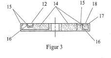
- FIG. 2 shows a perspective view of one of the two side channel base bodies 7 or 8. It consists of a ceramic disc 14 and a plastic body 15, in this plan view of the plastic body 15, only the side channel 12 and 13, respectively you can see.
- the ceramic disk 14 has a slot 16 which is approximately a Partial ring forms.
- the plastic body 15 forms the side channel 12th or 13 off.
- the taper of the cross section of the side channel 12 and 13 achieved by reducing its depth. It should be clear be that the manufacturing accuracy of the slot 16 is not particularly high needs because inaccuracies by the slot 16 filling plastic body 15 be balanced. That is why the efficiency of the side channel pump 1 the manufacturing accuracy of the side channels 12 and 13 relevant and not the Manufacturing accuracy of the slot 16.
- the impeller 9 and its blades in direct contact With the surface 18 of the ceramic disk it is for the wear resistance crucial that the surface 18 is particularly smooth, for example, by the surface is made by honing or lapping.
- the remaining surfaces of the ceramic disc 14 are rough to the connection between the ceramic disc 14 and the plastic body 15th in addition to support.
- the plastic body 15 engages in this embodiment the outer periphery of the ceramic disc 14 around in the circumferential shoulder 17 and thus ensures a fixation of the ceramic disc 14 in the plastic body 15th
Landscapes
- Engineering & Computer Science (AREA)
- Mechanical Engineering (AREA)
- General Engineering & Computer Science (AREA)
- Structures Of Non-Positive Displacement Pumps (AREA)
Description
mindestens einem Pumpenwerk, das Flüssigkeit vom Einlaß des Pumpenwerkes zum Auslaß des Pumpenwerkes fördert, wobei das Pumpenwerk zumindest einen ersten Seitenkanalgrundkörper, einen zweiten Seitenkanalgrundkörper und ein dazwischen angeordnetes drehbares Laufrad aufweist, wobei das Laufrad in beiden Axialwänden einen miteinander verbundenen Schaufelkranz und jeder Seitenkanalgrundkörper einen in Laufrichtung des Laufrades sich verjüngenden Seitenkanal aufweist.
Aus DE 196 34 253 A1 und US 6,095,771 ist eine zweistufige Seitenkanalpumpe mit einem Pumpenwerk, das zwischen zwei Seitenkanalgrundkörpem angeordnet ist, bekannt. Der dem Auslass zugeordnete Seitenkanalgrundkörperweist eine keramische Scheibe und einen Kunststoffkörper auf. Die keramische Scheibe weist eine Bohrung für einen Vorsprung des Kunststoffkörpers auf, um die keramische Scheibe und den Kunststoffkörper drehfest zueinander anzuordnende. Der dem Auslass zugeordnete Seitenkanalgrundkörper weist gemäß US 6,095,771 einen Seitenkanal auf, der entweder von der keramischen Scheibe oder durch einen Schlitz in der keramischen Scheibe, der mit einer mit den Schlitz korrespondierenden außerhalb der keramischen Scheibe angeordneten Vertiefung in dem Kunststoffkörper zusammenwirkt, ausgebildet wird.
Durch diese Erfindung ist es möglich die Vorteile der Werkstoffe Keramik und Kunststoff für eine Seitenkanalpumpe zu kombinieren, indem die vom Seitenkanalgrundkörper zu erfüllenden Funktionen auf die keramische Scheibe und den Kunststoffkörper aufgeteilt werden. So kann der Verbundkörper durch die Eigenschaften des Kunststoffmaterials gleichzeitig die direkte Lagerung der Antriebswelle ohne zusätzliches Bauteil darstellen.
Dadurch dass mit Ausnahme der dem Laufrad zugewandten Fläche die Flächen der keramischen Scheibe rau sind, bieten sie eine Oberfläche, die es dem Kunststoffkörper, der durch Spritzguß auf die keramische Scheibe aufgebracht wird, erlaubt, sich besonders wirkungsvoll mit der keramischen Scheibe zu verbinden. Erheblich verbessert wird der Halt, indem die keramische Scheibe auf der dem Laufrad zugewandten Seite am Umfang geeignete Maßnahmen z. B. Verzahnung, Absatz etc. aufweist. Denn dann kann der Kunststoffkörper um den äußeren Umfang der keramischen Scheibe herum den umlaufenden Absatz umgreifen, so dass die keramische Scheibe im Kunststoffkörper vollständig fixiert ist. Dadurch ist es möglich den so gebildeten Seitenkanalgrundkörper so in der Seitenkanalpumpe anzuordnen, dass eine axiale Kraft, um die keramische Scheibe und den Kunststoffkörper zusammenzuhalten, nicht zwingend erforderlich ist. Dem Kunststoffkörper kann während des Spritzgießens durch ein entsprechend gestaltetes Werkzeug mit hoher Genauigkeit die Form des Seitenkanals im Schlitz der keramischen Scheibe aufgeprägt werden, wodurch die Genauigkeit der Ausbildung des Seitenkanals erheblich verbessert wird. Die Schwankungen der Querschnittsfläche des Seitenkanalelemets werden also deutlich verringert.
Durch diese Vorgehensweise ist die Herstellung dieser Seitenkanalpumpe in besonderer Weise für die Großserienfertigung geeignet, da zeit- und kostenintensive Bearbeitungsschritte wegfallen können. Die Querschnittsverjüngung des Seitenkanals durch Veränderung seiner Breite und/oder Tiefe wird bereits während des Spritzgießens mit hoher Genauigkeit ausgebildet, so daß keine anschließende Bearbeitung notwendig ist. Bei der keramischen Scheibe handelt es sich um einen Körper, der nur wenig von einer Grundform abweicht und ist somit deutlich einfacher herzustellen.
Claims (8)
- Seitenkanalpumpe mit einem Gehäuse (2), einem Antrieb (5) und mindestens einem Pumpenwerk (6), das Flüssigkeit von einem Einlaß (3) des Pumpenwerkes zu einem Auslaß (4) des Pumpenwerkes (6) fördert, wobei das Pumpenwerk (6) zumindest einen ersten Seitenkanalgrundkörper (7), einen zweiten Seitenkanalgrundkörper (8) und ein dazwischen angeordnetes drehbares Laufrad (9) aufweist, wobei das Laufrad (9) in beiden Axialwänden einen miteinander verbundenen Schaufelkranz (10, 11) und jeder Seitenkanatgrundkörper (7, 8) einen in Laufrichtung des Laufrades sich verjüngenden Seitenkanal (12, 13) aufweist, und der erste und/oder der zweite Seitenkanalgrund körper (7, 8) aus einer einen Schlitz (16) aufweisenden keramischen Scheibe (14) und einem mit der keramischen Scheibe verbundenen Kunstsffkörper (15) besteht, der im Schlitz (16) die Form des Seitenkanals (12, 13) des ersten und/oder zweiten Seitenkanalgrund körpers (7, 8) ausbildet.
- Seitenkanalpumpe nach Anspruch 1, dadurch gekennzeichnet, dass die keramische Scheibe (14) auf der dem Laufrad (9) zugewandten Seite am Umfang einen oder mehrere Absätze (17) aufweist und der Kunststoffkörper (15) die umlaufenden Absätze der keramischen Scheibe (17) ganz oder teilweise ausfüllt.
- Seitenkanalpumpe nach Anspruch 1 oder 2, dadurch gekennzeichnet, dass zumindest einer der Kunststoffkörper (15) integraler Bestandteil des Gehäuses (2) ist.
- Seitenkanalpumpe nach einem der Ansprüche 1 bis 3, dadurch gekennzeichnet, daß ein Einlaß (3) integraler Bestandteil des Kunststoffkörpers (7) ist.
- Seitenkanalpumpe nach einem der Ansprüche 1 bis 4, dadurch gekennzeichnet, dass die keramische Scheibe (14) auf der zum Laufrad (9) weisenden Fläche (18) glatt und auf allen anderen Flächen, insbesondere zu der dem Laufrad (9) abgewandten Seite, rau ist.
- Seitenkanalpumpe nach Anspruch 5, dadurch gekennzeichnet, dass die zum Pumpenrad (9) weisenden Fläche (18) durch Honen oder Läppen hergestellt ist.
- Seitenkanalpumpe nach einem der Ansprüche 1 bis 6, dadurch gekennzeichnet, dass der vom Kunststoffkörper (15) ausgebildete Seitenkanal (12 bzw. 13) seine Querschnittsverjüngung durch Verringerung der Breite und/oder Tiefe des Seitenkanals (12 bzw. 13) erfährt.
- Seitenkanalpumpe nach einen der Anspruche 1 bis 7, dadurch gekennzeichnet, dass der Kunststoffkörper (15) aus einem nicht im kraftstoffquellenden, formstabilen Kunststoff besteht.
Priority Applications (1)
| Application Number | Priority Date | Filing Date | Title |
|---|---|---|---|
| EP04026112A EP1503082B1 (de) | 2002-01-11 | 2002-09-10 | Seitenkanalgrundkörper für eine Seitenkanalpumpe |
Applications Claiming Priority (2)
| Application Number | Priority Date | Filing Date | Title |
|---|---|---|---|
| DE10200791 | 2002-01-11 | ||
| DE10200791A DE10200791A1 (de) | 2002-01-11 | 2002-01-11 | Seitenkanalpumpe |
Related Child Applications (1)
| Application Number | Title | Priority Date | Filing Date |
|---|---|---|---|
| EP04026112A Division EP1503082B1 (de) | 2002-01-11 | 2002-09-10 | Seitenkanalgrundkörper für eine Seitenkanalpumpe |
Publications (2)
| Publication Number | Publication Date |
|---|---|
| EP1329637A1 EP1329637A1 (de) | 2003-07-23 |
| EP1329637B1 true EP1329637B1 (de) | 2005-03-16 |
Family
ID=7711885
Family Applications (2)
| Application Number | Title | Priority Date | Filing Date |
|---|---|---|---|
| EP04026112A Expired - Lifetime EP1503082B1 (de) | 2002-01-11 | 2002-09-10 | Seitenkanalgrundkörper für eine Seitenkanalpumpe |
| EP02020217A Expired - Lifetime EP1329637B1 (de) | 2002-01-11 | 2002-09-10 | Seitenkanalpumpe |
Family Applications Before (1)
| Application Number | Title | Priority Date | Filing Date |
|---|---|---|---|
| EP04026112A Expired - Lifetime EP1503082B1 (de) | 2002-01-11 | 2002-09-10 | Seitenkanalgrundkörper für eine Seitenkanalpumpe |
Country Status (3)
| Country | Link |
|---|---|
| US (1) | US6755610B2 (de) |
| EP (2) | EP1503082B1 (de) |
| DE (3) | DE10200791A1 (de) |
Families Citing this family (4)
| Publication number | Priority date | Publication date | Assignee | Title |
|---|---|---|---|---|
| DE10327321A1 (de) * | 2003-06-16 | 2005-01-13 | Siemens Ag | Als G-Rotorpumpe ausgebildete Verdrängerpumpe |
| JP4534677B2 (ja) * | 2003-10-31 | 2010-09-01 | 株式会社デンソー | 燃料ポンプ |
| RU2338884C1 (ru) * | 2007-01-18 | 2008-11-20 | Иван Иванович Пеньков | Роторно-вихревая машина с керамическими рабочими элементами |
| CN105782028A (zh) * | 2016-04-25 | 2016-07-20 | 域西机械技术(上海)有限公司 | 结构陶瓷在凸轮泵上的应用 |
Family Cites Families (5)
| Publication number | Priority date | Publication date | Assignee | Title |
|---|---|---|---|---|
| DE4243225A1 (de) * | 1992-12-19 | 1994-06-23 | Pierburg Gmbh | Brennstoffpumpe |
| DE19634253A1 (de) | 1995-12-30 | 1997-07-03 | Bosch Gmbh Robert | Aggregat zum Fördern von Kraftstoff |
| DE19704403B4 (de) * | 1997-02-06 | 2006-10-05 | Ti Automotive (Neuss) Gmbh | Brennstoffpumpe |
| US6435810B1 (en) * | 2000-10-20 | 2002-08-20 | Delphi Technologies, Inc. | Wear resistant fuel pump |
| US6454521B1 (en) * | 2000-11-15 | 2002-09-24 | Delphi Technologies, Inc. | Wear resistant fuel pump |
-
2002
- 2002-01-11 DE DE10200791A patent/DE10200791A1/de not_active Withdrawn
- 2002-09-10 DE DE50202475T patent/DE50202475D1/de not_active Expired - Lifetime
- 2002-09-10 EP EP04026112A patent/EP1503082B1/de not_active Expired - Lifetime
- 2002-09-10 EP EP02020217A patent/EP1329637B1/de not_active Expired - Lifetime
- 2002-09-10 DE DE50205893T patent/DE50205893D1/de not_active Expired - Lifetime
- 2002-12-20 US US10/325,175 patent/US6755610B2/en not_active Expired - Fee Related
Also Published As
| Publication number | Publication date |
|---|---|
| US20030133784A1 (en) | 2003-07-17 |
| US6755610B2 (en) | 2004-06-29 |
| EP1503082A1 (de) | 2005-02-02 |
| DE50205893D1 (de) | 2006-04-27 |
| DE10200791A1 (de) | 2003-07-24 |
| DE50202475D1 (de) | 2005-04-21 |
| EP1329637A1 (de) | 2003-07-23 |
| EP1503082B1 (de) | 2006-02-22 |
Similar Documents
| Publication | Publication Date | Title |
|---|---|---|
| DE69927078T2 (de) | Kombiniertes Lager | |
| DE1961299A1 (de) | Zusammengesetzte Riemenscheibe,beispielsweise fuer Lichtmaschinen in Kraftfahrzeugen,bestehend aus einem vorzugsweise auf dem Wege der spanlosen Formung hergestellten Scheibenteil mit Riemenrille aus Blech und mit Nabe sowie einem Luefterkranz | |
| EP0243718B1 (de) | Bauteil aus einem spritz- oder giessbaren polymeren Werkstoff | |
| EP4198310B1 (de) | Schraubenspindelpumpe | |
| EP2094980A2 (de) | Lagerschale für eine hydrostatische maschine und hydrostatische maschine mit dieser lagerschale | |
| DE60102885T2 (de) | Verschleissbeständige Kraftstoffpumpe | |
| DE102016103396A1 (de) | Bremsbelag einer Scheibenbremse und Bremsbelagsatz | |
| DE102004002847B4 (de) | KFZ-Zahnradanordnung für ein KFZ-Hilfsgetriebe und Verfahren zum Herstellen einer solchen KFZ-Zahnradanordnung | |
| DE1901964A1 (de) | Gehaeuse,insbesondere fuer eine Zahnradmaschine,und Verfahren zu dessen Herstellung | |
| EP1503082B1 (de) | Seitenkanalgrundkörper für eine Seitenkanalpumpe | |
| DE60309292T2 (de) | Dichtungsvorrichtung | |
| DE4332480C2 (de) | Hydraulisch dämpfendes Gummilager | |
| DE19543516C2 (de) | Transportelement für flächiges Gut | |
| EP2464853B1 (de) | Hochdruckpumpe | |
| DE2018132B2 (de) | Laufrolle für Auszugsschienen von Schubladen | |
| DE29802228U1 (de) | Lagerschild | |
| EP1777422A1 (de) | Pleuel für eine Kolbenarbeitsmaschine | |
| DE102015013215A1 (de) | Mehrteiliges Hochleistungskettenrad | |
| DE102014216643A1 (de) | Hauptlager für eine Kurbelwelle eines Verbrennungsmotors | |
| DE19963481A1 (de) | Aus einem Blech geformtes Exenterstück | |
| DE69112701T2 (de) | Kreiselpumpe. | |
| DE8628385U1 (de) | Fahrwerk, vorzugsweise für Müllbehälter | |
| DE102020133825A1 (de) | Lüfterrad mit Verstärkungsring | |
| DE3601720A1 (de) | Freilauf | |
| DE2243595A1 (de) | Scheibenbremse |
Legal Events
| Date | Code | Title | Description |
|---|---|---|---|
| PUAI | Public reference made under article 153(3) epc to a published international application that has entered the european phase |
Free format text: ORIGINAL CODE: 0009012 |
|
| 17P | Request for examination filed |
Effective date: 20020910 |
|
| AK | Designated contracting states |
Designated state(s): AT BE BG CH CY CZ DE DK EE ES FI FR GB GR IE IT LI LU MC NL PT SE SK TR |
|
| AX | Request for extension of the european patent |
Extension state: AL LT LV MK RO SI |
|
| RAP1 | Party data changed (applicant data changed or rights of an application transferred) |
Owner name: TI AUTOMOTIVE (NEUSS) GMBH |
|
| 17Q | First examination report despatched |
Effective date: 20040116 |
|
| AKX | Designation fees paid |
Designated state(s): DE ES FR GB IT |
|
| GRAP | Despatch of communication of intention to grant a patent |
Free format text: ORIGINAL CODE: EPIDOSNIGR1 |
|
| GRAA | (expected) grant |
Free format text: ORIGINAL CODE: 0009210 |
|
| GRAS | Grant fee paid |
Free format text: ORIGINAL CODE: EPIDOSNIGR3 |
|
| AK | Designated contracting states |
Kind code of ref document: B1 Designated state(s): DE ES FR GB IT |
|
| PG25 | Lapsed in a contracting state [announced via postgrant information from national office to epo] |
Ref country code: IT Free format text: LAPSE BECAUSE OF FAILURE TO SUBMIT A TRANSLATION OF THE DESCRIPTION OR TO PAY THE FEE WITHIN THE PRESCRIBED TIME-LIMIT;WARNING: LAPSES OF ITALIAN PATENTS WITH EFFECTIVE DATE BEFORE 2007 MAY HAVE OCCURRED AT ANY TIME BEFORE 2007. THE CORRECT EFFECTIVE DATE MAY BE DIFFERENT FROM THE ONE RECORDED. Effective date: 20050316 Ref country code: GB Free format text: LAPSE BECAUSE OF FAILURE TO SUBMIT A TRANSLATION OF THE DESCRIPTION OR TO PAY THE FEE WITHIN THE PRESCRIBED TIME-LIMIT Effective date: 20050316 |
|
| REG | Reference to a national code |
Ref country code: GB Ref legal event code: FG4D Free format text: NOT ENGLISH |
|
| REF | Corresponds to: |
Ref document number: 50202475 Country of ref document: DE Date of ref document: 20050421 Kind code of ref document: P |
|
| PG25 | Lapsed in a contracting state [announced via postgrant information from national office to epo] |
Ref country code: ES Free format text: LAPSE BECAUSE OF FAILURE TO SUBMIT A TRANSLATION OF THE DESCRIPTION OR TO PAY THE FEE WITHIN THE PRESCRIBED TIME-LIMIT Effective date: 20050627 |
|
| GBV | Gb: ep patent (uk) treated as always having been void in accordance with gb section 77(7)/1977 [no translation filed] |
Effective date: 20050316 |
|
| ET | Fr: translation filed | ||
| PLBE | No opposition filed within time limit |
Free format text: ORIGINAL CODE: 0009261 |
|
| STAA | Information on the status of an ep patent application or granted ep patent |
Free format text: STATUS: NO OPPOSITION FILED WITHIN TIME LIMIT |
|
| 26N | No opposition filed |
Effective date: 20051219 |
|
| PGFP | Annual fee paid to national office [announced via postgrant information from national office to epo] |
Ref country code: DE Payment date: 20100929 Year of fee payment: 9 |
|
| PGFP | Annual fee paid to national office [announced via postgrant information from national office to epo] |
Ref country code: FR Payment date: 20111005 Year of fee payment: 10 |
|
| REG | Reference to a national code |
Ref country code: FR Ref legal event code: ST Effective date: 20130531 |
|
| PG25 | Lapsed in a contracting state [announced via postgrant information from national office to epo] |
Ref country code: DE Free format text: LAPSE BECAUSE OF NON-PAYMENT OF DUE FEES Effective date: 20130403 |
|
| PG25 | Lapsed in a contracting state [announced via postgrant information from national office to epo] |
Ref country code: FR Free format text: LAPSE BECAUSE OF NON-PAYMENT OF DUE FEES Effective date: 20121001 |
|
| REG | Reference to a national code |
Ref country code: DE Ref legal event code: R119 Ref document number: 50202475 Country of ref document: DE Effective date: 20130403 |