EP1329403A2 - Device for automatic aligning of cord bands being unwound - Google Patents
Device for automatic aligning of cord bands being unwound Download PDFInfo
- Publication number
- EP1329403A2 EP1329403A2 EP02025213A EP02025213A EP1329403A2 EP 1329403 A2 EP1329403 A2 EP 1329403A2 EP 02025213 A EP02025213 A EP 02025213A EP 02025213 A EP02025213 A EP 02025213A EP 1329403 A2 EP1329403 A2 EP 1329403A2
- Authority
- EP
- European Patent Office
- Prior art keywords
- magnetic
- cord
- band
- cord band
- suction
- Prior art date
- Legal status (The legal status is an assumption and is not a legal conclusion. Google has not performed a legal analysis and makes no representation as to the accuracy of the status listed.)
- Granted
Links
Images


Classifications
-
- B—PERFORMING OPERATIONS; TRANSPORTING
- B65—CONVEYING; PACKING; STORING; HANDLING THIN OR FILAMENTARY MATERIAL
- B65H—HANDLING THIN OR FILAMENTARY MATERIAL, e.g. SHEETS, WEBS, CABLES
- B65H35/00—Delivering articles from cutting or line-perforating machines; Article or web delivery apparatus incorporating cutting or line-perforating devices, e.g. adhesive tape dispensers
-
- B—PERFORMING OPERATIONS; TRANSPORTING
- B65—CONVEYING; PACKING; STORING; HANDLING THIN OR FILAMENTARY MATERIAL
- B65H—HANDLING THIN OR FILAMENTARY MATERIAL, e.g. SHEETS, WEBS, CABLES
- B65H19/00—Changing the web roll
- B65H19/10—Changing the web roll in unwinding mechanisms or in connection with unwinding operations
- B65H19/18—Attaching, e.g. pasting, the replacement web to the expiring web
- B65H19/1842—Attaching, e.g. pasting, the replacement web to the expiring web standing splicing, i.e. the expiring web being stationary during splicing contact
- B65H19/1852—Attaching, e.g. pasting, the replacement web to the expiring web standing splicing, i.e. the expiring web being stationary during splicing contact taking place at a distance from the replacement roll
-
- B—PERFORMING OPERATIONS; TRANSPORTING
- B65—CONVEYING; PACKING; STORING; HANDLING THIN OR FILAMENTARY MATERIAL
- B65H—HANDLING THIN OR FILAMENTARY MATERIAL, e.g. SHEETS, WEBS, CABLES
- B65H2301/00—Handling processes for sheets or webs
- B65H2301/40—Type of handling process
- B65H2301/46—Splicing
- B65H2301/461—Processing webs in splicing process
- B65H2301/4611—Processing webs in splicing process before splicing
- B65H2301/46115—Processing webs in splicing process before splicing by bringing leading edge to splicing station, e.g. by chain or belt
-
- B—PERFORMING OPERATIONS; TRANSPORTING
- B65—CONVEYING; PACKING; STORING; HANDLING THIN OR FILAMENTARY MATERIAL
- B65H—HANDLING THIN OR FILAMENTARY MATERIAL, e.g. SHEETS, WEBS, CABLES
- B65H2301/00—Handling processes for sheets or webs
- B65H2301/40—Type of handling process
- B65H2301/46—Splicing
- B65H2301/462—Form of splice
- B65H2301/4621—Overlapping article or web portions
-
- B—PERFORMING OPERATIONS; TRANSPORTING
- B65—CONVEYING; PACKING; STORING; HANDLING THIN OR FILAMENTARY MATERIAL
- B65H—HANDLING THIN OR FILAMENTARY MATERIAL, e.g. SHEETS, WEBS, CABLES
- B65H2301/00—Handling processes for sheets or webs
- B65H2301/40—Type of handling process
- B65H2301/46—Splicing
- B65H2301/464—Splicing effecting splice
- B65H2301/46412—Splicing effecting splice by element moving in a direction perpendicular to the running direction of the web
-
- B—PERFORMING OPERATIONS; TRANSPORTING
- B65—CONVEYING; PACKING; STORING; HANDLING THIN OR FILAMENTARY MATERIAL
- B65H—HANDLING THIN OR FILAMENTARY MATERIAL, e.g. SHEETS, WEBS, CABLES
- B65H2555/00—Actuating means
- B65H2555/10—Actuating means linear
- B65H2555/11—Actuating means linear pneumatic, e.g. inflatable elements
-
- B—PERFORMING OPERATIONS; TRANSPORTING
- B65—CONVEYING; PACKING; STORING; HANDLING THIN OR FILAMENTARY MATERIAL
- B65H—HANDLING THIN OR FILAMENTARY MATERIAL, e.g. SHEETS, WEBS, CABLES
- B65H2555/00—Actuating means
- B65H2555/10—Actuating means linear
- B65H2555/13—Actuating means linear magnetic, e.g. induction motors
-
- B—PERFORMING OPERATIONS; TRANSPORTING
- B65—CONVEYING; PACKING; STORING; HANDLING THIN OR FILAMENTARY MATERIAL
- B65H—HANDLING THIN OR FILAMENTARY MATERIAL, e.g. SHEETS, WEBS, CABLES
- B65H2801/00—Application field
- B65H2801/93—Tyres
Definitions
- the invention relates to a device for automatic alignment of the leading beginning section of one unwound from a supply roll Cord tape, especially a steel cord tape, for splicing on the trailing end of the cord band of the previous supply roll.
- the invention is therefore based on the object of a device for automatic Aligning the material before splicing to create a gentle Alignment allows, so that ultimately only the actual splice must be cut out and practically no other waste occurs.
- such a device is characterized according to the invention by suction or provided with reversible drive devices Magnetic rollers for the adhesive attachment of the sagging start section the cord band, preferably two parallel one above the other arranged suction or magnetic rollers are provided and in front of the lower suction or Magnetic roller at least one axially displaceable against springs on both sides mounted deflection roller is arranged.
- the arrangement according to the invention ensures that when the Cordbandes when the suction or magnetic rollers start, to which the leading one Beginning of the new supply roll off-center and possibly also has been set at an incline due to the different pulling action both side edges of the tape when tightening directed transversely to the running direction Force components occur that move the belt off-center Let the position slide inwards.
- the arrangement according to the invention is preferably suitable, although it is also suitable for Suction rolls and textile cord tapes are conceivable for steel cord tapes with magnetic rolls for the alignment device, since these magnetic rollers are extremely smooth can be so that the shear force components that occur during clamping the soft steel cord tape without the risk of deformation in the middle position slide.
- an embodiment of the invention can be provided be that after tensioning the steel cord and a certain Lateral shift of the obliquely placed cord band end the alignment device stopped and reversed automatically, that is, a bit in the opposite direction runs, so that the tape sags again without starting to rest the pulleys.
- the jerk when tightening again by putting on at the pulleys is the time at which the lateral sliding movement of the cord tape that is still off-center works best.
- This Multiple actuation can be programmed automatically, for example tense and reversed six times with each alignment the cord strip end that has been pulled off the supply roll in six successive steps in the middle position.
- the axial possibility of displacement against springs on both sides the pulley is important, otherwise the frictional force of the cord band the deflection roller the lateral displacement of the cord end by the shear force components block on the suction or magnetic rollers or at least would hinder.
- the side springs bring the after every alignment step Deflection pulleys back into the central exit length, which also favors this is that, depending on the individual alignment steps, the drive device for the Suction or magnetic rollers are reversed, making the cord strap stronger again slack and therefore no longer or only with very little investment power to the Deflection pulleys are still present.
- the splice bar for connecting the end of the expired cord roll with the beginning section of the new cord tape supply roll can preferably be parallel to be arranged between the magnetic rollers, with sensors for detection the band end edges of the steel cord bands to be connected can control.
- the end section 2 with the expired End section 3 of the previous cord roll is to be spliced.
- an automatic alignment device 4 is provided according to the invention, the alignment of the leading start section 2 of the cord band 5 takes over from the new supply roll 1.
- a follower role to wind up the separating tape 7 between the individual sticky ones Cordbandlagen.
- 8 and 9 are the take-off rolls of the subsequent processing station for the cord band and 10 shows a dancer role.
- the device according to the invention comprises - in the illustrated embodiment the cord band 5 should be a steel cord band - two magnetic rollers 11 and 12, which are spaced one above the other, with the counter bar between them 13 is arranged for the splice bar 14.
- These magnetic rollers alternate from magnetic and non-magnetic disks and enable tacking the cord end 2 by simply pressing it on.
- a deflection roller 15 is arranged, one for cases another feed from the supply roll 1 there is a further deflection roller 16 is, as can be seen in particular from Fig. 1b, as a hollow roller is axially displaceably mounted on a shaft 17 on both sides against springs 18, 19.
- the drive motor for driving the magnetic rollers 11 and 12 is indicated.
- the deflection rollers 15, 16 serve the purpose of minimal Limit the bending radius when aligning. They are pivoted and can be easily moved laterally on the axis 17 so that they are aligned show little resistance. Bring after each alignment step the lateral springs 18, 19 the guide rollers 15, 16 in the central starting position back.
- the cord band by reversing the drive device for the magnetic rollers 11 and 12 retracted until the band edge 21 exactly with the through the Cross 22 specified response position of the sensor 23 coincides. Subsequently the splice bar 14 is actuated and the two cord ends 2 and 3 overlapping spliced together. Because of the exact alignment of this Cord ends 2 and 3 against each other then only need to be cut out the actual splice. Further waste sections by warping and offset of the bands 2 and 3 against each other do not occur. additionally to the sensors 23 and 24 for the band edge 21 of the band section 2 of the new Cord 5 to be removed are still sensors 25 for stopping the take-off rollers 8, 9 in the corresponding desired end position of the band edge 26 of the End 3 of the previous supply roll is provided.
Abstract
Description
Die Erfindung bezieht sich auf eine Vorrichtung zum automatischen Ausrichten des vorlaufenden Anfangsabschnittes eines von einer Vorratsrolle abgewickelten Cordbandes, insbesondere eines Stahlcordbandes, zum Anspleißen an das nachlaufende Ende des Cordbandes der vorherigen Vorratsrolle.The invention relates to a device for automatic alignment of the leading beginning section of one unwound from a supply roll Cord tape, especially a steel cord tape, for splicing on the trailing end of the cord band of the previous supply roll.
Beim Wechsel von einer Cordbandrolle zur nächsten Cordbandrolle muss das Ende der abgelaufenen Rolle an den Anfangsabschnitt der neuen Cordbandrolle angespleißt werden. Hierzu ist es bisher üblich, dass das Material vom Bediener manuell an eine Magnetleiste im Bereich der Spleißleiste - gegebenenfalls ist die Spleißleiste selbst als Magnetleiste ausgebildet - angelegt wird, wobei durch das schräge Abschneiden der Bandenden und das Durchhängen sowie das Sich-Verziehen des ja sehr weichen unvulkanisierten Cordbandes beim Ausrichten Spannungen und Verformungen auftreten, sodass nach dem Aneinanderspleißen große Abschnitte als unbrauchbar wieder herausgeschnitten werden müssen. Dies unterbricht nicht nur den Fertigungsprozess, sondern ist wegen des hohen Abfallanteils auch sehr teuer.When changing from one cord reel to the next cord reel, the end must of the expired roll spliced onto the start section of the new cord band roll become. So far it has been customary for the material to be removed by the operator manually on a magnetic strip in the area of the splice strip - if necessary, the Splice bar itself designed as a magnetic bar - is created, whereby by the sloping cutting of the tape ends and sagging and warping of the very soft unvulcanized cord tape when aligning Tensions and deformations occur so that after splicing large sections have to be cut out as unusable. This not only interrupts the manufacturing process, but is due to the high proportion of waste also very expensive.
Der Erfindung liegt daher die Aufgabe zugrunde, eine Vorrichtung zum automatischen Ausrichten des Materials vor dem Anspleißen zu schaffen, das ein schonendes Ausrichten ermöglicht, sodass letztendlich lediglich die eigentliche Spleißstelle herausgeschnitten werden muss und praktisch kein sonstiger Abfall auftritt.The invention is therefore based on the object of a device for automatic Aligning the material before splicing to create a gentle Alignment allows, so that ultimately only the actual splice must be cut out and practically no other waste occurs.
Zur Lösung dieser Aufgabe ist eine solche Vorrichtung erfindungsgemäß gekennzeichnet durch mit reversierbaren Antriebseinrichtungen versehene Saug- oder Magnetrollen zum anhaftenden Befestigen des nach unten durchhängenden Anfangsabschnittes des Cordbandes, wobei bevorzugt zwei parallel übereinander angeordnete Saug- oder Magnetrollen vorgesehen sind und vor der unteren Saugoder Magnetrolle wenigstens eine axial nach beiden Seiten gegen Federn verschiebbar gelagerte Umlenkrolle angeordnet ist. To achieve this object, such a device is characterized according to the invention by suction or provided with reversible drive devices Magnetic rollers for the adhesive attachment of the sagging start section the cord band, preferably two parallel one above the other arranged suction or magnetic rollers are provided and in front of the lower suction or Magnetic roller at least one axially displaceable against springs on both sides mounted deflection roller is arranged.
Durch die erfindungsgemäße Anordnung wird erreicht, dass beim Spannen des Cordbandes beim Anlaufen der Saug- oder Magnetrollen, an die das vorlaufende Anfangsende der neuen Vorratsrolle außermittig und gegebenenfalls auch noch schräg geneigt angesetzt worden ist, durch die unterschiedliche Zugwirkung an beiden Seitenkanten des Bandes beim Straffen quer zur Laufrichtung gerichtete Kraftkomponenten auftreten, die das Band aus seiner außermittig versetzten Stellung nach innen gleiten lassen.The arrangement according to the invention ensures that when the Cordbandes when the suction or magnetic rollers start, to which the leading one Beginning of the new supply roll off-center and possibly also has been set at an incline due to the different pulling action both side edges of the tape when tightening directed transversely to the running direction Force components occur that move the belt off-center Let the position slide inwards.
Bevorzugt eignet sich die erfindungsgemäße Anordnung, obgleich sie auch für Saugrollen und Textilcordbänder denkbar ist, für Stahlcordbänder mit Magnetrollen für die Ausrichtvorrichtung, da diese Magnetrollen außerordentlich glatt ausgebildet sein können, sodass die beim Spannen auftretenden Querkraftkomponenten das weiche Stahlcordband ohne die Gefahr von Verformungen in die Mittelstellung gleiten lassen.The arrangement according to the invention is preferably suitable, although it is also suitable for Suction rolls and textile cord tapes are conceivable for steel cord tapes with magnetic rolls for the alignment device, since these magnetic rollers are extremely smooth can be so that the shear force components that occur during clamping the soft steel cord tape without the risk of deformation in the middle position slide.
Um Blockierungen zu vermeiden, kann dabei in Ausgestaltung der Erfindung vorgesehen sein, dass nach einem Spannen des Stahlcordbandes und einer gewissen Seitenverschiebung des schräg aufgesetzten Cordbandendes die Ausrichtvorrichtung angehalten und automatisch reversiert wird, das heißt, ein Stückchen in die Gegenrichtung läuft, sodass das Band zunächst wieder durchhängt, ohne an den Umlenkrollen anzuliegen. Der Ruck beim Wieder-Spannen durch das Anlegen an die Umlenkrollen ist nämlich der Zeitpunkt, bei dem die seitliche Verrutschbewegung des noch außermittig sitzenden Cordbandes am Besten funktioniert. Diese Mehrfachbetätigung kann automatisch einprogrammiert sein, sodass beispielsweise bei jedem Ausrichten grundsätzlich sechs Mal angespannt und wieder reversiert wird, um das von der Vorratsrolle abgezogene Cordbandende in sechs aufeinanderfolgenden Schritten in die Mittelstellung auszurichten.In order to avoid blockages, an embodiment of the invention can be provided be that after tensioning the steel cord and a certain Lateral shift of the obliquely placed cord band end the alignment device stopped and reversed automatically, that is, a bit in the opposite direction runs, so that the tape sags again without starting to rest the pulleys. The jerk when tightening again by putting on at the pulleys is the time at which the lateral sliding movement of the cord tape that is still off-center works best. This Multiple actuation can be programmed automatically, for example tense and reversed six times with each alignment the cord strip end that has been pulled off the supply roll in six successive steps in the middle position.
Selbstverständlich wird bei dem Ausrichten das Band nur um größenordnungsmäßig
20 cm, also das Ausmaß des Durchhängens des von der Vorratsrolle abgezogenen
Abschnitts mithilfe der Saug- oder Magnetrollen in Längsrichtung bewegt,
da ja nach dem Straffen im Anschluss an das Sich-anlegen an die Umlenkrollen
das Bandende an den Saug- oder Magnetrollen sowohl in Förderrichtung als auch
quer dazu abrutscht. Wichtig für die erfindungsgemäße Ausrichtung ist die Querverrutschung,
die automatisch zu einer Verschiebung in die gewünschte Mittelstellung
führt.Of course, when aligning the tape is only of the order of
Die axiale, nach beiden Seiten gegen Federn gegebene Verschiebemöglichkeit der Umlenkrolle ist wichtig, da ansonsten die Reibungskraft des Cordbandes an der Umlenkrolle die seitliche Verschiebung des Cordbandendes durch die Querkraftkomponenten an den Saug- oder Magnetrollen blockieren oder zumindest behindern würde. Nach jedem Ausrichtschritt bringen die seitlichen Federn die Umlenkrollen in die mittige Ausgangslange zurück, was noch dadurch begünstigt wird, dass ja nach den einzelnen Ausrichtschritten die Antriebsvorrichtung für die Saug- oder Magnetrollen reversiert und damit das Cordband ja wieder stärker durchhängt und somit nicht mehr oder nur mit sehr geringer Anlagekraft an den Umlenkrollen noch anliegt.The axial possibility of displacement against springs on both sides the pulley is important, otherwise the frictional force of the cord band the deflection roller the lateral displacement of the cord end by the shear force components block on the suction or magnetic rollers or at least would hinder. The side springs bring the after every alignment step Deflection pulleys back into the central exit length, which also favors this is that, depending on the individual alignment steps, the drive device for the Suction or magnetic rollers are reversed, making the cord strap stronger again slack and therefore no longer or only with very little investment power to the Deflection pulleys are still present.
Bei Verwendung der bei Stahlcordbändern bevorzugt verwendeten Magnetrollen, sollen diese abwechselnd aus magnetischen und unmagnetischen Scheiben geschichtet sein.When using the magnetic rollers preferred for steel cord tapes, these should alternately be layered from magnetic and non-magnetic disks his.
Die Spleißleiste zur Verbindung des Endes der abgelaufenen Cordbandrolle mit dem Anfangsabschnitt der neuen Cordband-Vorratsrolle kann bevorzugt parallel zur den Magnetrollen zwischen diesen angeordnet sein, wobei Sensoren zur Erfassung der Bandendkanten der zu verbindenden Stahlcordbänder die Funktion steuern können.The splice bar for connecting the end of the expired cord roll with the beginning section of the new cord tape supply roll can preferably be parallel to be arranged between the magnetic rollers, with sensors for detection the band end edges of the steel cord bands to be connected can control.
Weitere Vorteile, Merkmale und Einzelheiten der Erfindung ergeben sich aus der nachfolgenden Beschreibung eines Ausführungsbeispiels sowie anhand der Zeichnung. Dabei zeigen:
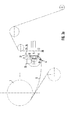
- Fig. 1a
- eine Seitenansicht einer erfindungsgemäßen Ausrichtvorrichtung zwischen einer Cordband-Vorratsrolle und den Abzugsrollen zum Weitertransport zu den Bearbeitungsstationen des Cordbandes in der Ausgangsposition,
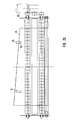
- Fig. 1b
- eine Stirnansicht der Ausrichtvorrichtung in Richtung des Pfeils P in Fig. 1 mit strichpunktiert eingezeichneter außermittig versetzt und verkippt angesetztem Cordbandende in der Ausgangsstellung.
- Fig. 2a
- eine Seitenansicht der Anordnung nach dem Ausrichten des Cordbandes,
- Fig. 2b
- eine Stirnansicht der Ausrichtvorrichtung in der Stellung nach Fig. 2a.
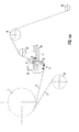
- Fig. 3a
- eine Seitenansicht und
- Fig. 3b
- eine Stirnansicht der Ausrichtvorrichtung nach dem Wieder-zurückfahren des ausgerichteten Cordbandes in eine sensorgesteuerte Spleißausgangsstellung und
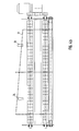
- Fig. 4a und 4b
- Seitenansicht und Stirnansicht der Ausrichtvorrichtung mit integrierter Spließleiste beim Anspleißen der beiden Cordbandenden aneinander.
- Fig. 1a
- 2 shows a side view of an alignment device according to the invention between a cord band supply roll and the take-off rolls for further transport to the processing stations of the cord band in the starting position,
- Fig. 1b
- an end view of the alignment device in the direction of arrow P in Fig. 1 with dash-dotted line offset and tilted attached cord end in the starting position.
- Fig. 2a
- a side view of the arrangement after aligning the cord band,
- Fig. 2b
- an end view of the alignment device in the position of FIG. 2a.
- Fig. 3a
- a side view and
- Fig. 3b
- a front view of the alignment device after moving the aligned cord band back into a sensor-controlled splice starting position and
- 4a and 4b
- Side view and front view of the alignment device with integrated locking strip when the two cord ends are spliced together.
Bei 1 erkennt man eine Cordband-Vorratsrolle, deren Endabschnitt 2 mit dem abgelaufenen
Endabschnitt 3 der vorherigen Cordbandrolle verspleißt werden soll.
Um dieses Verspleißen ohne große Verspannungen und Versetzungen durchführen
zu können, ist erfindungsgemäß eine automatische Ausrichtvorrichtung 4 vorgesehen,
die das Ausrichten des vorlaufenden Anfangsabschnittes 2 des Cordbandes
5 von der neuen Vorratsrolle 1 übernimmt. Bei 6 erkennt man eine Mitläuferrolle
zum Aufwickeln des Trennbandes 7 zwischen den einzelnen klebrigen
Cordbandlagen. 8 und 9 sind die Abzugsrollen der anschließenden Verarbeitungsstation
für das Cordband und 10 zeigt eine Tänzerrolle.At 1 you can see a cord tape supply roll, the
Die erfindungsgemäße Vorrichtung umfasst - im dargestellten Ausführungsbeispiel
soll das Cordband 5 ein Stahlcordband sein - zwei Magnetrollen 11 und 12,
die in Abstand übereinander angeordnet sind, wobei zwischen ihnen die Gegenleiste
13 für die Spleißleiste 14 angeordnet ist. Diese Magnetrollen bestehen abwechselnd
aus magnetischen und nichtmagnetischen Scheiben und ermöglichen
ein Anheften des Cordbandendes 2 durch einfaches Andrücken. Unterhalb der
unteren Magnetrolle 11 ist eine Umlenkrolle 15 angeordnet, wobei für Fälle einer
anderen Zuführung von der Vorratsrolle 1 noch eine weitere Umlenkrolle 16 vorhanden
ist, die, wie man insbesondere aus Fig. 1b erkennen kann, als Hohlwalze
auf einer Welle 17 beidseits gegen Federn 18, 19 axial verschiebbar gelagert ist.
Bei 20 ist der Antriebsmotor zum Antreiben der Magnetrollen 11 und 12 angedeutet.The device according to the invention comprises - in the illustrated embodiment
the
Nachdem ein Bediener den Endabschnitt 2 des Stahlcordbandes 5 wie in Fig. 1b
versetzt und seitlich verschoben an die Magnetrollen 11 und 12 angeheftet hat,
werden diese in Rotation versetzt und spannen dabei das Stahlcordband in die
Stellung nach den Figuren 2a und 2b. Dabei strafft sich bei schief angebrachtem
Bandende 2 die eine Seite eher als die andere. Hierdurch wird eine seitliche Kraft
auf das Bandende 2 erzeugt, die dieses in Richtung Mittelachse der Magnetrollen
fördert, bis beide Seiten gleichstraff sind. Wenn beide Seiten gleichstraff sind, ist
das Material fertig ausgerichtet. Diese in Fig. 2a und 2b dargestellte ausgerichtete
Stellung wird im Allgemeinen aber nicht durch einmaliges Betätigen der Magnetrollen
erreicht, sondern durch einen mehrstufigen Prozess, bei dem die Magnetrollen
nach einem Anfahren und Straffen des Bandes (dies wird selbstverständlich
nicht weiter von der feststehenden Vorratsrolle 1 abgezogen, sondern rutscht mit
der seitlichen Verschiebung auch in Förderrichtung auf den Magnetrollen 11 und
12 durch , das heißt, in Längsrichtung oberhalb der Magnetrolle 12 verschiebt sich
die Bandkante nur, um den Unterschied zwischen dem durchhängenden Band 5 in
Fig. 1a und dem gestrafften Band in Fig. 2a) umgesteuert werden, sodass das
Band wieder in die Position nach Fig. 1a zurückläuft. Anschließend wird erneut
angefahren und das Band wiederum gestrafft, da gerade im Augenblick des
Straffens, das heißt des unsymmetrischen Straffens der einen Seitenkante gegenüber
der anderen Seitenkante, eine besonders hohe Kraftkomponente in Querrichtung
und damit ein gutes seitliches Verschieben in die gewünschte ausgerichtete
Mittelstellung nach Fig. 2b erzeugt wird. Als zweckmäßig hat es sich dabei
erwiesen, die Ausrichtvorrichtung mit einem Schrittsteuerprogramm für sechs Ausrichtschritte
zu versehen. Die Umlenkrollen 15, 16 erfüllen den Zweck, den minimalen
Biegeradius beim Ausrichten zu begrenzen. Sie sind drehbar gelagert und
können seitlich auf der Achse 17 leicht verschoben werden, sodass sie dem Ausrichten
wenig Widerstand entgegenbringen. Nach jedem Ausrichtschritt bringen
die seitlichen Federn 18, 19 die Umlenkrollen 15, 16 in die mittige Ausgangslage
zurück.After an operator has finished the
Nach dem erfolgten Ausrichten gemäß Fig. 2b wird, wie in den Fig. 3a und 3b dargestellt
ist, das Cordband durch Umsteuern der Antriebsvorrichtung für die Magnetrollen
11 und 12 zurückgefahren, bis die Bandkante 21 exakt mit der durch das
Kreuz 22 angegebenen Ansprechposition des Sensors 23 zusammenfällt. Anschließend
wird die Spleißleiste 14 betätigt und die beiden Cordbandenden 2 und
3 überlappend miteinander verspleißt. Wegen der exakten Ausrichtung dieser
Cordbandenden 2 und 3 gegeneinander bedarf es anschließend nur des Herausschneidens
der eigentlichen Spleißstelle. Weitere Abfallabschnitte durch Verziehen
und Versetzen der Bänder 2 und 3 gegeneinander fallen nicht an. Zusätzlich
zu den Sensoren 23 und 24 für die Bandkante 21 des Bandabschnitts 2 des neu
abzuziehenden Cordbandes 5 sind noch Sensoren 25 zum Anhalten der Abzugsrollen
8, 9 in der entsprechenden gewünschten Endstellung der Bandkante 26 des
Bandendes 3 der vorherigen Vorratsrolle vorgesehen.After the alignment according to FIG. 2b has taken place, as shown in FIGS. 3a and 3b
is, the cord band by reversing the drive device for the
Claims (7)
Applications Claiming Priority (2)
| Application Number | Priority Date | Filing Date | Title |
|---|---|---|---|
| DE10201369 | 2002-01-16 | ||
| DE10201369A DE10201369C1 (en) | 2002-01-16 | 2002-01-16 | Device for automatically aligning cord strips to be unwound |
Publications (3)
| Publication Number | Publication Date |
|---|---|
| EP1329403A2 true EP1329403A2 (en) | 2003-07-23 |
| EP1329403A3 EP1329403A3 (en) | 2003-10-01 |
| EP1329403B1 EP1329403B1 (en) | 2005-04-06 |
Family
ID=7712228
Family Applications (1)
| Application Number | Title | Priority Date | Filing Date |
|---|---|---|---|
| EP02025213A Expired - Lifetime EP1329403B1 (en) | 2002-01-16 | 2002-11-12 | Device for automatic aligning of cord bands being unwound |
Country Status (5)
| Country | Link |
|---|---|
| US (1) | US20030141020A1 (en) |
| EP (1) | EP1329403B1 (en) |
| JP (1) | JP4149798B2 (en) |
| KR (1) | KR20030062239A (en) |
| DE (2) | DE10201369C1 (en) |
Cited By (1)
| Publication number | Priority date | Publication date | Assignee | Title |
|---|---|---|---|---|
| EP2295355A3 (en) * | 2009-09-10 | 2011-09-28 | Krones AG | Method, device and adhesive tape for splicing label tapes and spliceable label tape |
Families Citing this family (4)
| Publication number | Priority date | Publication date | Assignee | Title |
|---|---|---|---|---|
| US20050241774A1 (en) * | 2004-04-30 | 2005-11-03 | Kimberly-Clark Worldwide, Inc. | Apparatus and process for aligning materials during a splice |
| DE102004032528C5 (en) * | 2004-07-06 | 2012-04-05 | Khs Gmbh | A method of performing a roll change in a supply unit for feeding a sheet-like sheet to a packaging machine or the like processing machine and supply unit for performing this method |
| EP2709937A4 (en) * | 2011-05-18 | 2015-04-29 | Hydro Québec | Ferromagnetic metal ribbon transfer apparatus and method |
| CN103182616A (en) * | 2011-12-29 | 2013-07-03 | 中冶赛迪工程技术股份有限公司 | Strip postprocessing wire centring device and usage thereof |
Citations (5)
| Publication number | Priority date | Publication date | Assignee | Title |
|---|---|---|---|---|
| US3132544A (en) * | 1959-03-25 | 1964-05-12 | Sonobond Corp | Positioning and splicing apparatus for positioning and splicing webs |
| US3654035A (en) * | 1969-02-26 | 1972-04-04 | Fuji Photo Film Co Ltd | Web butt splicing apparatus |
| US4190475A (en) * | 1978-05-16 | 1980-02-26 | Marquip, Inc. | Paper roll web splicing |
| US4450039A (en) * | 1982-08-23 | 1984-05-22 | Harris Graphics Corporation | Web splicing apparatus |
| US5388387A (en) * | 1993-03-12 | 1995-02-14 | Kliklok Corporation | Packaging film feeding and splicing apparatus and method |
Family Cites Families (10)
| Publication number | Priority date | Publication date | Assignee | Title |
|---|---|---|---|---|
| US3908980A (en) * | 1973-08-02 | 1975-09-30 | Alexander Fowler | Work loading, unloading, and positioning means for handling sheet material in power presses and the like |
| US3903770A (en) * | 1973-11-15 | 1975-09-09 | Alexander Fowler | Shear feeding system to front gauges using magnetic delivery means and a vertically yielding support table |
| JPS625844A (en) * | 1985-07-02 | 1987-01-12 | Toyo Tire & Rubber Co Ltd | Connecting device for rubber-covered core |
| US5049222A (en) * | 1989-06-01 | 1991-09-17 | Mitsubishi Jukogyo Kabushiki Kaisha | Method and apparatus for feeding materials in a tire building machine |
| DE4309013C2 (en) * | 1993-03-20 | 1996-09-05 | Fischer Maschf Karl E | Splicer |
| US5477912A (en) * | 1993-09-28 | 1995-12-26 | Aluminum Company Of America | Roll for use in a belt caster and an associated method |
| US5697277A (en) * | 1994-05-17 | 1997-12-16 | Best Cutting Die Company | Multi use rotary die plate system |
| US5849123A (en) * | 1995-12-20 | 1998-12-15 | Eastman Kodak Company | Apparatus and method for aligning webs |
| US5728036A (en) * | 1996-07-10 | 1998-03-17 | Hazelett Strip-Casting Corporation | Elongated finned backup rollers having multiple magnetized fins for guiding and stabilizing an endless, flexible, heat-conducting casting belt |
| US6454686B1 (en) * | 2001-04-30 | 2002-09-24 | T.D. Wright, Inc. | Modular magnetic cylinder |
-
2002
- 2002-01-16 DE DE10201369A patent/DE10201369C1/en not_active Expired - Lifetime
- 2002-11-12 EP EP02025213A patent/EP1329403B1/en not_active Expired - Lifetime
- 2002-11-12 DE DE50202702T patent/DE50202702D1/en not_active Expired - Lifetime
- 2002-11-26 US US10/304,643 patent/US20030141020A1/en not_active Abandoned
- 2002-12-25 JP JP2002373363A patent/JP4149798B2/en not_active Expired - Lifetime
-
2003
- 2003-01-03 KR KR10-2003-0000241A patent/KR20030062239A/en not_active Application Discontinuation
Patent Citations (5)
| Publication number | Priority date | Publication date | Assignee | Title |
|---|---|---|---|---|
| US3132544A (en) * | 1959-03-25 | 1964-05-12 | Sonobond Corp | Positioning and splicing apparatus for positioning and splicing webs |
| US3654035A (en) * | 1969-02-26 | 1972-04-04 | Fuji Photo Film Co Ltd | Web butt splicing apparatus |
| US4190475A (en) * | 1978-05-16 | 1980-02-26 | Marquip, Inc. | Paper roll web splicing |
| US4450039A (en) * | 1982-08-23 | 1984-05-22 | Harris Graphics Corporation | Web splicing apparatus |
| US5388387A (en) * | 1993-03-12 | 1995-02-14 | Kliklok Corporation | Packaging film feeding and splicing apparatus and method |
Cited By (1)
| Publication number | Priority date | Publication date | Assignee | Title |
|---|---|---|---|---|
| EP2295355A3 (en) * | 2009-09-10 | 2011-09-28 | Krones AG | Method, device and adhesive tape for splicing label tapes and spliceable label tape |
Also Published As
| Publication number | Publication date |
|---|---|
| US20030141020A1 (en) | 2003-07-31 |
| DE50202702D1 (en) | 2005-05-12 |
| DE10201369C1 (en) | 2003-07-24 |
| KR20030062239A (en) | 2003-07-23 |
| EP1329403B1 (en) | 2005-04-06 |
| EP1329403A3 (en) | 2003-10-01 |
| JP4149798B2 (en) | 2008-09-17 |
| JP2003226450A (en) | 2003-08-12 |
Similar Documents
| Publication | Publication Date | Title |
|---|---|---|
| DE2451149C2 (en) | Device for rolling up and compressing a flexible, compressible strip | |
| DE3151100C2 (en) | ||
| EP3715293B1 (en) | Material sheet retraction device | |
| EP0968919B1 (en) | Method and device for enveloping quadrangular objects with a tape-like enveloping material | |
| EP2707288A2 (en) | Method for actuating the band driving device of a strapping machine and corresponding strapping machine | |
| EP0138745B1 (en) | Driving pulley for a slat conveyor | |
| WO2008012126A1 (en) | Supply device | |
| WO2003051751A1 (en) | Device for producing foil rolls | |
| DE2238370A1 (en) | INSTALLATION AND PROCEDURE FOR LEVELING A METAL STRIP | |
| AT518608B1 (en) | Kantenanleimvorrichtung | |
| DE3900251C2 (en) | ||
| DE10201369C1 (en) | Device for automatically aligning cord strips to be unwound | |
| EP0439830A2 (en) | Web-processing device | |
| DE2547507C2 (en) | Method and device for drawing off and feeding an unvulcanized rubber sheet from a supply roll onto a tire building drum | |
| EP0352564B1 (en) | Method and apparatus for handling and subsequent treatment of a honeycomb web | |
| DE2111160B2 (en) | DEVICE FOR FEEDING METALLIZED STRIPS IN A PLATE PRESS PROCESSING FILM MATERIAL | |
| WO2005080240A2 (en) | Devices for preparing a storage roll wound with a web of material for a flying roll change | |
| DE2022577C3 (en) | Method and device for producing a weld seam on a film envelope placed under tension around a stack of packs | |
| EP1776215B1 (en) | Device for drawing in veneer strips | |
| DE202013102342U1 (en) | Splicing device for splicing cord material | |
| EP1280725B1 (en) | Device and method for tensioning a flat material web, which is to be conveyed, by effecting a difference in rotational speed | |
| EP3693302B1 (en) | Adhesive piece | |
| EP0719228A1 (en) | Method and device for packaging profiles | |
| DE4425417C1 (en) | Automatic belt transfer device | |
| EP0847923B1 (en) | Apparatus for strapping articles |
Legal Events
| Date | Code | Title | Description |
|---|---|---|---|
| PUAI | Public reference made under article 153(3) epc to a published international application that has entered the european phase |
Free format text: ORIGINAL CODE: 0009012 |
|
| AK | Designated contracting states |
Designated state(s): AT BE BG CH CY CZ DE DK EE ES FI FR GB GR IE IT LI LU MC NL PT SE SK TR |
|
| AX | Request for extension of the european patent |
Extension state: AL LT LV MK RO SI |
|
| PUAL | Search report despatched |
Free format text: ORIGINAL CODE: 0009013 |
|
| AK | Designated contracting states |
Kind code of ref document: A3 Designated state(s): AT BE BG CH CY CZ DE DK EE ES FI FR GB GR IE IT LI LU MC NL PT SE SK TR |
|
| AX | Request for extension of the european patent |
Extension state: AL LT LV MK RO SI |
|
| RIC1 | Information provided on ipc code assigned before grant |
Ipc: 7B 65H 23/10 B Ipc: 7B 65H 19/18 B Ipc: 7B 65H 69/00 B Ipc: 7B 65H 21/00 A |
|
| 17P | Request for examination filed |
Effective date: 20031108 |
|
| AKX | Designation fees paid |
Designated state(s): CZ DE NL SK |
|
| RBV | Designated contracting states (corrected) |
Designated state(s): CZ DE NL SK |
|
| 17Q | First examination report despatched |
Effective date: 20040727 |
|
| GRAP | Despatch of communication of intention to grant a patent |
Free format text: ORIGINAL CODE: EPIDOSNIGR1 |
|
| GRAS | Grant fee paid |
Free format text: ORIGINAL CODE: EPIDOSNIGR3 |
|
| GRAA | (expected) grant |
Free format text: ORIGINAL CODE: 0009210 |
|
| AK | Designated contracting states |
Kind code of ref document: B1 Designated state(s): CZ DE NL SK |
|
| REG | Reference to a national code |
Ref country code: IE Ref legal event code: FG4D Free format text: LANGUAGE OF EP DOCUMENT: GERMAN |
|
| REF | Corresponds to: |
Ref document number: 50202702 Country of ref document: DE Date of ref document: 20050512 Kind code of ref document: P |
|
| PLBE | No opposition filed within time limit |
Free format text: ORIGINAL CODE: 0009261 |
|
| STAA | Information on the status of an ep patent application or granted ep patent |
Free format text: STATUS: NO OPPOSITION FILED WITHIN TIME LIMIT |
|
| 26N | No opposition filed |
Effective date: 20060110 |
|
| PGFP | Annual fee paid to national office [announced via postgrant information from national office to epo] |
Ref country code: NL Payment date: 20211119 Year of fee payment: 20 Ref country code: SK Payment date: 20211103 Year of fee payment: 20 Ref country code: CZ Payment date: 20211102 Year of fee payment: 20 Ref country code: DE Payment date: 20211111 Year of fee payment: 20 |
|
| REG | Reference to a national code |
Ref country code: DE Ref legal event code: R071 Ref document number: 50202702 Country of ref document: DE |
|
| REG | Reference to a national code |
Ref country code: NL Ref legal event code: MK Effective date: 20221111 |
|
| REG | Reference to a national code |
Ref country code: SK Ref legal event code: MK4A Ref document number: E 125 Country of ref document: SK Expiry date: 20221112 |
|
| PG25 | Lapsed in a contracting state [announced via postgrant information from national office to epo] |
Ref country code: SK Free format text: LAPSE BECAUSE OF EXPIRATION OF PROTECTION Effective date: 20221112 Ref country code: CZ Free format text: LAPSE BECAUSE OF EXPIRATION OF PROTECTION Effective date: 20221112 |