EP1776215B1 - Device for drawing in veneer strips - Google Patents
Device for drawing in veneer strips Download PDFInfo
- Publication number
- EP1776215B1 EP1776215B1 EP05742891A EP05742891A EP1776215B1 EP 1776215 B1 EP1776215 B1 EP 1776215B1 EP 05742891 A EP05742891 A EP 05742891A EP 05742891 A EP05742891 A EP 05742891A EP 1776215 B1 EP1776215 B1 EP 1776215B1
- Authority
- EP
- European Patent Office
- Prior art keywords
- stop
- veneer
- belt
- roller
- transport
- Prior art date
- Legal status (The legal status is an assumption and is not a legal conclusion. Google has not performed a legal analysis and makes no representation as to the accuracy of the status listed.)
- Not-in-force
Links
Images


Classifications
-
- B—PERFORMING OPERATIONS; TRANSPORTING
- B27—WORKING OR PRESERVING WOOD OR SIMILAR MATERIAL; NAILING OR STAPLING MACHINES IN GENERAL
- B27D—WORKING VENEER OR PLYWOOD
- B27D1/00—Joining wood veneer with any material; Forming articles thereby; Preparatory processing of surfaces to be joined, e.g. scoring
- B27D1/10—Butting blanks of veneer; Joining same along edges; Preparatory processing of edges, e.g. cutting
Definitions
- the invention relates to a device for feeding veneer strips into a veneer assembly machine, in which individual veneer strips are assembled substantially along the fiber direction.
- Veneer splicing machines are known in the prior art in various configurations. Such machines usually have a transport device consisting of an upper and a lower transport chain, by means of which the veneer strips are guided over a heating zone and are thereby pressed together at their abutting edges. The veneer strips have at their abutting edges on an adhesive which can be cured by means of heating in the heating zone. The heat triggers a chemical reaction in the adhesive, which hardens it and the veneer strips are glued together.
- a veneer assembly machine which has a transport device with movable transport members.
- the transport chains are arranged obliquely tapering to one another, wherein between the two transport chains, a circulating heating band is provided, which is driven by the chains.
- the known veneer splicing machines have problems in terms of their throughput time and manufacturing costs, since the indentations record the veneer strips at a standstill and then accelerate them to the speed of the transport chains. Only in the continuously running transport chains then the veneer strips are glued together. This results in an intermittent and a continuous transport function, which can be realized only by two drives or by a correspondingly complex circuit with coupling.
- doors in particular room doors, with designs are increasingly desired lately, which have a so-called Intarsienst Shape at various points.
- the device according to the invention for feeding veneer strips into a veneer assembly machine has the advantage that it can be produced in a particularly simple and cost-effective manner. This can be dispensed with according to the invention, in particular complicated additional drives and / or clutches.
- a belt drive comprising a belt is provided for this purpose, which is arranged between an insertion region for the veneers and the actual transport device of the veneer assembly machine.
- a two-part stop device is in the transport direction of the belt drive something of a remote from the machine vertex of the belt drive, ie the vertex near the insertion area for the veneer strips, spaced.
- the two-piece stop device comprises a first element arranged above the belt and a second element arranged laterally of the belt.
- the second element can be moved back and forth between two positions, wherein in one first position a stop for the veneer strips is provided and in the second position a transfer and transport of the veneer strips on the belt drive is made possible to supply the veneer strips of the assembly machine.
- a laying device is arranged at the insertion area.
- the application device comprises a first and a second stop, wherein a veneer strip between the first and the second stop can be applied and aligned.
- This veneer strip is preferably an inlay strip which can be aligned between the two stops, and further veneer strips can each be fed laterally from the inlay strip so that at least three strips can be fed simultaneously to the veneer splicer. This makes it possible to quickly and safely produce veneers with intarsia strips.
- a further advantage of the feed device according to the invention is that the cycle time of the machine can be reduced since the next veneer strips can be applied immediately after the veneer strips have been completely pulled in. As a result, even during the passage of the first veneer strips through the veneer assembly machine, the following veneer strips can be fed via the draw-in, so that an almost continuous composition of veneer strips is made possible.
- the first stop and the second stop of the application device are each formed as a wall. This allows a safe investment of an inlay strip between the two walls and at the same time the intarsia strips facing away from the walls can serve as stops for the two adjacent veneer strips.
- the application device has a U-shaped in section, wherein a veneer strip inserted between the two stops can be placed on the bottom of the U-shaped application device.
- the second element of the stop means has an inclined surface.
- a clamping function can also be provided between the two elements of the stop device, so that the inserted veneer strips are easily clamped to the stop device. This allows a secure positioning of the veneer strips on the feeder.
- the second element is formed as a roll, so that also a tapered or wedge-shaped stop for the veneer strips can be provided.
- the second element of the stop device is preferably arranged on both sides of the belt drive.
- the second element is particularly preferably designed as a U-shaped rocker with inclined end faces, one leg each of the U-shaped rocker being arranged on one side of the belt.
- the U-shaped rocker is simply moved by pivoting between the stop position and the transfer position.
- the second element of the stop device is designed as a U-shaped probe with inclined end surfaces.
- the U-shaped button is moved back and forth by a linear, ie vertical, movement between its two positions. It should be noted that by the U-shaped configuration of the second element the Actuation is possible via a common drive. Of course, it is also possible to provide two separate components for the second element of the stop device, which can each be operated separately.
- the first element of the stop device is designed as a role.
- the role of their own weight exert a required pressure on the veneer strip to allow safe transfer to the belt drive.
- an additional force acting on the roller which is for example by means of a spring or pneumatically or hydraulically applied to increase the pressure.
- a contact point of the stop device lies in a plane perpendicular to the transport direction through a pivot point of the roller.
- the contact point is spaced from this plane in the transport direction to ensure a particularly safe onward transport.
- an elastic ring is preferably arranged on the roller.
- the elastic ring can in particular compensate for differences in thickness of the individual veneer strips.
- a further roller which is arranged in the transport direction after the feed roller, provided to ensure safe transport of the between the To ensure both veneers inserted veneer strip.
- the middle veneer strip is pressed by the weight of the additional role on the underlying conveyor belt.
- a spring can be provided to press the other role with an additional force on the middle veneer strip.
- the device according to the invention has at least one feed roller, which is provided at the insertion area and under which the veneer strips are laid.
- the feed roller is inclined to the transport direction of the belt. This ensures that the veneer strips are already pressed together in the loading state something or if a divider is present, pressed against this divider. This allows a supply to the catchment area in exactly aligned position of the applied veneer strip.
- the belt drive is preferably operated continuously and particularly preferably a drive of the belt drive is effected via a shaft of the transport device of the veneer assembly machine.
- a drive of the belt drive is effected via a shaft of the transport device of the veneer assembly machine.
- no separate drive must be provided for the belt drive of the feeder and the speed of the belt drive corresponds exactly to the speed of the transport device.
- no complex synchronization devices or devices for monitoring the velocities of the belt drive or the transport device have to be provided.
- the belt drive is preferably driven via a lower transport device of the veneer assembly machine.
- two drive wheels, eg gears are preferably provided for driving the transport device of the assembly machine, and a drive wheel for: the belt drive is placed between the two gears on the same shaft.
- a sensor is preferably provided to detect a stop position of the veneer strips on the stop device and / or to detect a complete insertion of the veneer strips into the veneer assembly machine.
- the veneer assembly machine 1 comprises, in a known manner, a transport device with a lower transport chain 19 and an upper transport chain 21.
- the lower transport chain 19 is driven via a shaft 14 and gears 20a, 20b in the direction of the arrow (see FIG.
- the upper transport chain 21 is driven via a shaft 12 and gears 22a, 22b in the direction of the arrow (see FIG.
- Between the two transport chains 19, 21 at least two juxtaposed veneer strips are transported in a known manner to a heater (not shown) to connect the two veneer strips together.
- the veneer assembly machine 1 further comprises a feeder 2, which is shown in detail in Figs. 4 to 6.
- a feeder 2 comprises a two-part stopper 3, which is formed from a first stop element 4 and a second stop element 7, which touch each other at a contact point K.
- the first stop element 4 comprises a roller 5 and an actuating element 6
- the second stop element 7 comprises a rocker 8 and an actuating element 9.
- the first stop element 4 is movable in the vertical direction and the second stop element 7 is around a pivot axis S pivotally.
- the rocker 8 has an inclined to the transport plane or transport direction X of the veneer strip surface 8a, which is formed substantially U-shaped (see Fig. 6).
- the feeder 2 comprises a belt drive with a revolving belt 10, a first deflecting roller 11 mounted on a shaft 12 and a second deflecting roller 13 mounted on the shaft 14.
- the belt drive is transmitted via the shaft 14 common with the toothed wheels 20a, 20b and the second Guide roller 13 at the same speed as the lower conveyor chain 19 driven.
- the feeder 2 comprises an insertion region 15, which can be seen in particular from FIG. 3 and is arranged adjacent to the first deflection roller 11.
- the insert area 15 comprises a base plate, not shown, on which the veneer strips 16 can be placed.
- a separating web 18 is provided, to which the two veneer strips 16 are applied in the manner shown in Fig. 3.
- two feed rollers 17a, 17b are arranged on the insertion area 15, one of the feed rollers being arranged on the right or left of the separating web 18 in each case.
- the two feed rollers 17a, 17b are slightly inclined to the separating web 18 (by approx.
- the veneer strips are pressed by the feed rollers 17a, 17b respectively in the direction of the separating web 18. Due to their weight force, the feed rollers 17a, 17b exert a predetermined force on the veneer strips 16. It should be noted, however, that in order to support the pressing force of the feed rollers 17a, 17b additionally a spring force or a hydraulic or pneumatic force can be applied.
- the stopper 3 forms in the initial position between the first stop member 4th and the second stop member 7 is a tapered stop.
- the two feed rollers 17a, 17b support a movement of the two veneer strips 16 relative to each other , If the veneer strips 16 are further advanced, they hit the inclined surface 8a of the rocker 8 and are slightly guided upwards slightly.
- the stopper 3 forms in its initial position a tapered stop, consisting of a shell portion of the roller 5 and the inclined surface 8a, so that the two adjoining the stopper 3 veneer strips not only abut there, but also easily are clamped between the first stop element 4 and the second stop element 7.
- the reached stop position can now either be recognized by the operator or it is a sensor, such as a light barrier or a push button sensor, provided which detects the stop position of the two veneer strips 16.
- the next step is either manually by the operator or by detecting the Stop position automatically pivoted away the second stop member 7 by means of the actuating element 9 down to the pivot axis S.
- the second stop member 7 is below the belt 10, more precisely below the upper run of the belt arranged.
- the belt drive is arranged between the toothed wheels 20a, 20b of the lower transport chain 19, so that the veneer strips 16 conveyed by the belt drive in the transport direction X are advanced between the lower and upper transport chains 19, 21. Since the belt drive has the same speed as the transport chains 19, 21, the two veneer strips are transported without position change by the transport device of the veneer assembly machine and fed to the heating device, so that gluing of the two veneer strips 16 at their abutting edge is possible.
- the inclined surface 8a of the rocker 8 has a substantially U-shaped form, so that in each case a free leg is arranged on one side of the belt 10 of the belt drive.
- the roller 5 of the first stop element 4 has a width which is greater than the width of the belt 10 is such that the roller 5 is at least partially disposed in the region of the legs of the U-shaped, inclined surface 8a of the rocker 8.
- the stopper 3 of the feeder 2 is arranged on the belt drive such that the stopper 3 is slightly offset in the transport direction X from a vertex R of the belt drive at the insertion area 15 in the transport direction X.
- the stop position of the stop 3 (contact point K) is selected such that it lies in a plane perpendicular to the transport direction X, which in FIG. 4 is to the left of a line through the axes of rotation of the shaft 12 the first guide roller 11 and the roller 5 is located.
- the rocker 8 is returned to the starting position shown in FIGS. 1 and 4 by means of the actuating element 9, which can be operated pneumatically or hydraulically, for example. This can either be done manually by the operator or a sensor detected when the veneer strips 16 have been transported past the stopper 3.
- the actuating element 9 which can be operated pneumatically or hydraulically, for example. This can either be done manually by the operator or a sensor detected when the veneer strips 16 have been transported past the stopper 3.
- the belt drive is driven by the transport device of the veneer assembly machine 1, no separate drive or a complicated coupling for the feeder 2 necessary. As a result, the production costs for the collection can be kept very low. Furthermore, this space can be saved on the veneer assembly machine.
- a toothed belt can be used, which e.g. made of plastic. Furthermore, it can be provided that, as soon as the imported veneer strips 16 are transported further by the transport chains 19, 21, the first stop element 4 is moved upward to minimize the frictional resistance during feeding of the veneers and not pulling the veneer strips into the transport chains to hinder. As a result, tensions and dents in the veneer strips are prevented. Furthermore, it should be noted that the sensor which detects the stop position of the veneer strips 16 on the stopper 3 can also be used to detect when the trailing edge of the veneer strips 16 passes the sensor and then return the stopper 3 to its original position ,
- the stop 3 of the second construction consists of a first stop element 4 and a second stop element 27.
- the second stop element 27 is a substantially U-shaped element 28, which has an inclined surface 28a on each of the two legs. The surface 28a is again relative to Transport direction X inclined (see Fig. 7). Further, the second stop member 27 comprises an actuator 29. As indicated by the arrows in Fig. 7 and 9, the second stop member 27 is not pivoted as in the first embodiment, but moved vertically.
- the starting position is shown in Fig. 7, in which touch the first stop member 4 and the second stop member of the stopper 3 and provide the tapered stop for the veneer strip 16.
- the second position (passage position) of the stopper 3 is shown, in which the second stop member 27 has been lowered down in the vertical direction, so that a passage between the first stop member 4 and the second stop member 27 is formed.
- the veneer strips 16 are drawn by pressing on the first stop element 4 on the belt 10 and transported to the transport device 19, 21 of the machine, the roller 5 constantly exerts a pressure on the veneer strip.
- the function of the feeder 2 according to the second structure corresponds to that of the first structure, so that reference can be made to the description given there.
- the application device 31 according to the invention can be used both with the previously described first construction of the veneer assembly machine according to FIGS. 1 to 6 and with the second structure of the veneer assembly machine according to FIGS. 7 to 10 instead of the separating web.
- the application device 31 is configured essentially U-shaped in section.
- the application device 31 has a first wall-shaped stop 31a and a second wall-shaped stop 31b.
- the distance between the two stops 31a and 31b is selected such that an inlay strip 16c can be inserted and aligned between the two stops 31a and 31b.
- a first veneer strip 16a and a second veneer strip 16b are applied to the sides of the walls of the stops 31a and 31b facing away from the inlay strip 16c.
- the applying device 31 is interchangeably arranged on the veneer assembling machine to exchange different feeding devices with a different pitch of the wall-shaped stoppers 31a and 31b. Thereby, the inlay tires 16c having different widths can be used.
- an additional roller 32 is further provided, which is arranged after the roller 5. Further, an elastic ring 5a is disposed on the roller 5.
- the elastic ring 5a is made of a rubber material, for example.
- the elastic ring 5a has the function of compensating for differences in thickness between the veneer strips 16a, 16b and the inlay strip 16c.
- the auxiliary roller 32 is provided so that the middle, relatively narrow inlay strip 16c is transported sufficiently far, so that it can be taken from the two adjacent wider veneer strips 16a and 16b. For this task it is sufficient if the additional roller 32 presses with its own weight on the IntarsienstMail 16c. As a result, the inlay tire 16 c is set on the revolving belt 10 pressed and transported together with the veneer strips 16a and 16b.
- the veneer strips are inserted into the machine such that first a first wide veneer strip 16b, then the inlay strip 16c and then the second wide veneer strip 16a is pushed into the feeder of the machine. Here they are aligned with the application device 31. Subsequently, the veneer strips are retracted into the veneer splicer as previously described with reference to Figs. 1-10.
- a veneer with an integrated intarsia strip By applying device 31 according to the invention can thus be produced in a simple and cost-effective manner, a veneer with an integrated intarsia strip. Since the application device 31 is provided interchangeably, can also be a quick retooling on IntarsienstMail different widths. It should be noted that the width of the veneer strips 16a, 16b is about 80 mm and the inlay strip 16c has a width of about 5 mm.
Abstract
Description
Die Erfindung betrifft eine Vorrichtung zum Einzug von Furnierstreifen in eine Furnierzusammensetzmaschine, in welcher einzelne Furnierstreifen im Wesentlichen längs zur Faserrichtung zusammengesetzt werden.The invention relates to a device for feeding veneer strips into a veneer assembly machine, in which individual veneer strips are assembled substantially along the fiber direction.
Furnierzusammensetzmaschinen sind aus dem Stand der Technik in unterschiedlichen Ausgestaltungen bekannt. Derartige Maschinen weisen üblicherweise eine aus einer oberen und einer unteren Transportkette bestehende Transporteinrichtung auf, mittels der die Furnierstreifen über eine Heizzone geführt werden und dabei an ihren Stoßkanten- zusammengedrückt werden. Die Furnierstreifen weisen an ihren Stoßkanten einen Klebstoff auf, welcher mittels Erwärmen in der Heizzone ausgehärtet werden kann. Die Wärme löst im Klebstoff eine chemische Reaktion aus, wodurch sich dieser erhärtet und die Furnierstreifen miteinander verklebt werden.Veneer splicing machines are known in the prior art in various configurations. Such machines usually have a transport device consisting of an upper and a lower transport chain, by means of which the veneer strips are guided over a heating zone and are thereby pressed together at their abutting edges. The veneer strips have at their abutting edges on an adhesive which can be cured by means of heating in the heating zone. The heat triggers a chemical reaction in the adhesive, which hardens it and the veneer strips are glued together.
Im Stand der Technik sind verschiedene Verfahren für die Zusammensetzung von Holzfurnieren bekannt, wobei insbesondere die Stumpfverleimung eine große Bedeutung gewonnen hat. Bei den hierfür verwendeten bekannten Maschinen werden die Furnierstreifen von einem Bediener manuell in einen Einzug der Maschine eingelegt. Die Maschine zieht dann auf Betätigung des Bedieners die Furnierstreifen ein und fügt diese zusammen. Für den Einzug in die Maschine werden hierfür Rolleneinzüge und Diskusscheiben-Getriebe verwendet. Ein derartiger Rolleneinzug ist beispielsweise aus der
Aus der
Die bekannten Furnierzusammensetzmaschinen weisen Probleme hinsichtlich ihrer Durchlaufzeit und der Herstellungskosten auf, da die Einzüge die Furnierstreifen im Stillstand aufnehmen und sie dann bis auf die Geschwindigkeit der Transportketten beschleunigen. Erst in den kontinuierlich laufenden Transportketten werden dann die Furnierstreifen zusammengeklebt. Hierdurch ergibt sich eine intermittierende und eine kontinuierliche Transportfunktion, welche nur durch zwei Antriebe oder durch eine entsprechend aufwendige Schaltung mit Kupplung realisiert werden kann.The known veneer splicing machines have problems in terms of their throughput time and manufacturing costs, since the indentations record the veneer strips at a standstill and then accelerate them to the speed of the transport chains. Only in the continuously running transport chains then the veneer strips are glued together. This results in an intermittent and a continuous transport function, which can be realized only by two drives or by a correspondingly complex circuit with coupling.
Ferner werden in jüngster Zeit vermehrt Türen, insbesondere Zimmertüren, mit Designs gewünscht, welche an verschiedenen Stellen einen so genannten Intarsienstreifen aufweisen.Furthermore, doors, in particular room doors, with designs are increasingly desired lately, which have a so-called Intarsienstreifen at various points.
Derartige Furniere mit Intarsienstreifen müssen derzeit aufwendig von Hand hergestellt werden.Such veneers with intarsia strips currently have to be elaborately made by hand.
Es ist daher Aufgabe der vorliegenden Erfindung, eine Vorrichtung zum Einzug von Furnierstreifen in eine Furnierzusammensetzmaschine bereitzustellen, welche bei einfachem Aufbau und einfacher, kostengünstiger Herstellbarkeit einen schnellen und betriebssicheren. Einzug von. Furnierstreifen ermöglicht und insbesondere eine Automatisierung bei der Herstellung von Furnieren mit Intarsienstreifen ermöglicht.It is therefore an object of the present invention to provide a device for the insertion of veneer strips in a veneer splicer, which with a simple structure and simple, cost-effective manufacturability a fast and reliable. Move in from. Veneer strip allows and in particular an automation in the production of veneers with intarsia tires allows.
Diese Aufgabe wird durch eine Vorrichtung mit den Merkmalen des Anspruches 1 gelöst, die Unteransprüche zeigen bevorzugte Weiterbildungen der Erfindung.This object is achieved by a device having the features of claim 1, the dependent claims show preferred developments of the invention.
Die erfindungsgemäße Vorrichtung zum Einzug von Furnierstreifen in eine Furnierzusammensetzmaschine weist dabei den Vorteil auf, dass sie besonders einfach und kostengünstig hergestellt werden kann. Hierbei kann erfindungsgemäß insbesondere auf aufwendige zusätzliche Antriebe und/oder Kupplungen verzichtet werden. Erfindungsgemäß ist dazu ein einen Riemen umfassender Riementrieb vorgesehen, welcher zwischen einem Einlegebereich für die Furniere und der eigentlichen Transporteinrichtung der Furnierzusammensetzmaschine angeordnet ist. Eine zweiteilige Anschlageinrichtung ist in Transportrichtung des Riementriebes etwas von einem von der Maschine abgewandten Scheitelpunkt des Riementriebes, d.h. dem Scheitelpunkt nahe dem Einlegebereich für die Furnierstreifen, beabstandet. Die zweiteilige Anschlageinrichtung umfasst ein erstes, über dem Riemen angeordnetes Element und ein zweites, seitlich des Riemens angeordnetes Element. Das zweite Element kann dabei zwischen zwei Positionen hin- und herbewegt werden, wobei in einer ersten Position ein Anschlag für die Furnierstreifen bereitgestellt wird und in der zweiten Position eine Übergabe und ein- Transport der Furnierstreifen auf dem Riementrieb ermöglicht wird, um die Furnierstreifen der Zusammensetzmaschine zuzuführen. Um erfindungsgemäß Furniere mit Intarsienstreifen herstellen zu können, ist am Einlegebereich eine Anlegevorrichtung angeordnet. Die Anlegevorrichtung umfasst einen ersten und einen zweiten Anschlag, wobei ein Furnierstreifen zwischen dem ersten und dem zweiten Anschlag anlegbar und ausrichtbar ist. Dieser Furnierstreifen ist vorzugsweise ein Intarsienstreifen, welcher zwischen den beiden Anschlägen ausrichtbar ist und weitere Furnierstreifen sind jeweils seitlich des Intarsienstreifens zuführbar, sodass wenigstens drei Streifen gleichzeitig der Furnierzusammensetzmaschine zugeführt werden können. Dadurch können schnell und sicher Furniere mit Intarsienstreifen hergestellt werden.The device according to the invention for feeding veneer strips into a veneer assembly machine has the advantage that it can be produced in a particularly simple and cost-effective manner. This can be dispensed with according to the invention, in particular complicated additional drives and / or clutches. According to the invention, a belt drive comprising a belt is provided for this purpose, which is arranged between an insertion region for the veneers and the actual transport device of the veneer assembly machine. A two-part stop device is in the transport direction of the belt drive something of a remote from the machine vertex of the belt drive, ie the vertex near the insertion area for the veneer strips, spaced. The two-piece stop device comprises a first element arranged above the belt and a second element arranged laterally of the belt. The second element can be moved back and forth between two positions, wherein in one first position a stop for the veneer strips is provided and in the second position a transfer and transport of the veneer strips on the belt drive is made possible to supply the veneer strips of the assembly machine. In order to be able to produce veneers with intarsia strips according to the invention, a laying device is arranged at the insertion area. The application device comprises a first and a second stop, wherein a veneer strip between the first and the second stop can be applied and aligned. This veneer strip is preferably an inlay strip which can be aligned between the two stops, and further veneer strips can each be fed laterally from the inlay strip so that at least three strips can be fed simultaneously to the veneer splicer. This makes it possible to quickly and safely produce veneers with intarsia strips.
Ein weiterer Vorteil der erfindungsgemäßen Einzugsvorrichtung ist, dass die Taktzeit der Maschine verringert werden kann, da unmittelbar nach dem vollständigen Einziehen der Furnierstreifen schon die nächsten Furnierstreifen angelegt werden können. Dadurch können schon während des Durchlaufs der ersten Furnierstreifen durch die Furnierzusammensetzmaschine die nachfolgenden Furnierstreifen über den Einzug zugeführt werden, sodass eine fast kontinuierliche Zusammensetzung von Furnierstreifen ermöglicht wird.A further advantage of the feed device according to the invention is that the cycle time of the machine can be reduced since the next veneer strips can be applied immediately after the veneer strips have been completely pulled in. As a result, even during the passage of the first veneer strips through the veneer assembly machine, the following veneer strips can be fed via the draw-in, so that an almost continuous composition of veneer strips is made possible.
Vorzugsweise ist der erste Anschlag und der zweite Anschlag der Anlegevorrichtung jeweils als eine Wand ausgebildet. Dadurch kann eine sichere Anlage eines Intarsienstreifens zwischen den beiden Wänden erfolgen und gleichzeitig können die dem Intarsienstreifen abgewandten Seiten der Wände als-Anschläge für die beiden benachbarten Furnierstreifen dienen.Preferably, the first stop and the second stop of the application device are each formed as a wall. This allows a safe investment of an inlay strip between the two walls and at the same time the intarsia strips facing away from the walls can serve as stops for the two adjacent veneer strips.
Somit kann eine besonders kompakte und einfache Ausgestaltung der Anlegevorrichtung erreicht werden. Weiter bevorzugt weist die Anlegevorrichtung dabei eine im Schnitt U-förmige Gestalt auf, wobei ein zwischen die beiden Anschlägen eingelegter Furnierstreifen am Boden der U-förmigen Anlegevorrichtung aufgelegt werden kann.Thus, a particularly compact and simple design of the application device can be achieved. More preferably, the application device has a U-shaped in section, wherein a veneer strip inserted between the two stops can be placed on the bottom of the U-shaped application device.
Vorzugsweise weist das zweite Element der Anschlageinrichtung eine geneigte Fläche auf. Dadurch kann neben der Anschlagfunktion auch eine Klemmfunktion, zwischen den beiden Elementen der Anschlageinrichtung bereitgestellt werden, sodass die eingelegten Furnierstreifen leicht an der Anschlageinrichtung klemmen. Dies ermöglicht ein sicheres Positionieren der Furnierstreifen am Einzug. Gemäß einer anderen bevorzugten Ausgestaltung der Erfindung ist das zweite Element als eine Rolle ausgebildet, sodass ebenfalls ein sich verjüngender bzw. keilförmiger Anschlag für die Furnierstreifen bereitgestellt werden kann.Preferably, the second element of the stop means has an inclined surface. As a result, in addition to the stop function, a clamping function can also be provided between the two elements of the stop device, so that the inserted veneer strips are easily clamped to the stop device. This allows a secure positioning of the veneer strips on the feeder. According to another preferred embodiment of the invention, the second element is formed as a roll, so that also a tapered or wedge-shaped stop for the veneer strips can be provided.
Um eine besonders sichere Positionierung der Furnierstreifen zu erreichen, ist das zweite Element der Anschlageinrichtung vorzugsweise an beiden Seiten des Riementriebes angeordnet. Besonders bevorzugt ist hierbei das zweite Element als U-förmige Wippe mit geneigten Endflächen ausgebildet, wobei jeweils ein Schenkel der U-förmigen Wippe an einer Seite des Riemens angeordnet ist. Die U-förmige Wippe wird dabei einfach durch Schwenken zwischen der Anschlagposition und der Übergabeposition bewegt. Gemäß einer anderen bevorzugten Ausgestaltung der vorliegenden Erfindung ist das zweite Element der Anschlageinrichtung als U-förmiger Taster mit geneigten Endflächen ausgebildet. Der U-förmige Taster wird hierbei durch eine lineare, d.h. vertikale, Bewegung zwischen seinen beiden Positionen hin- und herbewegt. Es sei angemerkt, dass durch die U-förmige Ausbildung des zweiten Elements die Betätigung über einen gemeinsamen Antrieb ermöglicht wird. Selbstverständlich ist es jedoch auch möglich, für das zweite Element der Anschlageinrichtung zwei separate Bauteile vorzusehen, welche jeweils auch separat betrieben werden können.In order to achieve a particularly secure positioning of the veneer strips, the second element of the stop device is preferably arranged on both sides of the belt drive. In this case, the second element is particularly preferably designed as a U-shaped rocker with inclined end faces, one leg each of the U-shaped rocker being arranged on one side of the belt. The U-shaped rocker is simply moved by pivoting between the stop position and the transfer position. According to another preferred embodiment of the present invention, the second element of the stop device is designed as a U-shaped probe with inclined end surfaces. The U-shaped button is moved back and forth by a linear, ie vertical, movement between its two positions. It should be noted that by the U-shaped configuration of the second element the Actuation is possible via a common drive. Of course, it is also possible to provide two separate components for the second element of the stop device, which can each be operated separately.
Um eine besonders einfache Übergabe der am Anschlag anliegenden Querstreifen auf den Riementrieb des Einzugs zu ermöglichen, ist das erste Element der Anschlageinrichtung als Rolle ausgebildet. Hierbei kann die Rolle aufgrund ihres Eigengewichtes einen erforderlichen Druck auf die Furnierstreifen ausüben, um eine sichere Übergabe an den Riementrieb zu ermöglichen. Weiterhin kann vorzugsweise noch eine zusätzliche Kraft auf die Rolle wirken, welche beispielsweise mittels einer Feder oder pneumatisch oder hydraulisch ausgeübt wird, um den Druck zu erhöhen.In order to allow a particularly simple transfer of the abutting transverse strip on the belt drive of the feeder, the first element of the stop device is designed as a role. In this case, the role of their own weight exert a required pressure on the veneer strip to allow safe transfer to the belt drive. Furthermore, preferably still an additional force acting on the roller, which is for example by means of a spring or pneumatically or hydraulically applied to increase the pressure.
Vorzugsweise liegt ein Kontaktpunkt der Anschlageinrichtung in einer Ebene senkrecht zur Transportrichtung durch einen Drehpunkt der Rolle. Gemäß einer anderen bevorzugten Ausgestaltung ist der Kontaktpunkt von dieser Ebene in Transportrichtung beabstandet, um einen besonders sicheren Weitertransport zu gewährleisten.Preferably, a contact point of the stop device lies in a plane perpendicular to the transport direction through a pivot point of the roller. According to another preferred embodiment, the contact point is spaced from this plane in the transport direction to ensure a particularly safe onward transport.
Um den zwischen dem ersten und zweiten Anschlag angelegten mittleren Furnierstreifen sicher mit den beiden seitlichen Furnierstreifen zu bewegen, ist vorzugsweise an der Rolle ein elastischer Ring angeordnet. Der elastische Ring kann insbesondere Dickenunterschiede der einzelnen Furnierstreifen ausgleichen.In order to safely move the middle veneer strip applied between the first and second stops with the two lateral veneer strips, an elastic ring is preferably arranged on the roller. The elastic ring can in particular compensate for differences in thickness of the individual veneer strips.
Weiter bevorzugt ist eine weitere Rolle, welche in Transportrichtung nach der Einzugsrolle angeordnet ist, vorgesehen, um einen sicheren Transport des zwischen den beiden Anschlägen eingelegten Furnierstreifens sicher zu stellen. Hierbei wird der mittlere Furnierstreifen vom Eigengewicht der zusätzlichen Rolle auf den herunterliegenden Transportriemen gedrückt. Es sei jedoch angemerkt, dass zusätzlich auch z.B. eine Feder vorgesehen werden kann, um die weitere Rolle mit einer zusätzlichen Kraft auf den mittleren Furnierstreifen zu drücken.Further preferably, a further roller, which is arranged in the transport direction after the feed roller, provided to ensure safe transport of the between the To ensure both veneers inserted veneer strip. Here, the middle veneer strip is pressed by the weight of the additional role on the underlying conveyor belt. It should be noted, however, that in addition, for example, a spring can be provided to press the other role with an additional force on the middle veneer strip.
Weiter bevorzugt weist die erfindungsgemäße Vorrichtung wenigstens eine Zuführrolle auf, welche am Einlegebereich vorgesehen ist und unter welche die Furnierstreifen gelegt werden. Die Zuführrolle ist dabei zur Transportrichtung des Riemens schräg gestellt. Hierdurch wird erreicht, dass die Furnierstreifen schon im Einlegezustand etwas aneinandergedrückt werden bzw. falls ein Trennsteg vorhanden ist, gegen diesen Trennsteg gedrückt werden. Dies ermöglicht eine Zufuhr zum Einzugsbereich in exakt ausgerichteter Position der angelegten Furnierstreifen.More preferably, the device according to the invention has at least one feed roller, which is provided at the insertion area and under which the veneer strips are laid. The feed roller is inclined to the transport direction of the belt. This ensures that the veneer strips are already pressed together in the loading state something or if a divider is present, pressed against this divider. This allows a supply to the catchment area in exactly aligned position of the applied veneer strip.
Der Riementrieb wird vorzugsweise kontinuierlich betrieben und besonders bevorzugt erfolgt ein Antrieb des Riementriebes über eine Welle der Transporteinrichtung der Furnierzusammensetzmaschine. Dadurch muss für den Riementrieb des Einzuges kein separater Antrieb vorgesehen werden und die Geschwindigkeit des Riementriebes entspricht genau der Geschwindigkeit der Transporteinrichtung. Dadurch müssen keine aufwendigen Synchronisierungseinrichtungen oder Einrichtungen zur Überwachung der Geschwindigkeiten des Riementriebs bzw. der Transporteinrichtung vorgesehen werden. Vorzugsweise ist der Riementrieb dabei über eine untere Transporteinrichtung der Furnierzusammensetzmaschine angetrieben. Dabei sind vorzugsweise für den Antrieb der Transporteinrichtung der Zusammensetzmaschine zwei Antriebsräder, z.B. Zahnräder, vorgesehen, und ein Antriebsrad für: den Riementrieb ist zwischen den beiden Zahnrädern auf der gleichen Welle angeordnet.The belt drive is preferably operated continuously and particularly preferably a drive of the belt drive is effected via a shaft of the transport device of the veneer assembly machine. As a result, no separate drive must be provided for the belt drive of the feeder and the speed of the belt drive corresponds exactly to the speed of the transport device. As a result, no complex synchronization devices or devices for monitoring the velocities of the belt drive or the transport device have to be provided. The belt drive is preferably driven via a lower transport device of the veneer assembly machine. In this case, two drive wheels, eg gears, are preferably provided for driving the transport device of the assembly machine, and a drive wheel for: the belt drive is placed between the two gears on the same shaft.
Um eine weitere Verkürzung der Durchlaufzeit der Furnierstreifen zu erreichen, ist vorzugsweise ein Sensor vorgesehen, um eine Anschlagposition der Furnierstreifen an der Anschlageinrichtung zu erfassen und/oder um einen vollständigen Einzug der Furnierstreifen in die Furnierzusammensetzmaschine zu erfassen.In order to achieve a further shortening of the passage time of the veneer strips, a sensor is preferably provided to detect a stop position of the veneer strips on the stop device and / or to detect a complete insertion of the veneer strips into the veneer assembly machine.
Nachfolgend werden unter Bezugnahme auf die begleitende Zeichnungen bevorzugte Ausführungsbeispiele der Erfindung beschrieben. In der Zeichnung ist:
- Fig. 1
- eine schematische. Seitenansicht eines Teils einer Furnierzusammensetzmaschine mit einem Einzug gemäß einem ersten Aufbau
- Fig. 2
- eine schematische Draufsicht der Maschine von Fig. 1,
- Fig. 3
- eine schematische, perspektivische Ansicht der in den Fig. 1 und 2 gezeigten Maschine,
- Fig. 4
- eine Seitenansicht des Einzugs der Maschine gemäß dem ersten Aufbau,
- Fig. 5
- eine Draufsicht des in Fig. 4 gezeigten Einzugs,
- Fig. 6
- eine schematische, perspektivische Ansicht des in den Fig. 4 und 5 gezeigten Einzugs,
- Fig. 7
- eine schematische Seitenansicht eines Teils einer Furnierzusammensetzmaschine gemäß einem zweiten Aufbau in der Ausgangsposition,
- Fig. 8
- eine Draufsicht von Fig. 7,
- Fig. 9
- eine schematische Seitenansicht des Einzugs von Fig. 7 in einer Durchlassposition,
- Fig. 10
- eine schematische, perspektivische Ansicht der Maschine von Fig. 7,
- Fig. 11
- eine schematische Seitenansicht eines Teils einer Furnierzusammensetzmaschine mit einem Einzug und einer Anlegevorrichtung gemäß einem ersten Ausführungsbeispiel der vorliegenden Erfindung,
- Fig. 12
- eine perspektivische Ansicht der in
Figur 11 gezeigten Maschine, und - Fig. 13
- eine vergrößerte perspektivische Ansicht einer Anlegevorrichtung der Figuren 11
und 12.
- Fig. 1
- a schematic. Side view of part of a Veneereinzusammensetzmaschine with a feeder according to a first structure
- Fig. 2
- a schematic plan view of the machine of Fig. 1,
- Fig. 3
- a schematic, perspective view of the machine shown in FIGS. 1 and 2,
- Fig. 4
- a side view of the intake of the machine according to the first structure,
- Fig. 5
- a plan view of the intake shown in Fig. 4,
- Fig. 6
- a schematic, perspective view of the intake shown in FIGS. 4 and 5,
- Fig. 7
- FIG. 2 a schematic side view of a part of a veneer assembly machine according to a second construction in the starting position, FIG.
- Fig. 8
- a top view of Fig. 7,
- Fig. 9
- 7 is a schematic side view of the intake of FIG. 7 in a passage position, FIG.
- Fig. 10
- a schematic, perspective view of the machine of Fig. 7,
- Fig. 11
- 1 is a schematic side view of a part of a veneer assembly machine with a feeder and a placement device according to a first embodiment of the present invention,
- Fig. 12
- a perspective view of the machine shown in Figure 11, and
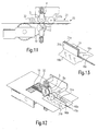
- Fig. 13
- an enlarged perspective view of a application device of Figures 11 and 12th
Nachfolgend wird unter Bezugnahme auf die Fig. 1 bis 6 eine Furnierzusammensetzmaschine 1 gemäß einem ersten Aufbau allgemein und hinsichtlich Ihrer Funktion beschrieben. Zur besseren Darstellbarkeit ist die Furnierzusammensetzmaschine 1 nur teilweise abgebildet. Die Furnierzusammensetzmaschine 1 umfasst in bekannter Weise eine Transporteinrichtung mit einer unteren Transportkette 19 und einer oberen Transportkette 21. Die untere Transportkette 19 wird über eine Welle 14 und Zahnräder 20a, 20b in Pfeilrichtung (vgl. Fig. 1) angetrieben. Die obere Transportkette 21 wird über eine Welle 12 und Zahnräder 22a, 22b in Pfeilrichtung (vgl. Fig. 1) angetrieben. Zwischen den beiden Transportketten 19, 21 werden in bekannter Weise wenigstens zwei nebeneinander angeordnete Furnierstreifen zu einer Heizeinrichtung (nicht dargestellt) transportiert, um die beiden Furnierstreifen miteinander zu verbinden.Hereinafter, a veneer assembling machine 1 according to a first structure will be described generally with respect to its function with reference to FIGS. 1 to 6. For ease of illustration, the veneer assembly machine 1 is shown only partially. The veneer assembly machine 1 comprises, in a known manner, a transport device with a
Die Furnierzusammensetzmaschine 1 umfasst weiter einen Einzug 2, welcher im Detail in den Fig. 4 bis 6 dargestellt ist. Der Einzug 2 umfasst einen zweiteiligen Anschlag 3, welcher aus einem ersten Anschlagelement 4 und einem zweiten Anschlagelement 7 gebildet ist, die sich an einem Kontaktpunkt K berühren. Wie insbesondere aus Fig. 4 ersichtlich ist, umfasst das erste Anschlagelement 4 eine Rolle 5 und ein Betätigungselement 6 und das zweite Anschlagelement 7 umfasst eine Wippe 8 und ein Betätigungselement 9. Das erste Anschlagelement 4 ist in Vertikalrichtung bewegbar und das zweite Anschlagelement 7 ist um eine Schwenkachse S schwenkbar. Die Wippe 8 weist eine zur Transportebene bzw. Transportrichtung X der Furnierstreifen geneigte Fläche 8a auf, welche im Wesentlichen U-förmig ausgebildet ist (vgl. Fig. 6).The veneer assembly machine 1 further comprises a
Weiterhin umfasst der Einzug 2 einen Riementrieb mit einem umlaufenden Riemen 10, einer auf einer Welle 12 gelagerten ersten Umlenkrolle 11 und einer auf der Welle 14 gelagerten zweiten Umlenkrolle 13. Der Riementrieb wird über die mit den Zahnrädern 20a, 20b gemeinsamen Welle 14 und der zweiten Umlenkrolle 13 mit der gleichen Geschwindigkeit wie die untere Transportkette 19 angetrieben.Furthermore, the
Weiter umfasst der Einzug 2 einen Einlegebereich 15, welcher insbesondere aus Fig. 3 erkennbar ist und benachbart zur ersten Umlenkrolle 11 angeordnet ist. Der Einlegebereich 15 umfasst eine nicht dargestellte Basisplatte, auf welche die Furnierstreifen 16 aufgelegt werden können. An der Basisplatte ist ein Trennsteg 18 vorgesehen, an welchen die beiden Furnierstreifen 16 in der in Fig. 3 gezeigten Weise angelegt werden. Weiterhin sind am Einlegebereich 15 zwei Zuführrollen 17a, 17b angeordnet, wobei jeweils eine der Zuführrollen rechts bzw. links vom Trennsteg 18 angeordnet ist. Wie aus Fig. 2 ersichtlich ist, sind die beiden Zuführrollen 17a, 17b leicht zum Trennsteg 18 schräg gestellt (um ca. 5° bis 10°), sodass beim Einschieben der Furnierstreifen 16 die Furnierstreifen durch die Zuführrollen 17a, 17b jeweils in Richtung des Trennsteges 18 gedrückt werden. Aufgrund ihrer Gewichtskraft üben die Zuführrollen 17a, 17b eine vorbestimmte Kraft auf die Furnierstreifen 16 aus. Es sei jedoch angemerkt, dass zur Unterstützung der Andruckkraft der Zuführrollen 17a, 17b zusätzlich noch eine Federkraft oder eine hydraulische oder pneumatische Kraft aufgebracht werden kann.Furthermore, the
Die Funktion des Einzugs 2 ist dabei wie folgt: Wie in Fig. 1 gezeigt, bildet der Anschlag 3 in der Ausgangsposition zwischen dem ersten Anschlagelement 4. und dem zweiten Anschlagelement 7 einen sich verjüngenden Anschlag. Wenn, wie in den Fig. 2 und 3 gezeigt, zwei an ihren seitlichen Stoßkanten zu verklebende Furnierstreifen 16 eingelegt werden, und von einem Bediener per Hand in Transportrichtung X vorgeschoben werden, unterstützen die beiden Zuführrollen 17a, 17b eine Bewegung der beiden Furnierstreifen 16 zueinander. Wenn die Furnierstreifen 16 weiter vorgeschoben werden, treffen sie auf die geneigte Fläche 8a der Wippe 8 und werden daran leicht etwas nach oben geführt.The function of the
Wie aus Fig. 1 ersichtlich ist, bildet der Anschlag 3 in seiner Ausgangsposition einen sich verjüngenden Anschlag, bestehend aus einem Mantelabschnitt der Rolle 5 und der geneigten Fläche 8a, sodass die beiden an dem Anschlag 3 anstoßenden Furnierstreifen nicht nur dort anliegen, sondern auch leicht zwischen dem ersten Anschlagelement 4 und dem zweiten Anschlagelement 7 geklemmt sind. Die erreichte Anschlagposition kann nun entweder von dem Bediener erkannt werden oder es ist ein Sensor, wie z.B. eine Lichtschranke oder ein Tastsensor, vorgesehen, welcher die Anschlagposition der beiden Furnierstreifen 16 erkennt. Im nächsten Schritt wird entweder von dem Bediener manuell oder durch Erkennen der Anschlagposition automatisch das zweite Anschlagelement 7 mittels des Betätigungselements 9 nach unten um die Schwenkachse S weggeschwenkt. Somit ist das zweite Anschlagelement 7 unterhalb des Riemens 10, genauer unterhalb des Obertrums des Riemens, angeordnet. Dadurch wird ein Durchlass zwischen der Rolle 5 des ersten Anschlagelements 4 und der Wippe 8 freigegeben, sodass die beiden Furnierstreifen mit dem ständig angetriebenen Riemen 10 in Kontakt kommen. Hierbei unterstützt die Gewichtskraft des ersten Anschlagelements 4 sowie das Betätigungselement 6 des ersten Anschlagelements 4 das Andrücken der Furnierstreifen 16 auf den Riemen 10, sodass beide Furnierstreifen 16 gleichmäßig mittels des Riemens 10 eingezogen werden.As can be seen from Fig. 1, the
Wie aus den Fig. 2 und 3 ersichtlich ist, ist der Riementrieb zwischen den Zahnrädern 20a, 20b der unteren Transportkette 19 angeordnet, sodass die durch den Riementrieb in Transportrichtung X geförderten Furnierstreifen 16 zwischen die untere und obere Transportkette 19, 21 vorgeschoben werden. Da der Riementrieb die gleiche Geschwindigkeit wie die Transportketten 19, 21 aufweist, werden die beiden Furnierstreifen ohne Positionsänderung von der Transporteinrichtung der Furnierzusammensetzmaschine weitertransportiert und der Heizvorrichtung zugeführt, sodass ein Verkleben der beiden Furnierstreifen 16 an ihrer Stoßkante möglich ist.As can be seen from FIGS. 2 and 3, the belt drive is arranged between the
Wie insbesondere aus den Fig. 3 und 6 ersichtlich ist, weist die geneigte Fläche 8a der Wippe 8 eine im Wesentlichen U-förmige Form auf, sodass jeweils ein freier Schenkel an einer Seite des Riemens 10 des Riementriebs angeordnet ist. Dadurch wird ein Verschwenken der Wippe 8 nach unten um die Schwenkachse 10 möglich. Weiterhin weist die Rolle 5 des ersten Anschlagelements 4 eine Breite auf, welche größer als die Breite des Riemens 10 ist, sodass die Rolle 5 zumindest noch teilweise im Bereich der Schenkel der U-förmigen, geneigten Fläche 8a der Wippe 8 angeordnet ist. Der Anschlag 3 des Einzuges 2 ist dabei am Riementrieb derart angeordnet, dass der Anschlag 3 etwas in Transportrichtung X von einem Scheitelpunkt R des Riementriebes am Einlegebereich 15 in Transportrichtung X versetzt ist. Genauer, wie insbesondere aus Fig. 4 ersichtlich ist, ist die Anschlagposition des Anschlags 3 (Kontaktpunkt K) derart gewählt, dass sie in einer Ebene senkrecht zur Transportrichtung X liegt, welche in Fig. 4 links von einer Linie durch die Drehachsen der Welle 12 der ersten Umlenkrolle 11 und der Rolle 5 liegt. Somit kann sichergestellt werden, dass nach dem Verschwenken der Wippe 8 die Furnierstreifen 16 mit einer vorbestimmten Länge auf dem Riemen 10 aufliegen und somit sicher vom Riementrieb zur Transporteinrichtung der Maschine 1 transportiert werden können.As can be seen in particular from FIGS. 3 and 6, the inclined surface 8a of the
Wenn die beiden eingelegten Furnierstreifen 16 vollständig am Anschlag 3 vorbeitransportiert wurden, wird die Wippe 8 mittels des Betätigungselements 9, welches z.B. pneumatisch oder hydraulisch betrieben werden kann, wieder in die in Fig. 1 bzw. 4 gezeigte Ausgangsposition zurückgebracht. Dies kann entweder manuell durch den Bediener geschehen oder ein Sensor erfasst, wenn die Furnierstreifen 16 an dem Anschlag 3 vorbeitransportiert worden sind. Somit können bei dem Einzug, unmittelbar nach dem Durchführen zweier Furnierstreifen 16 und einer Rückstellung des Anschlags 3, sofort wieder zwei neue Furnierstreifen 16 eingelegt und über den Riementrieb weitertransportiert werden, sodass die Taktzeiten für die Herstellung zusammengesetzter Furniere im Vergleich mit dem Stand der Technik signifikant reduziert werden können. Da der Riementrieb über die Transporteinrichtung der Furnierzusammensetzmaschine 1 mit angetrieben wird, ist kein separater Antrieb oder eine aufwendige Kupplung für den Einzug 2 notwendig. Dadurch können die Herstellungskosten für den Einzug sehr gering gehalten werden. Weiterhin kann dadurch Bauraum an der Furnierzusammensetzmaschine eingespart werden.When the two inserted veneer strips 16 have been completely transported past the
Für den Riemen 10 des Riementriebes kann ein Zahnriemen verwendet werden, welcher z.B. aus Kunststoff hergestellt ist. Weiterhin kann vorgesehen werden, dass, sobald die eingeführten Furnierstreifen 16 von den Transportketten 19, 21 weitertransportiert werden, das erste Anschlagelement 4 nach oben bewegt wird, um den Reibungswiderstand beim Zuführen der Furniere möglichst gering zu halten und das Einziehen der Furnierstreifen in die Transportketten nicht zu behindern. Dadurch werden auch Spannungen und Beulen in den Furnierstreifen verhindert. Weiterhin sei angemerkt, dass der Sensor, welcher die Anschlagsposition der Furnierstreifen 16 am Anschlag 3 detektiert, auch dazu verwendet werden kann, zu detektieren, wenn die Hinterkante der Furnierstreifen 16 den Sensor passiert, um dann den Anschlag 3 dann wieder in seine Ausgangsposition zu bringen.For the
Nachfolgend wird unter Bezugnahme auf die Fig. 7 bis 10 eine Furnierzusammensetzmaschine 1 gemäß einem zweiten Aufbau beschrieben. Dabei sind gleiche bzw. funktional gleiche Teile mit den gleichen Bezugszeichen wie im ersten beschriebenen Aufbau bezeichnet.Hereinafter, a veneer assembling machine 1 according to a second structure will be described with reference to Figs. The same or functionally identical parts are designated by the same reference numerals as in the first described construction.
Im Unterschied zum ersten Aufbau ist beim Einzug 2 gemäß dem zweiten Aufbau keine Wippe vorgesehen. Der Anschlag 3 des zweiten Aufbaus besteht aus einem ersten Anschlagelement 4 und einem zweiten Anschlagelement 27. Das zweite Anschlagelement 27 ist ein im Wesentlichen U-förmiges Element 28, welches an den beiden Schenkeln jeweils eine geneigte Fläche 28a aufweist. Die Fläche 28a ist dabei wieder relativ zur Transportrichtung X geneigt (vgl. Fig. 7). Weiter umfasst das zweite Anschlagelement 27 ein Betätigungselement 29. Wie durch die Pfeile in Fig. 7 und 9 angedeutet, wird das zweite Anschlagelement 27 nicht wie beim ersten Ausführungsbeispiel geschwenkt, sonder vertikal bewegt.In contrast to the first structure, no rocker is provided at the
Hierbei ist in Fig. 7 die Ausgangsstellung dargestellt, in welcher sich das erste Anschlagelement 4 und das zweite Anschlagelement des Anschlags 3 berühren und den sich verjüngenden Anschlag für die Furnierstreifen 16 bereitstellen. In Fig. 9 ist die zweite Position (Durchlassposition) des Anschlages 3 dargestellt, bei der das zweite Anschlagelement 27 nach unten in Vertikalrichtung abgesenkt wurde, sodass ein Durchlass zwischen dem ersten Anschlagelement 4 und dem zweiten Anschlagelement 27 gebildet ist. Die Furnierstreifen 16 werden durch Andrücken mittels des ersten Anschlagelements 4 auf den Riemen 10 eingezogen und zur Transporteinrichtung 19, 21 der Maschine transportiert, wobei die Rolle 5 ständig einen Druck auf die Furnierstreifen ausübt.Here, the starting position is shown in Fig. 7, in which touch the
Ansonsten entspricht die Funktion des Einzugs 2 gemäß dem zweiten Aufbau dem des ersten Aufbaus, sodass auf die dort gegebene Beschreibung verwiesen werden kann.Otherwise, the function of the
Nachfolgend wird unter Bezugnahme auf die Figuren 11 bis 13 ein Einlegebereich 15 mit einer erfindungsgemäßen Anlegevorrichtung 31 beschrieben. Die erfindungsgemäße Anlegevorrichtung 31 kann sowohl mit dem vorher beschriebenen ersten Aufbau der Furnierzusammensetzmaschine gemäß den Figuren 1 bis 6 als auch mit dem zweiten Aufbau der Furnierzusammensetzmaschine gemäß den Figuren 7 bis 10 anstelle des Trennsteges verwendet werden.In the following, with reference to FIGS. 11 to 13, an
Die erfindungsgemäße Anlegevorrichtung 31 ist, wie insbesondere aus Fig. 13 ersichtlich ist, im Schnitt im Wesentlichen U-förmig ausgestaltet. Dabei weist die Anlegevorrichtung 31 einen ersten wandförmigen Anschlag 31a und einen zweiten wandförmigen Anschlag 31b auf. Der Abstand der beiden Anschläge 31a und 31b ist dabei derart gewählt, dass ein Intarsienstreifen 16c zwischen den beiden Anschlägen 31a und 31b eingelegt und ausgerichtet werden kann.As can be seen in particular from FIG. 13, the
An den vom Intarsienstreifen 16c abgewandten Seiten der Wände der Anschläge 31a und 31b sind ein erster Furnierstreifen 16a bzw. ein zweiter Furnierstreifen 16b angelegt.A first veneer strip 16a and a
Es sei angemerkt, dass die Anlegevorrichtung 31 an der Furnierzusammensetzmaschine austauschbar angeordnet ist, um unterschiedliche Anlegevorrichtungen mit einem verschiedenen Abstand der wandförmigen Anschläge 31a und 31b auszutauschen. Dadurch können die Intarsienstreifen 16c mit unterschiedlichen Breiten verwendet werden.It should be noted that the applying
Wie aus den Figuren 11 und 12 ersichtlich ist, ist weiterhin eine Zusatzrolle 32 vorgesehen, welche nach der Rolle 5 angeordnet ist. Ferner ist an der Rolle 5 ein elastischer Ring 5a angeordnet. Der elastische Ring 5a ist beispielsweise aus einem Gummimaterial hergestellt. Der elastische Ring 5a hat die Aufgabe, Dickenunterschiede zwischen den Furnierstreifen 16a, 16b und dem Intarsienstreifen 16c auszugleichen. Die Zusatzrolle 32 ist vorgesehen, damit der mittlere, relativ schmale Intarsienstreifen 16c genügend weit transportiert wird, sodass er von den beiden benachbarten breiteren Furnierstreifen 16a und 16b mitgenommen werden kann. Für diese Aufgabe genügt es, wenn die Zusatzrolle 32 mit ihrem Eigengewicht auf den Intarsienstreifen 16c drückt. Dadurch wird der Intarsienstreifen 16c auf den umlaufenden Riemen 10 gedrückt und gemeinsam mit den Furnierstreifen 16a und 16b transportiert.As can be seen from Figures 11 and 12, an
Die Furnierstreifen werden derart in die Maschine eingelegt, dass zuerst ein erster breiter Furnierstreifen 16b, dann der Intarsienstreifen 16c und anschließend der zweite breite Furnierstreifen 16a in den Einzug der Maschine geschoben wird. Hierbei werden sie an der Anlegevorrichtung 31 ausgerichtet. Anschließend werden die Furnierstreifen wie vorher unter Bezugnahme auf die Figuren 1 bis 10 beschrieben, in die Furnierzusammensetzmaschine eingezogen.The veneer strips are inserted into the machine such that first a first
Durch die erfindungsgemäße Anlegevorrichtung 31 kann somit auf einfache und kostengünstige Weise ein Furnier mit einem integrierten Intarsienstreifen hergestellt werden. Da die Anlegevorrichtung 31 austauschbar vorgesehen ist, kann auch ein schnelles Umrüsten auf Intarsienstreifen unterschiedlicher Breite erfolgen. Es sei angemerkt, dass die Breite der Furnierstreifen 16a, 16b ca. 80 mm beträgt und der Intarsienstreifen 16c eine Breite von ca. 5 mm aufweist.By applying
Claims (15)
- Device for threading veneer strips (16) into a veneer assembling machine (1), comprising:- a belt drive comprising a belt (10) and arranged between an insertion area (15) for the veneer strips (16) and a transport device (19, 21) of the veneer assembling machine (1), and- a stop device (3), which forms a stop for the veneer strips (16) inserted,- the stop device (3) being spaced apart somewhat from a vertex (R) of the belt drive in the insertion region (15) in the transport direction (X) of the belt drive,- the stop device (3) comprising a first stop element (4), which is arranged above the belt (10), and a second stop element (7; 27), which is arranged at the side of the belt (10), and- it being possible for the second stop element (7; 27) to be moved to and fro between a first position, in which it is arranged somewhat above the belt (10) and provides the stop, and a second position, in which it is arranged underneath the belt (10) and provides a passage between the first and second stop element (3), and- a feeding device (31) being arranged in the insertion area (15) in order to feed and align veneer strips (16a), (16b), (16c), the feeding device (31) forming a first stop (31a) and a second stop (31b), in order to feed and align a veneer strip (16c) between the first and the second stop (31a), (31b).
- Device according to Claim 1, characterized in that the first stop (31a) and the second stop (31 b) are each formed as wall-like stops.
- Device according to one of the preceding claims, characterized in that the feeding device (31) has a substantially U-shaped configuration in section.
- Device according to one of the preceding claims, characterized in that the second stop element (7; 27) has an inclined surface (8a; 28a).
- Device according to one of the preceding claims, characterized in that the second stop element (7; 27) is arranged on both sides of the belt (10).
- Device according to Claim 5, characterized in that the second stop element (7) is formed as a U-shaped rocker (8) having inclined end surfaces (8a) or in that the second stop element (27) is formed as a U-shaped element (28) having inclined end surfaces (28a).
- Device according to one of the preceding claims, characterized in that the first stop element (4) has a roller (5).
- Device according to Claim 7, characterized in that the roller (5) is loaded with an additional force.
- Device according to Claim 7 or 8, characterized in that a contact point (K) of the stop device (3) lies in a plane perpendicular to the transport direction (X) through a pivot of the roller (5) or is spaced apart in the transport direction (X) from the plane perpendicular to the transport direction (X) through the pivot of the roller (5).
- Device according to one of Claims 7 to 9, characterized in that an elastic ring (5a) is arranged on the roller (5) in order to transport securely a veneer strip (16c) fed in between the first and second stop (31 a), (31 b).
- Device according to one of the preceding claims, characterized by an additional roller (32), which is arranged after the roller (5) in the transport direction (X), in order at least to press the veneer strip (16c) fed in between the first and second stop (31a), (31b) against the belt (10), in order to permit secure onward transport of the veneer strip (16c).
- Device according to one of the preceding claims, characterized by at least one feed roller (17a, 17b) which is set at an angle to the transport direction (X) of the veneers.
- Device according to one of the preceding claims, characterized in that the drive of the belt drive is provided via a shaft (14) of the transport device (19) of the veneer assembling machine.
- Device according to Claim 13, characterized in that a deflection roller (13) of the belt drive is arranged between two drive wheels (20a, 20b) of the transport device (19) on a common shaft (14).
- Device according to one of the preceding claims, characterized by a sensor in order to be able to register a stop position of the veneer strips (16) on the stop device (3) and/or to register complete threading of the veneer strips (16) into the veneer assembling machine (1).
Priority Applications (1)
| Application Number | Priority Date | Filing Date | Title |
|---|---|---|---|
| SI200530138T SI1776215T1 (en) | 2004-08-10 | 2005-05-24 | Device for drawing in veneer strips |
Applications Claiming Priority (2)
| Application Number | Priority Date | Filing Date | Title |
|---|---|---|---|
| DE102004038812A DE102004038812B3 (en) | 2004-08-10 | 2004-08-10 | Device for collecting veneer strips |
| PCT/EP2005/005616 WO2006015634A1 (en) | 2004-08-10 | 2005-05-24 | Device for drawing in veneer strips |
Publications (2)
| Publication Number | Publication Date |
|---|---|
| EP1776215A1 EP1776215A1 (en) | 2007-04-25 |
| EP1776215B1 true EP1776215B1 (en) | 2007-11-14 |
Family
ID=34967989
Family Applications (1)
| Application Number | Title | Priority Date | Filing Date |
|---|---|---|---|
| EP05742891A Not-in-force EP1776215B1 (en) | 2004-08-10 | 2005-05-24 | Device for drawing in veneer strips |
Country Status (6)
| Country | Link |
|---|---|
| EP (1) | EP1776215B1 (en) |
| CN (1) | CN100537162C (en) |
| AT (1) | ATE378159T1 (en) |
| DE (2) | DE102004038812B3 (en) |
| SI (1) | SI1776215T1 (en) |
| WO (1) | WO2006015634A1 (en) |
Families Citing this family (2)
| Publication number | Priority date | Publication date | Assignee | Title |
|---|---|---|---|---|
| WO2003100095A1 (en) | 2002-05-08 | 2003-12-04 | Arkray, Inc. | Method of detecting target nucleic acid |
| DE102016210552B3 (en) * | 2016-06-14 | 2017-08-31 | Heinrich Kuper Gmbh & Co Kg | Apparatus for assembling veneer strips into a sheet |
Family Cites Families (4)
| Publication number | Priority date | Publication date | Assignee | Title |
|---|---|---|---|---|
| IT1134488B (en) * | 1980-11-27 | 1986-08-13 | Mathias Manz | PROCEDURE AND EQUIPMENT FOR THE MUTUAL GLUING OF WOOD SHEETS OR WOOD VENEER ALONG A TRANSVERSAL LINE WITH RESPECT TO THE DIRECTION OF ADVANCE OF THE SAME |
| DE29717993U1 (en) * | 1997-10-13 | 1998-02-19 | Breusch Lieselotte | Transport and heating system for longitudinal veneer gluing machines |
| DE19809772C1 (en) * | 1998-03-06 | 1999-09-30 | Kurt Hoerger | Machine for assembling veneer sheets |
| DE10356217B3 (en) * | 2003-12-02 | 2005-04-14 | Heinrich Kuper Gmbh & Co Kg | Furniture veneer strip feed assembly has double feed belt linking insertion point to veneer application assembly |
-
2004
- 2004-08-10 DE DE102004038812A patent/DE102004038812B3/en not_active Expired - Fee Related
-
2005
- 2005-05-24 SI SI200530138T patent/SI1776215T1/en unknown
- 2005-05-24 DE DE502005002010T patent/DE502005002010D1/en not_active Expired - Fee Related
- 2005-05-24 AT AT05742891T patent/ATE378159T1/en not_active IP Right Cessation
- 2005-05-24 WO PCT/EP2005/005616 patent/WO2006015634A1/en active IP Right Grant
- 2005-05-24 CN CNB2005800269604A patent/CN100537162C/en not_active Expired - Fee Related
- 2005-05-24 EP EP05742891A patent/EP1776215B1/en not_active Not-in-force
Also Published As
| Publication number | Publication date |
|---|---|
| CN100537162C (en) | 2009-09-09 |
| CN101094752A (en) | 2007-12-26 |
| ATE378159T1 (en) | 2007-11-15 |
| EP1776215A1 (en) | 2007-04-25 |
| WO2006015634A1 (en) | 2006-02-16 |
| DE502005002010D1 (en) | 2007-12-27 |
| DE102004038812B3 (en) | 2006-02-09 |
| SI1776215T1 (en) | 2008-04-30 |
Similar Documents
| Publication | Publication Date | Title |
|---|---|---|
| EP2949609B1 (en) | Splicing device | |
| DE69727746T2 (en) | veneer Press | |
| EP2046566B1 (en) | Supply device | |
| DE10119508C1 (en) | Material guide system for splicing machines | |
| DE2606751B2 (en) | Method and device for joining sheets of veneer to one another | |
| EP2415700A2 (en) | Device for aligning a flat product | |
| EP3222569A1 (en) | Splice assembly | |
| DE10011207C2 (en) | Process and device for cross-gluing veneer strips | |
| AT518608B1 (en) | Kantenanleimvorrichtung | |
| EP0049016A1 (en) | Transport mechanism for webs of paper in accounting machines | |
| AT505211B1 (en) | DEVICE FOR PRODUCING WOODEN STRIKES MARKED BY RIVETED WEDGE PINE COMPOUNDS | |
| DE19506778A1 (en) | Process for the production of corrugated cardboard | |
| EP1776215B1 (en) | Device for drawing in veneer strips | |
| DE3224670C2 (en) | ||
| DE19747480C1 (en) | Machine cutting and fusing plastic plates | |
| EP1699608B1 (en) | Device for inserting a veneer band | |
| DE1627712A1 (en) | Device for assembling link chains | |
| EP2808281A2 (en) | Splicing device for splicing cord material | |
| DE19810574B4 (en) | Device for actuating presses in clamping devices for the assembly of furniture | |
| DE3419610A1 (en) | Method and apparatus for attaching cover sheets to blocks | |
| DE2523110A1 (en) | Veneer sheet production system with transport rollers - has counter pressure rollers and adhesive application systems | |
| EP1329403A2 (en) | Device for automatic aligning of cord bands being unwound | |
| EP1424211A1 (en) | Device for the production of bound printed products | |
| EP1029642B1 (en) | Veneer jointing machine | |
| DE3528041A1 (en) | MACHINE FOR STAMPING CARDBOARD |
Legal Events
| Date | Code | Title | Description |
|---|---|---|---|
| PUAI | Public reference made under article 153(3) epc to a published international application that has entered the european phase |
Free format text: ORIGINAL CODE: 0009012 |
|
| 17P | Request for examination filed |
Effective date: 20070205 |
|
| AK | Designated contracting states |
Kind code of ref document: A1 Designated state(s): AT BE BG CH CY CZ DE DK EE ES FI FR GB GR HU IE IS IT LI LT LU MC NL PL PT RO SE SI SK TR |
|
| GRAP | Despatch of communication of intention to grant a patent |
Free format text: ORIGINAL CODE: EPIDOSNIGR1 |
|
| DAX | Request for extension of the european patent (deleted) | ||
| GRAS | Grant fee paid |
Free format text: ORIGINAL CODE: EPIDOSNIGR3 |
|
| GRAA | (expected) grant |
Free format text: ORIGINAL CODE: 0009210 |
|
| AK | Designated contracting states |
Kind code of ref document: B1 Designated state(s): AT BE BG CH CY CZ DE DK EE ES FI FR GB GR HU IE IS IT LI LT LU MC NL PL PT RO SE SI SK TR |
|
| REG | Reference to a national code |
Ref country code: GB Ref legal event code: FG4D Free format text: NOT ENGLISH |
|
| REG | Reference to a national code |
Ref country code: CH Ref legal event code: EP |
|
| REG | Reference to a national code |
Ref country code: IE Ref legal event code: FG4D Free format text: LANGUAGE OF EP DOCUMENT: GERMAN |
|
| REF | Corresponds to: |
Ref document number: 502005002010 Country of ref document: DE Date of ref document: 20071227 Kind code of ref document: P |
|
| REG | Reference to a national code |
Ref country code: CH Ref legal event code: NV Representative=s name: KELLER & PARTNER PATENTANWAELTE AG WINTERTHUR |
|
| PG25 | Lapsed in a contracting state [announced via postgrant information from national office to epo] |
Ref country code: SE Free format text: LAPSE BECAUSE OF FAILURE TO SUBMIT A TRANSLATION OF THE DESCRIPTION OR TO PAY THE FEE WITHIN THE PRESCRIBED TIME-LIMIT Effective date: 20080214 Ref country code: NL Free format text: LAPSE BECAUSE OF FAILURE TO SUBMIT A TRANSLATION OF THE DESCRIPTION OR TO PAY THE FEE WITHIN THE PRESCRIBED TIME-LIMIT Effective date: 20071114 Ref country code: ES Free format text: LAPSE BECAUSE OF FAILURE TO SUBMIT A TRANSLATION OF THE DESCRIPTION OR TO PAY THE FEE WITHIN THE PRESCRIBED TIME-LIMIT Effective date: 20080225 |
|
| NLV1 | Nl: lapsed or annulled due to failure to fulfill the requirements of art. 29p and 29m of the patents act | ||
| PG25 | Lapsed in a contracting state [announced via postgrant information from national office to epo] |
Ref country code: IS Free format text: LAPSE BECAUSE OF FAILURE TO SUBMIT A TRANSLATION OF THE DESCRIPTION OR TO PAY THE FEE WITHIN THE PRESCRIBED TIME-LIMIT Effective date: 20080314 Ref country code: FI Free format text: LAPSE BECAUSE OF FAILURE TO SUBMIT A TRANSLATION OF THE DESCRIPTION OR TO PAY THE FEE WITHIN THE PRESCRIBED TIME-LIMIT Effective date: 20071114 Ref country code: LT Free format text: LAPSE BECAUSE OF FAILURE TO SUBMIT A TRANSLATION OF THE DESCRIPTION OR TO PAY THE FEE WITHIN THE PRESCRIBED TIME-LIMIT Effective date: 20071114 Ref country code: PL Free format text: LAPSE BECAUSE OF FAILURE TO SUBMIT A TRANSLATION OF THE DESCRIPTION OR TO PAY THE FEE WITHIN THE PRESCRIBED TIME-LIMIT Effective date: 20071114 Ref country code: BG Free format text: LAPSE BECAUSE OF FAILURE TO SUBMIT A TRANSLATION OF THE DESCRIPTION OR TO PAY THE FEE WITHIN THE PRESCRIBED TIME-LIMIT Effective date: 20080214 |
|
| GBV | Gb: ep patent (uk) treated as always having been void in accordance with gb section 77(7)/1977 [no translation filed] | ||
| PG25 | Lapsed in a contracting state [announced via postgrant information from national office to epo] |
Ref country code: DK Free format text: LAPSE BECAUSE OF FAILURE TO SUBMIT A TRANSLATION OF THE DESCRIPTION OR TO PAY THE FEE WITHIN THE PRESCRIBED TIME-LIMIT Effective date: 20071114 |
|
| EN | Fr: translation not filed | ||
| PG25 | Lapsed in a contracting state [announced via postgrant information from national office to epo] |
Ref country code: SK Free format text: LAPSE BECAUSE OF FAILURE TO SUBMIT A TRANSLATION OF THE DESCRIPTION OR TO PAY THE FEE WITHIN THE PRESCRIBED TIME-LIMIT Effective date: 20071114 Ref country code: RO Free format text: LAPSE BECAUSE OF FAILURE TO SUBMIT A TRANSLATION OF THE DESCRIPTION OR TO PAY THE FEE WITHIN THE PRESCRIBED TIME-LIMIT Effective date: 20071114 |
|
| PLBE | No opposition filed within time limit |
Free format text: ORIGINAL CODE: 0009261 |
|
| STAA | Information on the status of an ep patent application or granted ep patent |
Free format text: STATUS: NO OPPOSITION FILED WITHIN TIME LIMIT |
|
| PG25 | Lapsed in a contracting state [announced via postgrant information from national office to epo] |
Ref country code: PT Free format text: LAPSE BECAUSE OF FAILURE TO SUBMIT A TRANSLATION OF THE DESCRIPTION OR TO PAY THE FEE WITHIN THE PRESCRIBED TIME-LIMIT Effective date: 20080414 |
|
| REG | Reference to a national code |
Ref country code: IE Ref legal event code: FD4D |
|
| 26N | No opposition filed |
Effective date: 20080815 |
|
| PG25 | Lapsed in a contracting state [announced via postgrant information from national office to epo] |
Ref country code: FR Free format text: LAPSE BECAUSE OF FAILURE TO SUBMIT A TRANSLATION OF THE DESCRIPTION OR TO PAY THE FEE WITHIN THE PRESCRIBED TIME-LIMIT Effective date: 20080829 Ref country code: IE Free format text: LAPSE BECAUSE OF FAILURE TO SUBMIT A TRANSLATION OF THE DESCRIPTION OR TO PAY THE FEE WITHIN THE PRESCRIBED TIME-LIMIT Effective date: 20071114 |
|
| PG25 | Lapsed in a contracting state [announced via postgrant information from national office to epo] |
Ref country code: GB Free format text: LAPSE BECAUSE OF FAILURE TO SUBMIT A TRANSLATION OF THE DESCRIPTION OR TO PAY THE FEE WITHIN THE PRESCRIBED TIME-LIMIT Effective date: 20071114 |
|
| BERE | Be: lapsed |
Owner name: HEINRICH KUPER G.M.B.H. & CO KG Effective date: 20080531 |
|
| PG25 | Lapsed in a contracting state [announced via postgrant information from national office to epo] |
Ref country code: MC Free format text: LAPSE BECAUSE OF NON-PAYMENT OF DUE FEES Effective date: 20080531 |
|
| PG25 | Lapsed in a contracting state [announced via postgrant information from national office to epo] |
Ref country code: GR Free format text: LAPSE BECAUSE OF FAILURE TO SUBMIT A TRANSLATION OF THE DESCRIPTION OR TO PAY THE FEE WITHIN THE PRESCRIBED TIME-LIMIT Effective date: 20080215 |
|
| PG25 | Lapsed in a contracting state [announced via postgrant information from national office to epo] |
Ref country code: BE Free format text: LAPSE BECAUSE OF NON-PAYMENT OF DUE FEES Effective date: 20080531 |
|
| PG25 | Lapsed in a contracting state [announced via postgrant information from national office to epo] |
Ref country code: DE Free format text: LAPSE BECAUSE OF NON-PAYMENT OF DUE FEES Effective date: 20081202 Ref country code: EE Free format text: LAPSE BECAUSE OF FAILURE TO SUBMIT A TRANSLATION OF THE DESCRIPTION OR TO PAY THE FEE WITHIN THE PRESCRIBED TIME-LIMIT Effective date: 20071114 |
|
| PG25 | Lapsed in a contracting state [announced via postgrant information from national office to epo] |
Ref country code: CY Free format text: LAPSE BECAUSE OF FAILURE TO SUBMIT A TRANSLATION OF THE DESCRIPTION OR TO PAY THE FEE WITHIN THE PRESCRIBED TIME-LIMIT Effective date: 20071114 |
|
| PG25 | Lapsed in a contracting state [announced via postgrant information from national office to epo] |
Ref country code: AT Free format text: LAPSE BECAUSE OF NON-PAYMENT OF DUE FEES Effective date: 20080524 |
|
| PG25 | Lapsed in a contracting state [announced via postgrant information from national office to epo] |
Ref country code: HU Free format text: LAPSE BECAUSE OF FAILURE TO SUBMIT A TRANSLATION OF THE DESCRIPTION OR TO PAY THE FEE WITHIN THE PRESCRIBED TIME-LIMIT Effective date: 20080515 Ref country code: LU Free format text: LAPSE BECAUSE OF NON-PAYMENT OF DUE FEES Effective date: 20080524 |
|
| PG25 | Lapsed in a contracting state [announced via postgrant information from national office to epo] |
Ref country code: TR Free format text: LAPSE BECAUSE OF FAILURE TO SUBMIT A TRANSLATION OF THE DESCRIPTION OR TO PAY THE FEE WITHIN THE PRESCRIBED TIME-LIMIT Effective date: 20071114 |
|
| PGFP | Annual fee paid to national office [announced via postgrant information from national office to epo] |
Ref country code: CH Payment date: 20110525 Year of fee payment: 7 Ref country code: CZ Payment date: 20110520 Year of fee payment: 7 |
|
| PGFP | Annual fee paid to national office [announced via postgrant information from national office to epo] |
Ref country code: SI Payment date: 20110513 Year of fee payment: 7 |
|
| PGFP | Annual fee paid to national office [announced via postgrant information from national office to epo] |
Ref country code: IT Payment date: 20110527 Year of fee payment: 7 |
|
| REG | Reference to a national code |
Ref country code: CH Ref legal event code: PL |
|
| PG25 | Lapsed in a contracting state [announced via postgrant information from national office to epo] |
Ref country code: LI Free format text: LAPSE BECAUSE OF NON-PAYMENT OF DUE FEES Effective date: 20120531 Ref country code: CH Free format text: LAPSE BECAUSE OF NON-PAYMENT OF DUE FEES Effective date: 20120531 Ref country code: CZ Free format text: LAPSE BECAUSE OF NON-PAYMENT OF DUE FEES Effective date: 20120524 |
|
| PG25 | Lapsed in a contracting state [announced via postgrant information from national office to epo] |
Ref country code: IT Free format text: LAPSE BECAUSE OF NON-PAYMENT OF DUE FEES Effective date: 20120524 Ref country code: SI Free format text: LAPSE BECAUSE OF NON-PAYMENT OF DUE FEES Effective date: 20120525 |
|
| REG | Reference to a national code |
Ref country code: SI Ref legal event code: KO00 Effective date: 20130104 |