EP1329295A2 - Messer und Klemmvorrichtung zur Holzbearbeitung mit vielfachen Anwendungen - Google Patents
Messer und Klemmvorrichtung zur Holzbearbeitung mit vielfachen Anwendungen Download PDFInfo
- Publication number
- EP1329295A2 EP1329295A2 EP03445006A EP03445006A EP1329295A2 EP 1329295 A2 EP1329295 A2 EP 1329295A2 EP 03445006 A EP03445006 A EP 03445006A EP 03445006 A EP03445006 A EP 03445006A EP 1329295 A2 EP1329295 A2 EP 1329295A2
- Authority
- EP
- European Patent Office
- Prior art keywords
- clamping
- knife
- component
- features
- opposed
- Prior art date
- Legal status (The legal status is an assumption and is not a legal conclusion. Google has not performed a legal analysis and makes no representation as to the accuracy of the status listed.)
- Granted
Links
- 239000002023 wood Substances 0.000 title claims abstract description 60
- 238000000034 method Methods 0.000 claims description 14
- 239000000463 material Substances 0.000 claims description 8
- 239000002184 metal Substances 0.000 claims description 2
- 230000008901 benefit Effects 0.000 description 9
- 238000013461 design Methods 0.000 description 9
- 235000012431 wafers Nutrition 0.000 description 8
- 238000004519 manufacturing process Methods 0.000 description 6
- 238000013459 approach Methods 0.000 description 5
- 230000000712 assembly Effects 0.000 description 5
- 238000000429 assembly Methods 0.000 description 5
- 230000015572 biosynthetic process Effects 0.000 description 5
- 230000008859 change Effects 0.000 description 5
- 239000002245 particle Substances 0.000 description 5
- 238000012545 processing Methods 0.000 description 5
- 230000008569 process Effects 0.000 description 4
- 238000006073 displacement reaction Methods 0.000 description 3
- 238000007373 indentation Methods 0.000 description 3
- 230000007246 mechanism Effects 0.000 description 3
- 239000000047 product Substances 0.000 description 3
- 238000009434 installation Methods 0.000 description 2
- 239000011120 plywood Substances 0.000 description 2
- 230000002441 reversible effect Effects 0.000 description 2
- 230000009471 action Effects 0.000 description 1
- 238000005452 bending Methods 0.000 description 1
- 230000009286 beneficial effect Effects 0.000 description 1
- 239000006227 byproduct Substances 0.000 description 1
- 239000007795 chemical reaction product Substances 0.000 description 1
- 230000000593 degrading effect Effects 0.000 description 1
- 230000001419 dependent effect Effects 0.000 description 1
- 230000004807 localization Effects 0.000 description 1
- 238000012423 maintenance Methods 0.000 description 1
- 238000012986 modification Methods 0.000 description 1
- 230000004048 modification Effects 0.000 description 1
- 238000013021 overheating Methods 0.000 description 1
- 230000009467 reduction Effects 0.000 description 1
- 230000003252 repetitive effect Effects 0.000 description 1
- 230000000717 retained effect Effects 0.000 description 1
- 239000007787 solid Substances 0.000 description 1
- 230000009466 transformation Effects 0.000 description 1
Images

Classifications
-
- B—PERFORMING OPERATIONS; TRANSPORTING
- B27—WORKING OR PRESERVING WOOD OR SIMILAR MATERIAL; NAILING OR STAPLING MACHINES IN GENERAL
- B27G—ACCESSORY MACHINES OR APPARATUS FOR WORKING WOOD OR SIMILAR MATERIALS; TOOLS FOR WORKING WOOD OR SIMILAR MATERIALS; SAFETY DEVICES FOR WOOD WORKING MACHINES OR TOOLS
- B27G13/00—Cutter blocks; Other rotary cutting tools
- B27G13/08—Cutter blocks; Other rotary cutting tools in the shape of disc-like members; Wood-milling cutters
- B27G13/10—Securing the cutters, e.g. by clamping collars
-
- B—PERFORMING OPERATIONS; TRANSPORTING
- B27—WORKING OR PRESERVING WOOD OR SIMILAR MATERIAL; NAILING OR STAPLING MACHINES IN GENERAL
- B27G—ACCESSORY MACHINES OR APPARATUS FOR WORKING WOOD OR SIMILAR MATERIALS; TOOLS FOR WORKING WOOD OR SIMILAR MATERIALS; SAFETY DEVICES FOR WOOD WORKING MACHINES OR TOOLS
- B27G13/00—Cutter blocks; Other rotary cutting tools
- B27G13/02—Cutter blocks; Other rotary cutting tools in the shape of long arbors, i.e. cylinder cutting blocks
- B27G13/04—Securing the cutters by mechanical clamping means
-
- B—PERFORMING OPERATIONS; TRANSPORTING
- B27—WORKING OR PRESERVING WOOD OR SIMILAR MATERIAL; NAILING OR STAPLING MACHINES IN GENERAL
- B27L—REMOVING BARK OR VESTIGES OF BRANCHES; SPLITTING WOOD; MANUFACTURE OF VENEER, WOODEN STICKS, WOOD SHAVINGS, WOOD FIBRES OR WOOD POWDER
- B27L11/00—Manufacture of wood shavings, chips, powder, or the like; Tools therefor
- B27L11/005—Tools therefor
-
- Y—GENERAL TAGGING OF NEW TECHNOLOGICAL DEVELOPMENTS; GENERAL TAGGING OF CROSS-SECTIONAL TECHNOLOGIES SPANNING OVER SEVERAL SECTIONS OF THE IPC; TECHNICAL SUBJECTS COVERED BY FORMER USPC CROSS-REFERENCE ART COLLECTIONS [XRACs] AND DIGESTS
- Y10—TECHNICAL SUBJECTS COVERED BY FORMER USPC
- Y10T—TECHNICAL SUBJECTS COVERED BY FORMER US CLASSIFICATION
- Y10T29/00—Metal working
- Y10T29/49—Method of mechanical manufacture
- Y10T29/49826—Assembling or joining
- Y10T29/49947—Assembling or joining by applying separate fastener
- Y10T29/49963—Threaded fastener
-
- Y—GENERAL TAGGING OF NEW TECHNOLOGICAL DEVELOPMENTS; GENERAL TAGGING OF CROSS-SECTIONAL TECHNOLOGIES SPANNING OVER SEVERAL SECTIONS OF THE IPC; TECHNICAL SUBJECTS COVERED BY FORMER USPC CROSS-REFERENCE ART COLLECTIONS [XRACs] AND DIGESTS
- Y10—TECHNICAL SUBJECTS COVERED BY FORMER USPC
- Y10T—TECHNICAL SUBJECTS COVERED BY FORMER US CLASSIFICATION
- Y10T407/00—Cutters, for shaping
- Y10T407/19—Rotary cutting tool
- Y10T407/1906—Rotary cutting tool including holder [i.e., head] having seat for inserted tool
- Y10T407/1908—Face or end mill
- Y10T407/192—Face or end mill with separate means to fasten tool to holder
-
- Y—GENERAL TAGGING OF NEW TECHNOLOGICAL DEVELOPMENTS; GENERAL TAGGING OF CROSS-SECTIONAL TECHNOLOGIES SPANNING OVER SEVERAL SECTIONS OF THE IPC; TECHNICAL SUBJECTS COVERED BY FORMER USPC CROSS-REFERENCE ART COLLECTIONS [XRACs] AND DIGESTS
- Y10—TECHNICAL SUBJECTS COVERED BY FORMER USPC
- Y10T—TECHNICAL SUBJECTS COVERED BY FORMER US CLASSIFICATION
- Y10T407/00—Cutters, for shaping
- Y10T407/19—Rotary cutting tool
- Y10T407/1906—Rotary cutting tool including holder [i.e., head] having seat for inserted tool
- Y10T407/1908—Face or end mill
- Y10T407/1924—Specified tool shape
-
- Y—GENERAL TAGGING OF NEW TECHNOLOGICAL DEVELOPMENTS; GENERAL TAGGING OF CROSS-SECTIONAL TECHNOLOGIES SPANNING OVER SEVERAL SECTIONS OF THE IPC; TECHNICAL SUBJECTS COVERED BY FORMER USPC CROSS-REFERENCE ART COLLECTIONS [XRACs] AND DIGESTS
- Y10—TECHNICAL SUBJECTS COVERED BY FORMER USPC
- Y10T—TECHNICAL SUBJECTS COVERED BY FORMER US CLASSIFICATION
- Y10T407/00—Cutters, for shaping
- Y10T407/19—Rotary cutting tool
- Y10T407/1906—Rotary cutting tool including holder [i.e., head] having seat for inserted tool
- Y10T407/1934—Rotary cutting tool including holder [i.e., head] having seat for inserted tool with separate means to fasten tool to holder
- Y10T407/1938—Wedge clamp element
Definitions
- This invention relates generally to the forestry industry, and more specifically to the field of wood working machines of the type that are used to process wood to form chips or wafers for pulp or waferboard production, to form rough or finished lumber, or to form veneer for the production of plywood or laminated veneer lumber. Most particularly, this invention relates to wood working knives used in such machines, and to clamping assemblies to hold the knives in place.
- Wood is an important natural resource that is used in many of today's modern products. Within the forest industry, trees are harvested, cut into logs, and then subsequently undergo various processes to transform the logs into finished products. For example, in the pulp or oriented-strand board industries, the logs are passed through a machine which turns the solid log into chips or wafers. Such machines are typically referred to as chippers, which may be in a disc or a drum form, and waferizers or stranders, which can also take a number of forms.
- logs or semi-manufactured lumber it is common for logs or semi-manufactured lumber to be passed through machines which chip away the outside portions of the wood being processed to form rough lumber and a multitude of wood chips.
- Such machines are commonly referred to as chipper canters, chipper edgers and chipper slabbers, each of which can take a variety of different forms.
- this rough lumber is then processed by planers to yield finished lumber having a smooth cut surface and wood shavings as a by-product.
- veneer lathes Within the veneer industries, logs are turned on lathes to form veneer sheets that are subsequently used for the manufacturing of plywood or laminated veneer lumber. Such machines are commonly referred to as veneer lathes.
- planers, chippers, waferizers and other such wood processing machines are that they carry a number of knives mounted to a moving base, such as, for example, a rotating disc or drum.
- the wood being processed is moved into the path of the rotating knives and the blade contacts the wood at a depth and orientation that results in the formation of wood chips, shavings, wafers, or strands.
- chipper edgers, chipper canters, planers, or other similar wood finishing devices the knives are also appropriately positioned so as to result in the formation of a cut or planed surface on the wood being worked.
- veneer lathes however, the knife remains relatively stationary while the log, rotated about its axis, is engaged by the knife.
- the position of the cutting edge can be displaced from its desired and intended location relative to the wood being worked or important associate components within the machine such as anvils and guide plates.
- the position of the knife is adjusted in the clamping assembly each time, which is difficult to do accurately and is also time consuming, the performance achieved with the machine is degraded, sometimes to unacceptable levels.
- a precise positioning of the face or finishing knives relative to the wood being processed is a requirement for an accurate cut surface. Relatively small deviations in position can have a measurable impact on the quality of the finish achieved.
- Such a knife is shown, for example, in U.S. Patent Number 4,047,670 issued September 13, 1977 to Aktiebolaget Iggesunds Bruk.
- the knife is essentially a planar, elongate body with one cutting edge running along one side of the elongate body and a second cutting edge running along the other.
- the knife is mounted in a knife clamping assembly that is sized and shaped to secure the blade during operation and allow for easy and rapid knife changes.
- the knife is reversed and the second cutting edge is presented and used.
- the knife is disposed of and replaced with a new one having two more fresh cutting edges.
- Wood is not a homogeneous material. Sometimes, the wood will exert a greater force against one localized area of the cutting edge than against the remainder of the blade. The most common reason for this is that the cutting edge strikes a knot or some other irregularity in the wood. Further, with some arrangements, one or both ends of the knife may utilized to produce a side cut. This can add to the non-symmetric nature of the loads encountered by the knife.
- twisting may occur.
- the portion of the edge in contact with the irregularity bears a greater force. This difference in force along the length of the blade creates a torque on the knife which, if sufficiently large, can cause the knife to displace or twist in its mounting.
- a problem is to provide a knife and mounting assembly which is capable of handling such twisting forces.
- Another consideration is the relationship between the design of the knives and their mountings, and the quality of the wood product they produce. Specifically, the quality of the end product is dependent on the accuracy of position of the cutting edge relative to the machine achieved during the initial installation, and subsequently, the ability to maintain the position when subjected to load. The greater the accuracy of the knife position, in general, the better the quality of the wood working results.
- knives are inserted into the clamping assembly by hand. Under such circumstances, precise positioning may be difficult, simply because the required precision may be greater than is possible in a manual operation. In many cases, the knives are changed in situations that are physically awkward for the person changing the knife. Depending on the circumstances, the person may need to reach overhead or around cumbersome components to perform the change. This renders precise positioning even more difficult.
- a knife and a cooperating clamping assembly in which the knife can preferably be precisely positioned every time it is installed, even under difficult or awkward conditions.
- the knife and clamping assembly will each preferably be designed so as to reduce the risk of twisting or displacement during use. Most preferably, the knife and clamping assembly will be more easily adaptable to different loading and dimensional requirements, so that one design can be used in many applications. As well, what is preferred is a knife that can be easily reground to a certain degree for those applications in which limited regrinding may be advantageous.
- a wood working knife for use in a wood working machine, the knife comprising:
- a knife clamping assembly for clamping a wood working knife for use in a wood working machine
- the knife clamping assembly comprising a first clamping component for clamping a first clamping surface of the knife, and a second clamping component for clamping a second clamping surface of the knife, the first clamping component being sized and shaped to exert a clamping force on opposed clamping features of the knife such that, when the knife is clamped in the clamping assembly, a clamping force on the knife from the first clamping component is localized toward cutting edges of the knife and away from a middle section of the knife.
- a locking component for locking a clamping component to a machine
- the locking component comprising a locking component body, the locking component body having an externally threaded portion sized and shaped to engage the clamping component, a head having a shoulder sized and shaped to engage the machine, a through hole sized and shaped to permit a threaded fastener to pass therethrough, and driving features for driving the locking component body.
- a clamping assembly for clamping a knife in a wood working machine, the clamping assembly comprising:
- a method of sharpening a knife having opposed cutting edges comprising the steps of:
- a sharpening fixture for use in sharpening a knife having opposed cutting edges, the fixture comprising a supporting portion sized and shaped to support the knife by registering with a surface of the knife which comprised opposed clamping features and a substantially flat section therebetween.
- a wood working knife for use in a wood working machine, the knife comprising:
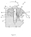
- FIG. 1 shows a knife clamping assembly indicated generally by reference numeral 10 clamping a knife 32.
- the knife clamping assembly 10 is mounted on a base 22 which may be any form of disc, drum, hub, or other base member, as may be used in chippers, chipper-canters, planers, waferizers, or other machines of the type used to process wood to form lumber, chips, veneer or wafers that includes knife clamping assemblies and knives.
- the clamping assembly 10 includes a fastener in the form of a bolt 12 having a shaft 14 and a head 16. A washer 13 abuts the head 16.
- the shaft 14 of the bolt 12 extends through a first clamping component which is preferably in the form of a rear clamping component 18 and a second clamping component which is preferably in the form of a front clamping component 20.
- the front clamping component 20 is secured to the base using a locking component which is in the form of a base bolt 17.
- the bolt 12 is shown as the preferred fastener of the clamping assembly 10, the present invention is not limited to using bolts, and comprehends that the clamping assembly 10 may be formed with other types of fastening mechanisms, such as a hydraulic or pneumatic mechanisms and the like. What is important is that the mechanism fastener functions such that, when actuated, it causes the first and second clamping components to clamp a knife therebetween securely enough for wood processing.
- the bolt 12 includes a threaded portion 24 which is threaded into bore 26 in the base 22.
- the bolt 12 can be either loosened or tightened as desired.
- the rear clamping component 18 is provided with a bore 28 therethrough, and the bolt 12 passes through the rear clamping component 18 via the bore 28.
- the front clamping component 20 is provided with a bore 30 and the bolt 12 is inserted through the front clamping component 20 through the bore 30.
- the bolt 12 is positioned so as to be clear of the knife 32.
- this embodiment does not require any holes in the knife 32 to accommodate a bolt or other fastener. It will be appreciated by those skilled in the art that making holes in the knife is both expensive and can weaken the knife, meaning that it must be made thicker to achieve the same strength. Thus, the absence of such holes in the preferred embodiment means the knife 32 is smaller and requires less material for its manufacture.
- the clamping assembly 10 is shown clamping a knife 32.
- the knife 32 comprises a knife body having opposed first and second cutting edges 34 and 36.
- the knife 32 has a first clamping surface which in this embodiment is a rear clamping surface 40.
- the knife 32 further includes a second clamping surface which in this embodiment is a front clamping surface 38.
- Each of the clamping surfaces 38, 40 extends between the cutting edges 34, 36.
- the front clamping component 20 is sized and shaped to clamp against the front clamping surface 38
- the rear clamping component 18 is sized and shaped to clamp the rear clamping surface 40.
- the base 22 rotates, thus moving the clamping assembly 10 and the knife 32 in a direction which is indicated by reference character A to drive the exposed cutting edge 34 into wood (not shown).
- "front” means positioned toward the direction of movement of the knife 32
- “back” means oriented or positioned away from that direction.
- the front clamping surface 38 of the knife 32 is positioned toward the direction of movement of the knife 32, while the rear clamping surface 40 is positioned away from that direction, or downstream.
- the front clamping component 20 is positioned toward the direction of movement of the knife 32, while the rear clamping component 18 is positioned away from that direction.
- the knife 32 As the knife 32, and in particular the exposed cutting edge 34, moves, it cuts into the wood being processed (not shown) which is appropriately positioned and/or maneuvered so as to be acted upon by the knife 32 at a depth and orientation that results in the formation of wood chips, shavings, wafers, strands, lumber or veneer.
- the drum, disc, hub or base member affixed thereto, which forms the base 22 will typically have a plurality of knives and related clamping assemblies distributed thereon at regular intervals. In this fashion, as rotation of the wood and/or knives occurs, the knives will move and act repeatedly on the wood so as to create the desired wood particles or so as to cut or plane the wood as desired.
- the front clamping surface 38 of the knife 32 is substantially flat, and the front clamping component 20 is sized and shaped to clamp against the substantially flat front clamping surface 38. Because the surface 38 is substantially flat, the leading portion 42 of the front clamping component 20 can be placed at a variety of locations along the front clamping surface 38 of the knife 32 without being constrained by protrusions and indentations in the front clamping surface of the knife 32. More specifically, when substantially flat, the front clamping surface 38 does not include any surface features which would limit the range of possible locations of the front clamping component 20 and its leading portion 42 by requiring corresponding features in the clamping component 20.
- leading portion 42 By contrast, having such surface features on the front clamping surface 38 would require that the leading portion 42 be positioned in a way to accommodate such features, in which case the number of possible locations for the leading portion 42 would be reduced. Further, to position the leading portion 42 near a protrusion or indentation, the front clamping component 20 would need to be specially designed to cooperate with the surface feature which is avoided by the instant invention. An altered location for the leading portion 42 is shown as 42' in Figure 1.
- the forward-most location of contact between the knife 32 and the front clamping component 20 on the underside of the knife can be varied depending upon the application to provide support further towards the exposed cutting edge as needed.
- the leading portion 42 of the front clamping component 20 can be located to clamp more or less of the underside of the knife 32 as needed for any given application, according to space available, stresses arising, wear restrictions and the like. This permits the knife and clamping assembly of the present invention to be used in a variety of applications (planers, disc chippers, etc.) without having to alter the knife profile. In this way one type of knife can be used in many applications.
- the substantially flat front clamping surface 38 allows a range of design positions for the leading portion 42. This provides a number of benefits. For example, it provides dimensional flexibility on the front side of the knife 32. Thus, if a particular application requires more room between the exposed cutting edge 34 and the leading portion 42 of the front clamping component 20, this can be easily accomplished through a change in the front clamping component 20. For example, a front clamping component can be conveniently used which has a the leading portion 42 well inward from the edge 34. Similarly, in applications where a close proximity of the leading portion 42 is required for the proper formation of the wood particles, such as may be required with waferizers or planers, this too can be achieved by a front clamping component which extends out towards the edge 34. Although in the preferred embodiment this change is accomplished through a change in the front clamping component 20 as described above, the present invention comprehends the use of an adjuster to alter the position of the leading portion 42.
- this configuration allows for the load bearing characteristics of the clamping assembly 10 and knife 32 to be adjusted according to the particular application.
- a front clamping component 20 with a leading portion 42 closer to the edge 34 (such as at 42') increases the amount of support given to the knife 32 by the clamping assembly 10. This helps secure the knife 32 against incidental loads directed to the top of the blade, for example.
- the substantially flat front clamping surface 38 therefore allows for more convenient deployment of such a front clamping component 20 such that both dimensional and strength requirements can be met for any given application.
- the flat front clamping surface also simplifies the design of the front clamping component 20, since the front clamping component 20 need only have a simple, substantially flat surface to bear on the flat front clamping surface 38.
- Other, more complex profiles for the front clamping component 20 could also be used with the substantially flat front clamping surface 38 and are comprehended by the present invention, provided adequate support was provided to the knife, but are less preferred for the reasons indicated above.
- the front clamping surface 38 of the knife 32 is preferably substantially flat, it is possible to regrind both of the edges 34, 36 with the removal of material from a single generally planar surface. This provides for an easy and efficient means to regrind the cutting edges of the knife 32 using simple traditional knife grinding equipment of the type generally present within wood processing facilities.
- both the edges 34, 36 can be sharpened simultaneously by applying a single grinder to surface 38. If, by contrast, there were a protrusion in the front clamping surface 38, then the edges 34, 36 could not be sharpened simultaneously using a single grinder, because the protrusion would interfere. Rather, it would be necessary to grind the portion of the front clamping surface adjacent to each of the cutting edges 34, 36 separately, so that regrinding the knife would take twice as long, and it would be more difficult to do evenly.
- a substantially flat middle section 52 be provided on the rear clamping surface 40 of the knife 32. It will be appreciated that this shape permits the knife 32 to be held on a flat magnetic table common for such machines by being laid on, and attached by, the substantially flat middle section 52. This permits for convenient regrinding of the knife 32.
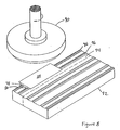
- Figure 8 shows a rotary grinder 90, preferably for grinding metal knives 32.
- One or more knifes 32 are supported on a sharpening fixture 92.
- the fixture 92 comprises a supporting portion 94 which is preferably sized and shaped to register with the clamping features 48, 50 of the knife 32.
- the supporting portion has support ridges 96 sized, shaped and positioned to register with the clamping features 48, 50 so as to inhibit lateral movement of the knife 32 during sharpening.
- the supporting portion 94 may also be sized and shaped to simultaneously register with the substantially flat middle section 52 if desired.
- the supporting portion 94 may be sized and shaped to register with the middle section 52 without registering with the clamping features 48, 50. This could be done if the middle section 52 protrudes further than any other part of the rear clamping surface.
- this alternative is not preferred, as it does not inhibit lateral movement during sharpening as effectively as the preferred embodiment. What is important is that the knife 32 be held so as to allow the edges 34, 36 to be simultaneously reground with one pass of a grinding wheel.
- the knife is resharpened.
- the knife is held by placing it on the supporting portion 94, preferably so that the ridges 96 register with the clamping features 48, 50.
- the fixture 92 is magnetized to act as a holder to hold the knife 32 in place.
- the cutting edges 34, 36 are simultaneously sharpened using the grinder 90, and the knife 32 is released from the table.
- the edges 34, 36 are reground simultaneously by removing material from the front clamping surface 38, which is substantially flat.
- material is removed from the surface 38.
- This grinding of the surface 38 sharpens the edges 34, 36 by shifting the surface 38 rearward until the edges 34, 36 are sharp once again.
- grinding the substantially flat front clamping surface 38 is preferred because it permits the edges 34, 36 to be simultaneously sharpened while maintaining the precise cutting angles of the edges (i.e. the angles at the intersection of the front clamping surface 38 and the rear clamping surface 40). This is because, by grinding the substantially flat front clamping surface 38 so as to shift the surface rearward, the cutting angles are retained even as the edges are sharpened.
- the position of the edges 34, 36 will be changed enough to affect the performance of the knife. However, some grinding is possible within the manufacturing tolerances of the machine.
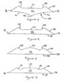
- the front clamping surface 38 is preferably substantially flat, the invention comprehends other shapes as well.
- the front clamping surface 38 comprises two gently concave surfaces 70, 72 meeting at a central line 74.
- the front clamping component 20 clamps against the surface 70, which is sized and shaped to engage the surface 70.
- this alternative shape for the front clamping component 20 and the front clamping surface 38 provides additional resistance to loads applied to the knife 32 in an direction along the plane of the knife 32. This improves the resistance of the knife to being displaced when mounted in the clamping assembly, whether inwardly in its mounting, by twisting or otherwise.
- the rear clamping surface 40 of the knife 32 has opposed clamping features 48, 50, separated by the middle section 52.
- the clamping features 48, 50 are sized and shaped such that, upon the knife 32 being inserted into the clamping assembly 10, clamping forces on the knife 32 from the rear clamping component 18 are localized towards the cutting edges 34, 36, and away from the middle section 52.
- the rear clamping component 18 is sized and shaped to register with, and exert a clamping force on, the opposed clamping features 48, 50.
- the localization of clamping forces toward the edges 34, 36 helps to securely clamp the knife 32.
- localizing the clamping forces towards the cutting edges allows the knife 32 and the clamping assembly 10 to more effectively resist twisting.
- twisting can occur when uneven cutting forces are applied along the length of the knife 32.
- Such an imbalance of forces creates a torque on the knife.
- a portion of the knife 32 can be urged out of the clamping assembly outwardly (i.e. in the direction of rotation A of the base 22) while the opposite portion is urged into the clamping assembly inwardly (i.e. in the direction opposite to rotation A).
- clamping forces which are localized toward the edges 34, 36 and away from the middle section 52 are better able, because of their spaced apart positioning, to resist a twisting torque on the knife 32. This is because, for any given clamping force, the capabilities to resist twisting are proportional to the distance between the clamping forces. Consequently, clamping forces, which are localized towards the extreme outer cutting edges, will most effectively counteract the twisting torque on the knife 32. It will be appreciated that, the further away the clamping force is localized from the middle of the knife 32, the more effectively twisting can be resisted. Thus, preferably, the majority of the clamping force will be localized toward the edges 34, 36 and away from the middle section 52. More preferably, at least 80 percent of the clamping force will be localized toward the edges 34, 36 and away from the middle section 52. Most preferably, all of the clamping force will be localized toward the edges 34, 36 and away from the middle section 52.
- the clamping features 48, 50 are concave hollows, or indentations, in the rear clamping surface 40.
- concave hollows has the advantage that the shape of the hollows results in the clamping force being applied in a direction that is substantially downward against the knife (i.e. orthogonal to the plane formed by edges 34, 36).
- Such an arrangement helps ensure that when the rear clamping component 18 registers with, and exerts a clamping force on, opposed clamping features 48, 50, there is no tendency for the clamping features to be wedged apart.
- bending stresses in the knife 32 are minimized.
- the use of concave hollows provides significant additional load carrying abilities in the form of resistance to twisting and the of displacement inward.
- clamping features need not be the concave hollows of the preferred embodiment.
- the clamping features take the form of opposing inclined surface sections 148, 150, which are oriented diagonally relative to the edges 34, 36.
- the clamping features may also be structured such that each clamping feature comprises two opposed surface sections inclined with respect to one another and moving further apart as they extend rearwardly. What is important is that the clamping features are sized and shaped to localize the clamping force toward the edges 34, 36 and away from the middle section 52.
- the middle section 52 be substantially flat in shape to permit for convenient regrinding of the knife 32. It will also be appreciated, however, that the middle section 52 need not have this preferred shape.
- An alternative shape for the middle surface 52 is shown at Figure 5 in which the profile gradually increases in thickness in the center section. This can be beneficial, for example, when resisting high cutting forces that otherwise result in a tendency to bend the knife under load.
- the opposed clamping features 48, 50 are also sized and shaped to act as locating features which direct the knife 32 to a predetermined position relative to the rear clamping component 18 when the knife is fastened in the clamping assembly 10.
- the clamping features 48, 50 have the preferred concave hollow shape, should the knife position be slightly displaced or askew as it is clamped, the rear clamping surface 18 will engage and exert a locating force on the sides of the concave hollows and push the knife 32 to the proper and preferred seating position. Once the knife 32 is in the correct position, the lateral or sideways forces against the clamping features balance substantially to zero, and the knife is positioned.
- the knife 32 will also be directed to the predetermined position by engaging the clamping features 148, 150 having the alternative diagonal shape described above and shown in Figures 3-5.
- the clamping features 148, 150 having the alternative diagonal shape described above and shown in Figures 3-5.
- what is required is to have two opposed inclined edges (whether curved or straight) which cause the knife to self center, or self locate, preferably relative to the rear clamping component 18, as the clamping assembly 10 is clamped onto the knife 32.
- clamping features act as locating features in the preferred embodiment
- the invention also comprehends locating features that are separate from the clamping features. What is important is that the locating features are sized and shaped to direct the knife 32 to a predetermined position when the knife 32 is fastened in the clamping assembly 10.
- the front clamping component 20 is fixedly attachable to the base 22 by the base bolt 17.
- the rear clamping component 18 is attachable to the base 22 via the bolt 12 so as to be movable between an open position and a clamped position.
- the rear clamping component 18 is moved to an open position by loosening the bolt 12.
- the knife 32 is placed between the clamping components 18, 20 and the rear clamping component 18 is moved to a clamped position by tightening the bolt 12.
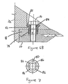
- FIGS 6A and 6B show an alternative clamping arrangement.
- this arrangement it is the rear clamping component 18 that is fixedly attachable to the base 22.
- the front clamping component 20 is movable between an open position and a clamped position.
- This arrangement is often referred to as “underside clamping", because the moving portion of the clamping assembly 10 is on the front or "underside” of the knife 32.
- underside clamping has the advantage of allowing the clamping assembly and the base 22 to more effectively support cutting loads generated by the impact between the knife 32 and wood.
- the rear clamping component 18 bears against the base 22 which is typically a rigid foundation component.
- the front clamping component is held in place by the bolt 12. With this arrangement the stiffness of the bolt has a significant influence on the overall load carrying capability of the knife assembly.
- underside clamping can often be done in less space than the clamping arrangement in Figure 1.
- underside clamping can be useful in situations where the knife 32 and the clamping assembly are located within a confined area.
- the assembly includes a locking component in the form of a locking screw 76 which engages with the rear clamping component 18.
- the locking screw 76 has an externally threaded portion 78 sized and shaped to secure the rear clamping component 18 to the base 22.
- the locking screw 76 also has a screw head 80 having a shoulder 82 sized and shaped to abut the bottom of a counterbore 81 in the base 22, and an internal through bore 84 sized and shaped to accommodate the bolt 12, as well as driving features for driving the screw 76.
- the driving features comprise a set of square corners 86 that run through the length of bore 84 of the screw 76 that are sized and shaped to be engaged by a driving tool 83 having a square drivable driving head 85.
- the driving features 86 are visible in Figure 7. It will be appreciated that the invention comprehends driving features and driving tools other than the preferred configurations described above. What is important is that the driving features permit the screw 76 to the driven so as to secure the rear clamping component 18 against the base 22.
- the rear clamping component 18 is engaged with the locking screw 76, installed into the counterbore 81 of base 22.
- the locking screw 76 is then tightened using the driving tool 83 in engagement with the driving features so as to secure the rear clamping component 18 against the base 22.
- the rear clamping component 18 is held in place by the shoulder 82 and the externally threaded portion 78
- the bolt 12 is then inserted through the screw 76, and it engages the threaded bore in the front clamping component 20.
- the front clamping component 20 is moved from an open position to a clamped position by turning the bolt 12.
- the bolt 12 is concentric with the screw 76.
- this configuration using the screw 76 has certain advantages.
- both the bolt 12 and the screw 76 are available to resist forces generated during cutting, giving the assembly greater stiffness and strength.
- the screw 76 protects the base 22 from contact with the head 16 of the bolt 12. Specifically, because the bolt 12 is activated often by being opened and closed, galling can occur on the base 22 if the head 16 of bolt 12 and the base 22 are in contact. However, in this configuration, the head 16 only contacts the screw 76 and shoulder 82 which prevents galling of the base 22. It will be appreciated that it is less expensive to replace the screw 76 when it is worn than it is to replace the section of the base 22 that becomes worn down by the bolt head 76.
- the locking screw also affords the advantage that the rear clamping component 18 can easily be secured to the base 22 from the rear or "topside". Often, in wood working machines space is limited such that it is not possible or desirable to use fasteners installed from the underside due to the lack of access to the base 22 from the front side of the machine.
Landscapes
- Life Sciences & Earth Sciences (AREA)
- Engineering & Computer Science (AREA)
- Mechanical Engineering (AREA)
- Wood Science & Technology (AREA)
- Forests & Forestry (AREA)
- Manufacturing & Machinery (AREA)
- Debarking, Splitting, And Disintegration Of Timber (AREA)
- Milling, Drilling, And Turning Of Wood (AREA)
- Finish Polishing, Edge Sharpening, And Grinding By Specific Grinding Devices (AREA)
Priority Applications (2)
| Application Number | Priority Date | Filing Date | Title |
|---|---|---|---|
| SI200332560T SI1329295T1 (en) | 2002-01-17 | 2003-01-17 | Woodworking blade and clamping set |
| EP17204133.7A EP3360658A1 (de) | 2002-01-17 | 2003-01-17 | Mehrzweck-holzbearbeitungsmesser |
Applications Claiming Priority (2)
| Application Number | Priority Date | Filing Date | Title |
|---|---|---|---|
| CA2368297A CA2368297C (en) | 2002-01-17 | 2002-01-17 | Multi-application wood working knife and clamping assembly |
| CA2368297 | 2002-01-17 |
Related Child Applications (1)
| Application Number | Title | Priority Date | Filing Date |
|---|---|---|---|
| EP17204133.7A Division EP3360658A1 (de) | 2002-01-17 | 2003-01-17 | Mehrzweck-holzbearbeitungsmesser |
Publications (3)
| Publication Number | Publication Date |
|---|---|
| EP1329295A2 true EP1329295A2 (de) | 2003-07-23 |
| EP1329295A3 EP1329295A3 (de) | 2007-08-29 |
| EP1329295B1 EP1329295B1 (de) | 2017-11-29 |
Family
ID=4171078
Family Applications (2)
| Application Number | Title | Priority Date | Filing Date |
|---|---|---|---|
| EP17204133.7A Withdrawn EP3360658A1 (de) | 2002-01-17 | 2003-01-17 | Mehrzweck-holzbearbeitungsmesser |
| EP03445006.4A Expired - Lifetime EP1329295B1 (de) | 2002-01-17 | 2003-01-17 | Messer zur Holzbearbeitung und Klemmvorrichtung für Messer zur Holzbearbeitung |
Family Applications Before (1)
| Application Number | Title | Priority Date | Filing Date |
|---|---|---|---|
| EP17204133.7A Withdrawn EP3360658A1 (de) | 2002-01-17 | 2003-01-17 | Mehrzweck-holzbearbeitungsmesser |
Country Status (5)
| Country | Link |
|---|---|
| US (5) | US7159626B2 (de) |
| EP (2) | EP3360658A1 (de) |
| CA (3) | CA2686670C (de) |
| DE (1) | DE20321875U1 (de) |
| SI (1) | SI1329295T1 (de) |
Cited By (8)
| Publication number | Priority date | Publication date | Assignee | Title |
|---|---|---|---|---|
| US20040168745A1 (en) * | 2002-10-25 | 2004-09-02 | Stager Bradley R. | Ring slicer with easily removable knife and knife assembly |
| US7069969B2 (en) | 2003-09-25 | 2006-07-04 | Key Knife, Inc. | Wood cutting knife assembly providing improved knife stability |
| WO2006073362A1 (en) * | 2005-01-07 | 2006-07-13 | Iggesund Tools Ab | Clamping assembly for woodworking knife |
| US7140408B1 (en) | 2006-02-03 | 2006-11-28 | Key Knife, Inc. | Knife assembly and chipping knife therefor |
| WO2008063201A1 (en) * | 2006-11-22 | 2008-05-29 | Key Knife, Inc. | Knife assembly and chipping knife therefor |
| WO2008085112A1 (en) * | 2007-01-12 | 2008-07-17 | Iggesund Tools Ab | Chipper knife and method of manufacturing a chipper knife |
| WO2008085111A1 (en) * | 2007-01-12 | 2008-07-17 | Iggesund Tools Ab | Chipper knife and method of manufacturing a chipper knife |
| CN101823219A (zh) * | 2010-04-08 | 2010-09-08 | 薛凤明 | 自为基准刀片刃口倒棱装置 |
Families Citing this family (23)
| Publication number | Priority date | Publication date | Assignee | Title |
|---|---|---|---|---|
| CA2686670C (en) * | 2002-01-17 | 2012-09-25 | Iggesund Tools Ab | Multi-application wood working knife and clamping assembly |
| KR101085683B1 (ko) | 2004-03-10 | 2011-11-22 | 신세스 게엠바하 | 길이방향으로 조립되는 구성요소 간의 상호 위치고정을위한 장치 |
| US8281826B2 (en) * | 2007-10-22 | 2012-10-09 | Iggesund Tools Ab | Sharp edged knife stop |
| SE531637C2 (sv) * | 2007-10-24 | 2009-06-16 | Iggesund Tools Ab | Huggkniv, huggknivsenhet samt ett förfarande för montering av en huggkniv |
| US20090200411A1 (en) * | 2008-02-07 | 2009-08-13 | Stager Bradley R | Chipping knife and assembly |
| CN102418733B (zh) * | 2010-09-28 | 2013-08-07 | 富泰华工业(深圳)有限公司 | 高度调整机构及使用其对电子装置进行组装的组装方法 |
| DE202010014029U1 (de) * | 2010-10-08 | 2012-01-09 | Doppstadt Familienholding Gmbh | Schlegel mit geteilter Schlegelspitze |
| US20140216605A1 (en) * | 2011-04-22 | 2014-08-07 | Stuart Batty | Negative rake scraper |
| CN105479527B (zh) * | 2011-05-23 | 2018-11-13 | 罗斯约私人有限公司 | 追踪图像的方法和设备、刀具切割系统和计算机程序产品 |
| USD705274S1 (en) * | 2011-08-30 | 2014-05-20 | Andritz Iggesund Tools Ab | Knife clamp assembly |
| USD694725S1 (en) * | 2011-10-28 | 2013-12-03 | Arielle Marq Incorporated | Magnetic apparatus for securing an object |
| US9168672B2 (en) | 2012-07-24 | 2015-10-27 | Key Knife, Inc. | Knife with disposable inserts |
| US9375723B2 (en) | 2013-04-29 | 2016-06-28 | Vermeer Manufacturing Company | Cutter assembly and adjustable cutter for use in comminuting apparatus |
| US9370776B2 (en) | 2013-04-29 | 2016-06-21 | Vermeer Manufacturing Company | Mounting block for attaching a reducing element to a rotary drum |
| CN103692522A (zh) * | 2013-12-24 | 2014-04-02 | 徐存然 | 一种木材削片机的刀盘固定装置 |
| USD772316S1 (en) * | 2015-04-01 | 2016-11-22 | Zenith Cutter, Inc. | Knife assembly |
| USD772317S1 (en) * | 2015-04-01 | 2016-11-22 | Zenith Cutter, Inc. | Knife insert |
| US10357776B2 (en) * | 2016-09-09 | 2019-07-23 | Comcorp, Inc. | Impact cutter blade and holder system and method |
| EP3527342A1 (de) * | 2018-02-20 | 2019-08-21 | Fam | Messeranordnung und damit ausgestattetes schneidsystem |
| CN111319103A (zh) * | 2020-03-13 | 2020-06-23 | 重庆德沃木制品加工有限公司 | 一种家具板生产方法 |
| CN114290449A (zh) * | 2020-05-31 | 2022-04-08 | 日照亚创电子科技有限公司 | 一种木材加工用直边机及其使用方法 |
| CA216417S (en) * | 2020-07-13 | 2022-10-18 | Andritz Ab | Wood chipper knife |
| CN112720731B (zh) * | 2020-12-28 | 2022-08-16 | 江门市吉思美家具有限公司 | 一种多功能数控木工机床 |
Citations (2)
| Publication number | Priority date | Publication date | Assignee | Title |
|---|---|---|---|---|
| US4047670A (en) | 1973-10-25 | 1977-09-13 | Aktiebolaget Iggesunds Bruk | Knife device for a chopper |
| US6058989A (en) | 1998-09-11 | 2000-05-09 | Iggesund Tools Ab | Self aligning knife clamping assemblies and machines incorporating the same |
Family Cites Families (106)
| Publication number | Priority date | Publication date | Assignee | Title |
|---|---|---|---|---|
| CA707966A (en) | 1965-04-20 | B. Farndale Edward | Boring bar cutter | |
| CA706587A (en) | 1965-03-30 | G. Lundgren Evert | Tool holder | |
| US2463859A (en) * | 1945-07-25 | 1949-03-08 | Boots Aircraft Nut Corp | Threaded locking device |
| US2830635A (en) * | 1954-07-20 | 1958-04-15 | Harold C Thorstens | Self-locking set screw having frangible intermediate portion |
| US3977447A (en) | 1969-08-11 | 1976-08-31 | Lionel Pease | Harvester chipper machine |
| US3757839A (en) * | 1969-12-08 | 1973-09-11 | Nicholson Mfg Co | Chipper bit and holder |
| US3661192A (en) * | 1969-12-08 | 1972-05-09 | Nicholson Mfg Co | Peripheral chipper for round log sections |
| CA994650A (en) | 1971-05-10 | 1976-08-10 | Nicholson Manufacturing Company | Chipper |
| CA981894A (en) | 1971-05-10 | 1976-01-20 | Stanley D. Vanek | Chipper bit and holder |
| US3754309A (en) | 1972-01-28 | 1973-08-28 | Kennametal Inc | Cutting insert and clamping arrangement therefor |
| SE361274B (de) | 1972-03-16 | 1973-10-29 | Sandvik Ab | |
| US3907016A (en) * | 1972-05-02 | 1975-09-23 | Nicholson Mfg Co | Peripheral chipper cutting bit holder |
| SE405081B (sv) | 1974-02-07 | 1978-11-20 | Sandvik Ab | Kniv for tyngre bearbetning |
| US3934320A (en) | 1974-11-01 | 1976-01-27 | Kennametal Inc. | Grooving and cut off tool |
| CA1015937A (en) | 1975-04-10 | 1977-08-23 | Josef D. Grungras | Machine tool bit and holder |
| US4054977A (en) | 1976-05-03 | 1977-10-25 | Giddings & Lewis, Inc. | Block type cutting tool with positive clamp for insert blades |
| SE401903B (sv) | 1976-12-31 | 1978-06-05 | Karlstad Mekaniska Ab | Anordning vid fliskuggningsmaskiner av skivtyp |
| FR2378972A1 (fr) * | 1977-01-28 | 1978-08-25 | Spit Soc Prospect Inv Techn | Perfectionnement aux chevilles a noyau d'expansion |
| US4082127A (en) | 1977-04-22 | 1978-04-04 | Miller Frederick L B | Knife holder in log slabbing chipper |
| FI781609A7 (fi) | 1978-05-22 | 1979-11-23 | Valo Antti T | Bett foer en skaeranordning foer en flishack eller liknande traereduceringsmaskin |
| US4269244A (en) | 1978-07-13 | 1981-05-26 | Schurman Machine Works, Inc. | Rotary chipping head |
| SE448842B (sv) | 1979-12-12 | 1987-03-23 | Iggesunds Bruk Ab | Forfarande for framstellning av en stockstyrningsyta |
| DE3102065C2 (de) | 1980-03-08 | 1986-01-09 | Eugen Lutz GmbH u. Co Maschinenfabrik, 7130 Mühlacker | Messerhalterung für Messerwellen oder Messerköpfe |
| FR2477945A1 (fr) | 1980-03-14 | 1981-09-18 | Creusot Loire | Dispositif de coupe pour une coupeuse a bois produisant des copeaux |
| DE3202742A1 (de) * | 1982-01-28 | 1983-08-04 | Udo 6200 Wiesbaden Rieser | Messerschaerfer |
| US4423758A (en) | 1982-02-25 | 1984-01-03 | Murray Machinery, Inc. | Disc type wood chipper knife having position adjusting serrations |
| US4694995B1 (en) | 1982-04-21 | 2000-11-14 | Iggesund Turnknife Systems Inc | Device in connection with choppers |
| CH650431A5 (fr) | 1983-02-09 | 1985-07-31 | Samvaz Sa | Outil de coupe a couteaux amovibles. |
| US4503893A (en) | 1983-05-25 | 1985-03-12 | Murray Machinery, Inc. | Disc type wood chipper knife having positioning serrations and intermediate land therebetween |
| US4569380A (en) * | 1983-09-16 | 1986-02-11 | Arasmith Stanley D | Wood chipping knife and apparatus using same |
| CH658424A5 (en) * | 1984-09-13 | 1986-11-14 | Samvaz Sa | Cutting tool with removable cutters |
| US4695208A (en) | 1985-11-14 | 1987-09-22 | Yankoff Gerald K | Tool holder |
| US4669516A (en) | 1985-11-18 | 1987-06-02 | Duratech, Inc. | V-shaped chipper knife |
| DE3636618A1 (de) | 1986-10-28 | 1988-05-05 | Babcock Bsh Ag | Messerwelle |
| US4771718A (en) | 1987-06-24 | 1988-09-20 | Commercial Knife, Inc. | Chipper disc and knife assembly |
| US4784337A (en) | 1987-09-21 | 1988-11-15 | Carthage Machine Company, Div. Of Industrial General Corporation | Reversible knife assembly for wood chipper |
| US4946319A (en) | 1988-08-12 | 1990-08-07 | Kennametal Inc. | Cutting insert and clamping arrangement therefor |
| AU627779B2 (en) | 1988-10-20 | 1992-09-03 | A.E. Bishop & Associates Pty Limited | Rotary slot cutting tools and inserts therefor |
| US4911939A (en) * | 1988-10-21 | 1990-03-27 | Nabisco Brands, Inc. | Shelf-stable microwavable cookie dough |
| DE3843466A1 (de) * | 1988-12-23 | 1990-06-28 | Bosch Gmbh Robert | Zerspanungsmaschine |
| US4887772A (en) | 1989-02-10 | 1989-12-19 | Carthage Machine Co., Div. Of Industrial General Corp. | Cassette knife for chipper |
| NL8902275A (nl) | 1989-09-12 | 1991-04-02 | Duracarb Bv | Beitelhouder en een beitel van een verspanende machine. |
| US5133394A (en) * | 1989-11-17 | 1992-07-28 | Peter Landtwing | Quick-clamping device operated by centrifugal force, for planing blades |
| DE59010420D1 (de) | 1989-11-17 | 1996-08-22 | Peter Frey Consulting | Fliehkraftbetätigte Schnellspannvorrichtung für Hobelmesser |
| AT397629B (de) | 1990-02-05 | 1994-05-25 | Boehler Ybbstalwerke | Einrichtung zur messerbefestigung an umlaufenden hackscheiben von (holzspan)-hackmaschinen sowie (einweg-)hackmesser hiefür |
| US4977939A (en) | 1990-05-07 | 1990-12-18 | Carthage Machine Company | Knife assembly for chipper |
| US4997018A (en) | 1990-06-25 | 1991-03-05 | Commercial Knife, Inc. | Mounted knife system |
| US5129437A (en) | 1991-06-27 | 1992-07-14 | Carthage Machine Company | Wood chipper knife holder with replaceable wearplate |
| US5288191A (en) * | 1991-08-26 | 1994-02-22 | Ewald Witte Gmbh & Co. Kg | Device for the clamping attachment of spaced structural parts |
| US5146963A (en) | 1991-11-04 | 1992-09-15 | Commercial Knife, Inc. | Chipping device |
| DE4204077C1 (de) | 1992-02-12 | 1992-09-17 | Inter-Wood-Maschinen Gmbh & Co Kg, 8923 Lechbruck, De | |
| DE4219447A1 (de) | 1992-06-13 | 1992-11-05 | Inter Wood Maschinen | Messerhalterung fuer das schneidwerkzeug einer holzzerspanungsmaschine |
| US5582535A (en) * | 1992-06-18 | 1996-12-10 | Edgecraft Corporation | Method and apparatus for knife and blade sharpening |
| AT398401B (de) | 1992-08-26 | 1994-12-27 | Boehler Ybbstalwerke | Wendemesser, insbesondere wendehobelmesser |
| FI90322C (fi) | 1992-11-18 | 1994-01-25 | Andritz Patentverwaltung | Menetelmä ja laite kiekkohakun terän vaihtamiseksi |
| US5271442B1 (en) | 1993-02-19 | 1996-05-07 | Commercial Knife Inc | Knife with clamp package mounting knife |
| US5271440A (en) * | 1993-02-24 | 1993-12-21 | Pacific/Hoe Saw And Knife Company | Chipper disc assembly having extended-life regrindable disposable knives |
| US5409047A (en) * | 1993-05-10 | 1995-04-25 | Jorgensen; Ray B. | Chipper knife |
| US5564967A (en) | 1993-05-10 | 1996-10-15 | Jorgensen; Ray B. | Method for sharpening a chipper knife |
| FI933131A0 (fi) | 1993-07-08 | 1993-07-08 | Sunds Defibrator Woodhandling | Skaersystem, skaer, styrdel och fyllningsdel foer maskin anvaend i flishuggning samt foerfarande foer bytning av skaer |
| US5333659A (en) | 1993-07-21 | 1994-08-02 | Key Knife, Inc. | Knife holder |
| US5348064A (en) | 1993-09-07 | 1994-09-20 | Carthage Machine Company | Reversible knife holder for chipper |
| US5469902A (en) | 1993-09-13 | 1995-11-28 | American Knife, Inc. | Chipper knife and knife holder assembly |
| AT400478B (de) * | 1993-09-30 | 1996-01-25 | Ideal Standard | Mit einem gewinde versehener bauteil mit einem werkzeugansatzbereich |
| SE504431C2 (sv) | 1994-06-29 | 1997-02-10 | Iggesund Tools Ab | Knivanordning |
| US5501256A (en) | 1994-07-18 | 1996-03-26 | U.S. Natural Resources, Inc. | Chipper knife |
| US5485873A (en) | 1994-08-09 | 1996-01-23 | Cae Machinery Ltd. | Knife clamping system |
| US5439039A (en) * | 1994-08-30 | 1995-08-08 | Pacific Saw And Knife Company | Slabber with fixed counterknife and adjustable knife and clamp |
| US5511597A (en) | 1995-01-06 | 1996-04-30 | Key Knife, Inc. | Slabbing chipper with replaceable knives and wear plate |
| US5575320A (en) | 1995-01-11 | 1996-11-19 | Les Ateliers Benoit Allard, Inc. | Cutting tool assembly for a rotatable chip forming head |
| FI950885A0 (fi) | 1995-02-27 | 1995-02-27 | Sunds Defibrator Woodhandling | Foerfarande foer reglering av flislaengd, skivhugg och skivhuggs skiva |
| US5505239A (en) | 1995-03-14 | 1996-04-09 | U.S. Natural Resources | Blade arrangement and blade holder for chipper |
| CA2214413A1 (en) | 1995-03-15 | 1996-09-19 | Sunds Defibrator Woodhandling Oy | A method of increasing the strength of a blade, and a blade |
| DE29506458U1 (de) | 1995-04-15 | 1995-07-06 | Gebr. Leitz GmbH & Co, 73447 Oberkochen | Messerkopf, insbesondere Hobelmesserkopf |
| FI96288C (fi) | 1995-04-20 | 1996-06-10 | Kone Wood Oy | Laite terän kiinnittämiseksi hakun pyöritettävään kiekkoon |
| US5617908A (en) | 1995-06-07 | 1997-04-08 | Key Knife, Inc. | Chipping cutter head including end cutting knives |
| US5613538A (en) | 1995-10-18 | 1997-03-25 | Denis Comact Inc. | Knife holder for timber shaping and chip producing head |
| US5697929A (en) * | 1995-10-18 | 1997-12-16 | Cross Medical Products, Inc. | Self-limiting set screw for use with spinal implant systems |
| US5623977A (en) | 1995-12-11 | 1997-04-29 | U.S. Natural Resources, Inc. | Chipper blade for chipper having radiused cutting edge |
| FI99240C (fi) | 1996-01-22 | 1997-12-10 | Sunds Defibrator Woodhandling | Menetelmä kiekkohakkurin terän alustan kestävyyden lisäämiseksi, kiekkohakkurin terän alusta ja kiekkohakkuri |
| FI103772B1 (fi) | 1996-07-08 | 1999-09-30 | Kauko Rautio | Teräpala puuntyöstökonetta varten |
| FI99281C (fi) | 1996-07-10 | 1998-05-25 | Sunds Defibrator Woodhandling | Kiekkohakkurin teräkiekkojärjestely ja kulutuslevyn saranalista |
| FR2750907B1 (fr) | 1996-07-12 | 1998-09-18 | Technogenia | Couteau d'ecorcage, et procede pour sa realisation |
| CA2184228C (en) | 1996-08-27 | 1999-03-23 | Ray B. Jorgensen | Method for sharpening a chipper knife |
| US5709255A (en) | 1996-10-18 | 1998-01-20 | Key Knife, Inc. | Chipper with detachable facing knives |
| US5919826A (en) * | 1996-10-24 | 1999-07-06 | Algos Pharmaceutical Corporation | Method of alleviating pain |
| US6224596B1 (en) * | 1997-01-06 | 2001-05-01 | Roger P. Jackson | Set screw for use with osteosynthesis apparatus |
| US5820042A (en) | 1997-06-17 | 1998-10-13 | Wood Technology, Inc. | Wood chipper rotor head knife holder and knife assembly |
| US5816301A (en) | 1997-07-30 | 1998-10-06 | Key Knife, Inc. | Knife supporting structure |
| US5819826A (en) | 1997-10-23 | 1998-10-13 | Key Knife, Inc. | Chip cutting knife with spaced deflector ridges |
| US5996655A (en) | 1997-12-11 | 1999-12-07 | Cae Machinery Ltd. | Pivoting knife clamp |
| DE19807111A1 (de) | 1998-02-20 | 1999-08-26 | Will E C H Gmbh & Co | Messertrommel für Maschinen zum Querschneiden von Materialbahnen |
| US6974290B2 (en) * | 1998-06-26 | 2005-12-13 | Dynamic Marketing Group Limited | Connecting assembly for joining two panels and mounting the joined panels on a support |
| DE19835725B4 (de) * | 1998-08-07 | 2016-08-04 | Robert Bosch Gmbh | Hobelkopf |
| US5937923A (en) | 1998-08-10 | 1999-08-17 | Beloit Technologies, Inc. | Chip slicer |
| US5979522A (en) | 1998-11-18 | 1999-11-09 | Key Knife, Inc. | Knife holder for a chipper disc |
| DE19858740C1 (de) | 1998-12-18 | 2000-06-08 | Paul Guels Maschinenbau | Messerwerkzeugkopf sowie Messer und Messerhalter hierfür |
| CA2275449A1 (en) * | 1999-06-18 | 2000-12-18 | Michael Lindsay Capp | A log chipping head |
| US6357953B1 (en) * | 1999-12-16 | 2002-03-19 | General Motors Corporation | Tolerance compensation apparatus |
| CA2307408A1 (en) | 2000-05-03 | 2001-11-03 | Tembec Industries Inc. | Improved chipper canter head and knife mounting |
| US6968879B2 (en) | 2001-07-30 | 2005-11-29 | Key Knife, Inc. | Knife and apparatus for clamping a knife |
| US6591878B2 (en) | 2001-07-18 | 2003-07-15 | Key Knife, Inc. | Method and apparatus for clamping a knife |
| CA2686670C (en) * | 2002-01-17 | 2012-09-25 | Iggesund Tools Ab | Multi-application wood working knife and clamping assembly |
| WO2004027270A2 (en) * | 2002-09-21 | 2004-04-01 | Breslin Patrick W | Split lock screw fastener assembly and method |
| US7140408B1 (en) * | 2006-02-03 | 2006-11-28 | Key Knife, Inc. | Knife assembly and chipping knife therefor |
| US20090081931A1 (en) * | 2007-09-21 | 2009-03-26 | Hantover, Inc. | Blade dressing tool |
-
2002
- 2002-01-17 CA CA2686670A patent/CA2686670C/en not_active Expired - Lifetime
- 2002-01-17 CA CA2686678A patent/CA2686678C/en not_active Expired - Lifetime
- 2002-01-17 CA CA2368297A patent/CA2368297C/en not_active Expired - Lifetime
- 2002-11-14 US US10/293,309 patent/US7159626B2/en not_active Expired - Lifetime
-
2003
- 2003-01-17 EP EP17204133.7A patent/EP3360658A1/de not_active Withdrawn
- 2003-01-17 EP EP03445006.4A patent/EP1329295B1/de not_active Expired - Lifetime
- 2003-01-17 SI SI200332560T patent/SI1329295T1/en unknown
- 2003-01-17 DE DE20321875U patent/DE20321875U1/de not_active Expired - Lifetime
-
2006
- 2006-08-14 US US11/503,068 patent/US7506674B2/en not_active Expired - Lifetime
-
2008
- 2008-08-20 US US12/194,976 patent/US7681609B2/en not_active Expired - Lifetime
-
2010
- 2010-02-16 US US12/706,265 patent/US7993183B2/en not_active Expired - Fee Related
- 2010-02-16 US US12/706,064 patent/US8167013B2/en not_active Expired - Fee Related
Patent Citations (2)
| Publication number | Priority date | Publication date | Assignee | Title |
|---|---|---|---|---|
| US4047670A (en) | 1973-10-25 | 1977-09-13 | Aktiebolaget Iggesunds Bruk | Knife device for a chopper |
| US6058989A (en) | 1998-09-11 | 2000-05-09 | Iggesund Tools Ab | Self aligning knife clamping assemblies and machines incorporating the same |
Cited By (14)
| Publication number | Priority date | Publication date | Assignee | Title |
|---|---|---|---|---|
| US20040168745A1 (en) * | 2002-10-25 | 2004-09-02 | Stager Bradley R. | Ring slicer with easily removable knife and knife assembly |
| US7836923B2 (en) | 2002-10-25 | 2010-11-23 | Key Knife, Inc. | Ring slicer with easily removable knife and knife assembly |
| US7069969B2 (en) | 2003-09-25 | 2006-07-04 | Key Knife, Inc. | Wood cutting knife assembly providing improved knife stability |
| CN101132891B (zh) * | 2005-01-07 | 2010-06-23 | 伊格松德工具公司 | 用于木工刀具的夹紧组件 |
| WO2006073362A1 (en) * | 2005-01-07 | 2006-07-13 | Iggesund Tools Ab | Clamping assembly for woodworking knife |
| US7140408B1 (en) | 2006-02-03 | 2006-11-28 | Key Knife, Inc. | Knife assembly and chipping knife therefor |
| WO2007092110A1 (en) * | 2006-02-03 | 2007-08-16 | Key Knife, Inc. | Knife assembly and chipping knife therefor |
| US7677282B2 (en) | 2006-11-22 | 2010-03-16 | Key Knife, Inc. | Knife assembly and chipping knife therefor |
| WO2008063201A1 (en) * | 2006-11-22 | 2008-05-29 | Key Knife, Inc. | Knife assembly and chipping knife therefor |
| WO2008085112A1 (en) * | 2007-01-12 | 2008-07-17 | Iggesund Tools Ab | Chipper knife and method of manufacturing a chipper knife |
| WO2008085111A1 (en) * | 2007-01-12 | 2008-07-17 | Iggesund Tools Ab | Chipper knife and method of manufacturing a chipper knife |
| US8162249B2 (en) | 2007-01-12 | 2012-04-24 | Iggesund Tools Ab | Chipper knife and method of manufacturing a chipper knife |
| US8167226B2 (en) | 2007-01-12 | 2012-05-01 | Iggesund Tools Ab | Chipper knife and method of manufacturing a chipper knife |
| CN101823219A (zh) * | 2010-04-08 | 2010-09-08 | 薛凤明 | 自为基准刀片刃口倒棱装置 |
Also Published As
| Publication number | Publication date |
|---|---|
| SI1329295T1 (en) | 2018-05-31 |
| CA2686678A1 (en) | 2003-07-17 |
| CA2686670C (en) | 2012-09-25 |
| US20070029010A1 (en) | 2007-02-08 |
| US8167013B2 (en) | 2012-05-01 |
| CA2686678C (en) | 2013-05-28 |
| US7993183B2 (en) | 2011-08-09 |
| DE20321875U1 (de) | 2011-12-13 |
| EP3360658A1 (de) | 2018-08-15 |
| US20100176235A1 (en) | 2010-07-15 |
| CA2686670A1 (en) | 2003-07-17 |
| US20080302444A1 (en) | 2008-12-11 |
| US7506674B2 (en) | 2009-03-24 |
| CA2368297A1 (en) | 2003-07-17 |
| EP1329295B1 (de) | 2017-11-29 |
| EP1329295A3 (de) | 2007-08-29 |
| US7159626B2 (en) | 2007-01-09 |
| US20030131907A1 (en) | 2003-07-17 |
| US7681609B2 (en) | 2010-03-23 |
| US20100184360A1 (en) | 2010-07-22 |
| CA2368297C (en) | 2011-04-12 |
Similar Documents
| Publication | Publication Date | Title |
|---|---|---|
| US7993183B2 (en) | Method of sharpening a wood working knife | |
| CA1260688A (en) | Chipper knife assembly | |
| CA1089747A (en) | Knife | |
| CA2166678C (en) | Slabbing chipper with replaceable knives and wear plate | |
| EP0707529B1 (de) | Messersystem für holzzerspanungsmaschinen, messer, führungselement und füllelement, sowie verfahren zum messerwechseln | |
| US5439039A (en) | Slabber with fixed counterknife and adjustable knife and clamp | |
| US6058989A (en) | Self aligning knife clamping assemblies and machines incorporating the same | |
| CA1066038A (en) | Knife holder in log slabbing chipper | |
| WO2008085111A1 (en) | Chipper knife and method of manufacturing a chipper knife | |
| US4266584A (en) | Edger saw combining chipper with circular saw blade | |
| US8281826B2 (en) | Sharp edged knife stop | |
| US4744703A (en) | Rotary cutter for slotting or cut-off | |
| US11034048B2 (en) | Wood cutting tool and an arrangement for using said tool | |
| US5501256A (en) | Chipper knife | |
| CA2641803C (en) | Knives and knife assemblies | |
| US6953167B2 (en) | Wood chipper knife holder system for a power driven rotor head | |
| EP0995558A2 (de) | Kreisförmiges Schneidwerkzeug mit Auswechselbaren Klingen | |
| CA2170965C (en) | Improved chipper knife | |
| CA2165629A1 (en) | Modified quick change inserted edges anvil system for wood chippers |
Legal Events
| Date | Code | Title | Description |
|---|---|---|---|
| PUAI | Public reference made under article 153(3) epc to a published international application that has entered the european phase |
Free format text: ORIGINAL CODE: 0009012 |
|
| AK | Designated contracting states |
Designated state(s): AT BE BG CH CY CZ DE DK EE ES FI FR GB GR HU IE IT LI LU MC NL PT SE SI SK TR |
|
| AX | Request for extension of the european patent |
Extension state: AL LT LV MK RO |
|
| PUAL | Search report despatched |
Free format text: ORIGINAL CODE: 0009013 |
|
| AK | Designated contracting states |
Kind code of ref document: A3 Designated state(s): AT BE BG CH CY CZ DE DK EE ES FI FR GB GR HU IE IT LI LU MC NL PT SE SI SK TR |
|
| AX | Request for extension of the european patent |
Extension state: AL LT LV MK RO |
|
| 17P | Request for examination filed |
Effective date: 20080221 |
|
| AKX | Designation fees paid |
Designated state(s): AT BE BG CH CY CZ DE DK EE ES FI FR GB GR HU IE IT LI LU MC NL PT SE SI SK TR |
|
| 17Q | First examination report despatched |
Effective date: 20110104 |
|
| GRAP | Despatch of communication of intention to grant a patent |
Free format text: ORIGINAL CODE: EPIDOSNIGR1 |
|
| STAA | Information on the status of an ep patent application or granted ep patent |
Free format text: STATUS: GRANT OF PATENT IS INTENDED |
|
| INTG | Intention to grant announced |
Effective date: 20170704 |
|
| GRAS | Grant fee paid |
Free format text: ORIGINAL CODE: EPIDOSNIGR3 |
|
| GRAA | (expected) grant |
Free format text: ORIGINAL CODE: 0009210 |
|
| STAA | Information on the status of an ep patent application or granted ep patent |
Free format text: STATUS: THE PATENT HAS BEEN GRANTED |
|
| AK | Designated contracting states |
Kind code of ref document: B1 Designated state(s): AT BE BG CH CY CZ DE DK EE ES FI FR GB GR HU IE IT LI LU MC NL PT SE SI SK TR |
|
| REG | Reference to a national code |
Ref country code: GB Ref legal event code: FG4D |
|
| REG | Reference to a national code |
Ref country code: CH Ref legal event code: EP |
|
| REG | Reference to a national code |
Ref country code: AT Ref legal event code: REF Ref document number: 949973 Country of ref document: AT Kind code of ref document: T Effective date: 20171215 |
|
| REG | Reference to a national code |
Ref country code: IE Ref legal event code: FG4D |
|
| REG | Reference to a national code |
Ref country code: DE Ref legal event code: R096 Ref document number: 60350802 Country of ref document: DE |
|
| REG | Reference to a national code |
Ref country code: EE Ref legal event code: FG4A Ref document number: E014881 Country of ref document: EE Effective date: 20180118 |
|
| REG | Reference to a national code |
Ref country code: SE Ref legal event code: TRGR |
|
| REG | Reference to a national code |
Ref country code: NL Ref legal event code: MP Effective date: 20171129 |
|
| PG25 | Lapsed in a contracting state [announced via postgrant information from national office to epo] |
Ref country code: ES Free format text: LAPSE BECAUSE OF FAILURE TO SUBMIT A TRANSLATION OF THE DESCRIPTION OR TO PAY THE FEE WITHIN THE PRESCRIBED TIME-LIMIT Effective date: 20171129 |
|
| PG25 | Lapsed in a contracting state [announced via postgrant information from national office to epo] |
Ref country code: BG Free format text: LAPSE BECAUSE OF FAILURE TO SUBMIT A TRANSLATION OF THE DESCRIPTION OR TO PAY THE FEE WITHIN THE PRESCRIBED TIME-LIMIT Effective date: 20180228 Ref country code: GR Free format text: LAPSE BECAUSE OF FAILURE TO SUBMIT A TRANSLATION OF THE DESCRIPTION OR TO PAY THE FEE WITHIN THE PRESCRIBED TIME-LIMIT Effective date: 20180301 |
|
| REG | Reference to a national code |
Ref country code: SK Ref legal event code: T3 Ref document number: E 26687 Country of ref document: SK |
|
| PG25 | Lapsed in a contracting state [announced via postgrant information from national office to epo] |
Ref country code: NL Free format text: LAPSE BECAUSE OF FAILURE TO SUBMIT A TRANSLATION OF THE DESCRIPTION OR TO PAY THE FEE WITHIN THE PRESCRIBED TIME-LIMIT Effective date: 20171129 |
|
| PG25 | Lapsed in a contracting state [announced via postgrant information from national office to epo] |
Ref country code: DK Free format text: LAPSE BECAUSE OF FAILURE TO SUBMIT A TRANSLATION OF THE DESCRIPTION OR TO PAY THE FEE WITHIN THE PRESCRIBED TIME-LIMIT Effective date: 20171129 Ref country code: CY Free format text: LAPSE BECAUSE OF FAILURE TO SUBMIT A TRANSLATION OF THE DESCRIPTION OR TO PAY THE FEE WITHIN THE PRESCRIBED TIME-LIMIT Effective date: 20171129 |
|
| REG | Reference to a national code |
Ref country code: DE Ref legal event code: R097 Ref document number: 60350802 Country of ref document: DE |
|
| PG25 | Lapsed in a contracting state [announced via postgrant information from national office to epo] |
Ref country code: IT Free format text: LAPSE BECAUSE OF FAILURE TO SUBMIT A TRANSLATION OF THE DESCRIPTION OR TO PAY THE FEE WITHIN THE PRESCRIBED TIME-LIMIT Effective date: 20171129 |
|
| REG | Reference to a national code |
Ref country code: CH Ref legal event code: PL |
|
| PLBE | No opposition filed within time limit |
Free format text: ORIGINAL CODE: 0009261 |
|
| STAA | Information on the status of an ep patent application or granted ep patent |
Free format text: STATUS: NO OPPOSITION FILED WITHIN TIME LIMIT |
|
| PG25 | Lapsed in a contracting state [announced via postgrant information from national office to epo] |
Ref country code: LU Free format text: LAPSE BECAUSE OF NON-PAYMENT OF DUE FEES Effective date: 20180117 Ref country code: FR Free format text: LAPSE BECAUSE OF NON-PAYMENT OF DUE FEES Effective date: 20180131 |
|
| REG | Reference to a national code |
Ref country code: FR Ref legal event code: ST Effective date: 20180928 |
|
| 26N | No opposition filed |
Effective date: 20180830 |
|
| REG | Reference to a national code |
Ref country code: BE Ref legal event code: MM Effective date: 20180131 |
|
| PG25 | Lapsed in a contracting state [announced via postgrant information from national office to epo] |
Ref country code: BE Free format text: LAPSE BECAUSE OF NON-PAYMENT OF DUE FEES Effective date: 20180131 Ref country code: CH Free format text: LAPSE BECAUSE OF NON-PAYMENT OF DUE FEES Effective date: 20180131 Ref country code: LI Free format text: LAPSE BECAUSE OF NON-PAYMENT OF DUE FEES Effective date: 20180131 |
|
| PG25 | Lapsed in a contracting state [announced via postgrant information from national office to epo] |
Ref country code: MC Free format text: LAPSE BECAUSE OF FAILURE TO SUBMIT A TRANSLATION OF THE DESCRIPTION OR TO PAY THE FEE WITHIN THE PRESCRIBED TIME-LIMIT Effective date: 20171129 |
|
| PG25 | Lapsed in a contracting state [announced via postgrant information from national office to epo] |
Ref country code: TR Free format text: LAPSE BECAUSE OF FAILURE TO SUBMIT A TRANSLATION OF THE DESCRIPTION OR TO PAY THE FEE WITHIN THE PRESCRIBED TIME-LIMIT Effective date: 20171129 |
|
| PG25 | Lapsed in a contracting state [announced via postgrant information from national office to epo] |
Ref country code: PT Free format text: LAPSE BECAUSE OF FAILURE TO SUBMIT A TRANSLATION OF THE DESCRIPTION OR TO PAY THE FEE WITHIN THE PRESCRIBED TIME-LIMIT Effective date: 20171129 Ref country code: HU Free format text: LAPSE BECAUSE OF FAILURE TO SUBMIT A TRANSLATION OF THE DESCRIPTION OR TO PAY THE FEE WITHIN THE PRESCRIBED TIME-LIMIT; INVALID AB INITIO Effective date: 20030117 |
|
| REG | Reference to a national code |
Ref country code: AT Ref legal event code: UEP Ref document number: 949973 Country of ref document: AT Kind code of ref document: T Effective date: 20171129 |
|
| PGFP | Annual fee paid to national office [announced via postgrant information from national office to epo] |
Ref country code: IE Payment date: 20211221 Year of fee payment: 20 Ref country code: GB Payment date: 20211215 Year of fee payment: 20 Ref country code: FI Payment date: 20211216 Year of fee payment: 20 Ref country code: EE Payment date: 20211221 Year of fee payment: 20 Ref country code: CZ Payment date: 20211221 Year of fee payment: 20 Ref country code: SK Payment date: 20211220 Year of fee payment: 20 Ref country code: SE Payment date: 20211215 Year of fee payment: 20 |
|
| PGFP | Annual fee paid to national office [announced via postgrant information from national office to epo] |
Ref country code: DE Payment date: 20211216 Year of fee payment: 20 Ref country code: AT Payment date: 20211216 Year of fee payment: 20 |
|
| PGFP | Annual fee paid to national office [announced via postgrant information from national office to epo] |
Ref country code: SI Payment date: 20211222 Year of fee payment: 20 |
|
| REG | Reference to a national code |
Ref country code: DE Ref legal event code: R071 Ref document number: 60350802 Country of ref document: DE |
|
| REG | Reference to a national code |
Ref country code: GB Ref legal event code: PE20 Expiry date: 20230116 Ref country code: SK Ref legal event code: MK4A Ref document number: E 26687 Country of ref document: SK Expiry date: 20230117 |
|
| PG25 | Lapsed in a contracting state [announced via postgrant information from national office to epo] |
Ref country code: SI Free format text: LAPSE BECAUSE OF EXPIRATION OF PROTECTION Effective date: 20230118 |
|
| REG | Reference to a national code |
Ref country code: SE Ref legal event code: EUG |
|
| REG | Reference to a national code |
Ref country code: AT Ref legal event code: MK07 Ref document number: 949973 Country of ref document: AT Kind code of ref document: T Effective date: 20230117 |
|
| PG25 | Lapsed in a contracting state [announced via postgrant information from national office to epo] |
Ref country code: IE Free format text: LAPSE BECAUSE OF EXPIRATION OF PROTECTION Effective date: 20230117 Ref country code: CZ Free format text: LAPSE BECAUSE OF EXPIRATION OF PROTECTION Effective date: 20230117 |
|
| PG25 | Lapsed in a contracting state [announced via postgrant information from national office to epo] |
Ref country code: SK Free format text: LAPSE BECAUSE OF EXPIRATION OF PROTECTION Effective date: 20230117 Ref country code: GB Free format text: LAPSE BECAUSE OF EXPIRATION OF PROTECTION Effective date: 20230116 |