EP1327808A1 - Improvements in electrovalves - Google Patents
Improvements in electrovalves Download PDFInfo
- Publication number
- EP1327808A1 EP1327808A1 EP02293127A EP02293127A EP1327808A1 EP 1327808 A1 EP1327808 A1 EP 1327808A1 EP 02293127 A EP02293127 A EP 02293127A EP 02293127 A EP02293127 A EP 02293127A EP 1327808 A1 EP1327808 A1 EP 1327808A1
- Authority
- EP
- European Patent Office
- Prior art keywords
- assembly
- sub
- solenoid valve
- pneumatic switching
- manual control
- Prior art date
- Legal status (The legal status is an assumption and is not a legal conclusion. Google has not performed a legal analysis and makes no representation as to the accuracy of the status listed.)
- Granted
Links
- 238000007789 sealing Methods 0.000 claims description 18
- 229910000639 Spring steel Inorganic materials 0.000 claims description 5
- 230000008878 coupling Effects 0.000 claims description 5
- 238000010168 coupling process Methods 0.000 claims description 5
- 238000005859 coupling reaction Methods 0.000 claims description 5
- 238000000429 assembly Methods 0.000 claims description 4
- 238000003825 pressing Methods 0.000 claims description 3
- 238000005452 bending Methods 0.000 claims description 2
- 239000012815 thermoplastic material Substances 0.000 claims description 2
- 238000000034 method Methods 0.000 description 3
- 238000006073 displacement reaction Methods 0.000 description 2
- 238000009434 installation Methods 0.000 description 2
- 238000004519 manufacturing process Methods 0.000 description 2
- 239000000463 material Substances 0.000 description 2
- 229910000831 Steel Inorganic materials 0.000 description 1
- 230000003213 activating effect Effects 0.000 description 1
- 230000008094 contradictory effect Effects 0.000 description 1
- 230000000694 effects Effects 0.000 description 1
- 229920001971 elastomer Polymers 0.000 description 1
- 239000000806 elastomer Substances 0.000 description 1
- 239000004033 plastic Substances 0.000 description 1
- 230000009467 reduction Effects 0.000 description 1
- 239000010959 steel Substances 0.000 description 1
- 229920002725 thermoplastic elastomer Polymers 0.000 description 1
Images


Classifications
-
- F—MECHANICAL ENGINEERING; LIGHTING; HEATING; WEAPONS; BLASTING
- F16—ENGINEERING ELEMENTS AND UNITS; GENERAL MEASURES FOR PRODUCING AND MAINTAINING EFFECTIVE FUNCTIONING OF MACHINES OR INSTALLATIONS; THERMAL INSULATION IN GENERAL
- F16K—VALVES; TAPS; COCKS; ACTUATING-FLOATS; DEVICES FOR VENTING OR AERATING
- F16K31/00—Actuating devices; Operating means; Releasing devices
- F16K31/02—Actuating devices; Operating means; Releasing devices electric; magnetic
- F16K31/06—Actuating devices; Operating means; Releasing devices electric; magnetic using a magnet, e.g. diaphragm valves, cutting off by means of a liquid
- F16K31/0603—Multiple-way valves
- F16K31/0624—Lift valves
- F16K31/0627—Lift valves with movable valve member positioned between seats
-
- F—MECHANICAL ENGINEERING; LIGHTING; HEATING; WEAPONS; BLASTING
- F16—ENGINEERING ELEMENTS AND UNITS; GENERAL MEASURES FOR PRODUCING AND MAINTAINING EFFECTIVE FUNCTIONING OF MACHINES OR INSTALLATIONS; THERMAL INSULATION IN GENERAL
- F16B—DEVICES FOR FASTENING OR SECURING CONSTRUCTIONAL ELEMENTS OR MACHINE PARTS TOGETHER, e.g. NAILS, BOLTS, CIRCLIPS, CLAMPS, CLIPS OR WEDGES; JOINTS OR JOINTING
- F16B21/00—Means for preventing relative axial movement of a pin, spigot, shaft or the like and a member surrounding it; Stud-and-socket releasable fastenings
- F16B21/10—Means for preventing relative axial movement of a pin, spigot, shaft or the like and a member surrounding it; Stud-and-socket releasable fastenings by separate parts
- F16B21/16—Means for preventing relative axial movement of a pin, spigot, shaft or the like and a member surrounding it; Stud-and-socket releasable fastenings by separate parts with grooves or notches in the pin or shaft
- F16B21/165—Means for preventing relative axial movement of a pin, spigot, shaft or the like and a member surrounding it; Stud-and-socket releasable fastenings by separate parts with grooves or notches in the pin or shaft with balls or rollers
-
- Y—GENERAL TAGGING OF NEW TECHNOLOGICAL DEVELOPMENTS; GENERAL TAGGING OF CROSS-SECTIONAL TECHNOLOGIES SPANNING OVER SEVERAL SECTIONS OF THE IPC; TECHNICAL SUBJECTS COVERED BY FORMER USPC CROSS-REFERENCE ART COLLECTIONS [XRACs] AND DIGESTS
- Y10—TECHNICAL SUBJECTS COVERED BY FORMER USPC
- Y10T—TECHNICAL SUBJECTS COVERED BY FORMER US CLASSIFICATION
- Y10T137/00—Fluid handling
- Y10T137/598—With repair, tapping, assembly, or disassembly means
- Y10T137/5987—Solenoid or electromagnetically operated valve
-
- Y—GENERAL TAGGING OF NEW TECHNOLOGICAL DEVELOPMENTS; GENERAL TAGGING OF CROSS-SECTIONAL TECHNOLOGIES SPANNING OVER SEVERAL SECTIONS OF THE IPC; TECHNICAL SUBJECTS COVERED BY FORMER USPC CROSS-REFERENCE ART COLLECTIONS [XRACs] AND DIGESTS
- Y10—TECHNICAL SUBJECTS COVERED BY FORMER USPC
- Y10T—TECHNICAL SUBJECTS COVERED BY FORMER US CLASSIFICATION
- Y10T137/00—Fluid handling
- Y10T137/8593—Systems
- Y10T137/86493—Multi-way valve unit
- Y10T137/86574—Supply and exhaust
- Y10T137/86622—Motor-operated
Definitions
- the present invention relates to improvements made to solenoids.
- solenoid valves comprising a sub-assembly electromagnet and a pneumatic switching sub-assembly to valve, which is mechanically associated with said electromagnet sub-assembly, the pneumatic switching sub-assembly consisting of a body enclosing the valve trapped between two sealing seats facing each other, the movement of said valve being caused on the one hand by a spring located in the moving core of the electromagnet sub-assembly, via a pusher, and on the other hand by a means coming to press the valve on the seat upper of the pneumatic switching sub-assembly when the electromagnet is powered.
- the invention set itself the objective of providing a solenoid valve which solves all these technical problems by bringing other advantages which will be specified below.
- the solenoid valve object of the present invention is characterized in that its electromagnet sub-assembly has at its assembly plane on the pneumatic switching sub-assembly, four cylindrical studs each provided with a transverse cavity arranged on the generator and is ending with a sphere trunk and in that the subset of pneumatic switching comprises, at its assembly plane with the electromagnet sub-assembly, four cylindrical cavities, designed so to receive the pads of the electromagnet sub-assembly, transverse cavities being arranged on the body of the pneumatic switching sub-assembly, these cavities coming to die on the respective generator of the cavities receiving the studs and, the assembly of each of said cavities ends in a trunk of sphere, so that after assembly of the two sub-assemblies, the cavities transverse of the pads of the electromagnet sub-assembly fall opposite transverse cavities of said pneumatic switching sub-assembly by delimiting housings, each receiving a ball.
- each transverse cavity of the subset of pneumatic switching has a diameter smaller than the diameter of the balls.
- the means pressing the valve on the upper seat of the sub-assembly of pneumatic switching is carried out as a "reminder" function elastic ”integrated in the valve plug.
- the solenoid valve has a manual control which consists of a shaped part cylindrical ensuring, on the one hand the displacement of the valve of the lower seat towards the upper seat and, on the other hand, the sealing of the sub-assembly of pneumatic switching by a sealing function integrated in this manual command.
- said manual control can be provided with a means of recall, ensuring its return to the initial position when it is no longer actuated, this return means being produced in the form of a spring steel blade which is embedded at one of its ends in the body of the subset of pneumatic switching and which is housed at its other end in the groove manual control retainer.
- the end of this blade which is embedded in the body of the pneumatic switching sub-assembly is preferably fitted with retaining pins.
- the present invention refers to a solenoid valve comprising, on the one hand a designated electromagnet sub-assembly as a whole by the reference 10 and, on the other hand a subset of pneumatic switching generally designated by the reference 12.
- Means ensure the assembly of the two subassemblies 10 and 12 and, thus as mentioned above, the present invention refers in particular to such means.
- the pneumatic switching sub-assembly 12 consists of a body enclosing a valve 14, made of elastomer, which is trapped between two sealing seats 15, 16, facing each other.
- the movement of the valve 14 in the body of the pneumatic switching subassembly is caused, on the one hand by a spring 17 positioned in the movable core 18 of the sub-assembly electromagnet 10, by means of a pusher and, on the other hand by a valve return means.
- the spring 17 pushes back the movable core 18 so that it comes to press the valve 14, via its pusher, on the seat 16 of the track solenoid valve.
- the magnetic force it generates in the movable core 18 is more important that the force of the spring 17 and under these conditions, the movable core comes stick to the fixed core 19 of the sub-assembly 10 and it exerts no more effort on the valve 14.
- the return means of the valve 14 then presses the latter on the upper seat 15 of the sub-assembly 12.
- the present invention is primarily aimed at a mechanical assembly means of the electromagnet sub-assembly 10 on the switching sub-assembly pneumatic 12.
- An exemplary embodiment of this means of assembly is illustrated by Figures 1a to 4a.
- the electromagnet sub-assembly 10 includes, at the level of its assembly plan with the sub-assembly of magnetic switching 12, four cylindrical pads 20 which are designed to so as to receive balls such as 21 in transverse cavities 22 fitted on the respective generator of the studs and each ending in a sphere trunk.
- the pneumatic switching sub-assembly 12 comprises, at the level of its assembly plan with the electromagnet sub-assembly 10, four cylindrical cavities 23 which are designed to receive the pads 20 of the electromagnet sub-assembly 10.
- Transverse cavities 24 are fitted on the body of the pneumatic switching sub-assembly 12 and these cavities 24 come to die on a respective generator of the cavities cylindrical 23 intended to receive the pads 20.
- Each end of cavities such that 24 ends with a sphere trunk, the arrangement being such, that after pre-mounting one on the other of the two sub-assemblies 10 and 12, the transverse cavities 22 of the studs 20 fall opposite the cavities 24 of the pneumatic switching sub-assembly 12 forming thus respectively a housing for a ball 21.
- the transverse cavities 22 and 24 are offset respectively relative to each other so that each ball such as 21, in place in its housing, generates a slight deformation of the pads 20, until the transverse cavities are facing each other.
- FIG. 4 represents the assembly after embodiment and the detail of FIG. 4 shows a ball 21 in place in its housing delimited by the transverse cavities 22 of the pads such as 20 and the transverse cavities 24 of the pneumatic switching sub-assembly 12.
- the assembly system thus described is very simple to produce and to set up. work since the balls 21, which ensure the locking and which can be made of steel or any other material, do not require any orientation for their assembly, which avoids investments very important, a simple manual press allowing to implement this original assembly technique.
- the automation of the assembly is very easy to carry out considering the fact that it is possible easily perform, for a low cost, automatic feeding of balls such as 21.
- each transverse cavity 24 of the sub-assembly of pneumatic switching 12 has a diameter smaller than the diameter of the balls such as 21, which makes it impossible to disassemble them by any type of tool, without destroying the solenoid valve.
- solenoid valves of this type have a means of returning the valve which allows it to be pressed onto the seat upper 15 of the pneumatic switching sub-assembly 12 when the solenoid valve is in the open position, i.e. when the solenoid is powered.
- this means of recall is achieved in the form of a spring which is located under the valve and which is supported around of the lower seat of the pneumatic switching sub-assembly.
- the present invention proposes to remove this spring and replace its effect by an "elastic return" function which is integrated in the valve holder of the solenoid valve. This solution reduces costs due to the removal of the spring and the labor necessary for its installation.
- Figures 5 to 8 illustrate non-limiting exemplary embodiments of this elastic spring function.
- valve 14 of the sub-assembly pneumatic switch 12 is coupled to the movable core 18 of the electromagnet sub-assembly 12 by an elastic coupling in order to guarantee, when opening the solenoid valve by energizing the sub-assembly electromagnet 10, that the valve 14 will be properly pressed against the upper seat 15 and therefore that seat 16 of the lower track of the solenoid valve is open, even without pressure.
- the reminder function elastic thus produced between the movable core 18 and the valve 14 allows guarantee both the contact of the valve 14 on its upper seat 15 and the contact of the movable core 18 on the fixed core 19 of the electromagnet sub-assembly 10.
- the reason why it is necessary to guarantee contact of the two cores 18 and 19 of the electromagnet sub-assembly 10 is the limitation of the rise in temperature of this sub-assembly when the latter is supplied.
- the reason for which it is necessary to guarantee a contact of the valve 14 on its seat upper 15 when supplying the electromagnet sub-assembly 10 is the guaranteed to seal this upper track.
- this elastic connection is obtained according to this exemplary embodiment of the invention, using a coupling piece, designated as a whole by the reference 25, which forms a valve holder and which is provided with tabs such as 26 (FIG. 6) which hooks onto a projection of conical shape 27 which is provided at the end of the movable core 18 of the sub-assembly electromagnet 10.
- the deformation of this valve-holder coupling 25 / core 18 also makes it possible, when opening the solenoid valve, to guarantee the closing the upper seat 15.
- the function elastic return of the valve 24 is integrated in the valve holder 25 '. It is preferably made of plastic and it is provided at its lower part with helically shaped spring leaves such as 28 coming into contact with each other and on the other side of the lower seat of the pneumatic switching sub-assembly 12. The elasticity of these spring leaves guarantees the return function elastic of the valve.
- the sealing function is ensured at using an O-ring which is mounted in a groove provided on the order manual.
- the present invention proposes to provide a solution allowing a removal of this O-ring, which results in a reduction of production costs resulting from this abolition and from that of labor necessary for the installation of such a seal.
- the solution provided by this invention consists in integrating the sealing function in the control manual.
- this function sealing is obtained using a lip 30 which is integrated on the part cylindrical 29 constituting the manual control.
- the lip 30 must be flexible enough to match the walls of the housing of the manual control (see figure 9a) while being hard enough not to sag when the manual command.
- this manual control 29 integrating the lip 30 will be made of an elastomeric thermoplastic material.
- FIGS. 11 to 12 Another example of embodiment of this manual control integrating the sealing function is illustrated in FIGS. 11 to 12.
- the integrated sealing function is obtained using a torus trunk 31, equivalent to an O-ring shape, which is produced on the periphery of the manual control 29 '.
- the material constituting the order manual 29 'must meet the same requirements as those mentioned above about manual control 29 and under these conditions it is preferable to carry out this manual control 29 'in thermoplastic elastomer.
- these means are made in the form of a spring which is located at one of the ends of the manual control so as to push it back into its initial position, thus allowing the sub-assembly valve to pneumatic switching to be released from this manual control.
- the initial position of the manual control is generally obtained using an additional piece forming a stop, for example a pin, because it the manual control can only be mounted in its housing outside the body of the pneumatic switching sub-assembly. It is therefore necessary to add the stop after mounting the manual control.
- the present invention proposes to eliminate the return spring in position initial of the manual control as well as the stop of the latter, these two functions being obtained using a single element. Besides, the solution provided by the invention and which is described below, makes it possible to obtain a function spring easier to handle or distribute automatically, which helps reduce costs.
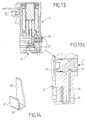
- this return means is produced in the form a small leaf 32 in spring steel.
- This blade has two branches: one embedded, by one of its ends, in the body of the sub-assembly 12 pneumatic switching, and the other housed at its end in a retaining groove 33 provided for this purpose in the manual control 29.
- the end of the leaf spring 32 which is embedded in the body of the pneumatic switching sub-assembly 12 may be fitted with retaining pins 35.
- a cavity 34 is provided, receiving the leaf spring 32, while allowing it a certain deflection in flexion, this provision being adopted for the reasons set out below.
- the leaf spring 32 In the rest position, that is to say when the manual control 29 is not actuated, the leaf spring 32 abuts on the external face of the cavity 34 (position illustrated in Figure 13a). When activating the order manually according to arrow F, the leaf spring 32 deforms by bending and it exerts a movement against displacement along F of the command manual, but this effort is much lower than that required for actuation of this manual control. When the manual control is released, the force generated by the leaf spring brings the manual control back to its rest position, until the blade 32 comes into abutment on the external face from its cavity 34.
Abstract
Description
La présente invention est relative à des perfectionnements apportés aux électrovannes.The present invention relates to improvements made to solenoids.
Elle se réfère plus particulièrement aux électrovannes comportant un sous-ensemble électro-aimant et un sous-ensemble de commutation pneumatique à clapet, qui est associé mécaniquement audit sous-ensemble électro-aimant, le sous-ensemble de commutation pneumatique étant constitué d'un corps enfermant le clapet emprisonné entre deux sièges d'étanchéité en vis-à-vis, le mouvement dudit clapet étant provoqué d'une part par un ressort situé dans le noyau mobile du sous-ensemble électro-aimant, par l'intermédiaire d'un poussoir, et d'autre part par un moyen venant plaquer le clapet sur le siège supérieur du sous-ensemble de commutation pneumatique lorsque l'électro-aimant est alimenté.It refers more particularly to solenoid valves comprising a sub-assembly electromagnet and a pneumatic switching sub-assembly to valve, which is mechanically associated with said electromagnet sub-assembly, the pneumatic switching sub-assembly consisting of a body enclosing the valve trapped between two sealing seats facing each other, the movement of said valve being caused on the one hand by a spring located in the moving core of the electromagnet sub-assembly, via a pusher, and on the other hand by a means coming to press the valve on the seat upper of the pneumatic switching sub-assembly when the electromagnet is powered.
L'un des problèmes techniques qui se pose lors de la conception de telles électrovannes est celui de l'assemblage du sous-ensemble électro-aimant sur le sous-ensemble de commutation pneumatique. En effet, un tel assemblage doit répondre notamment aux exigences ci-après :
- facilité de mise en oeuvre et d'automatisation de l'assemblage ;
- faible coût de revient ;
- indémontabilité ;
- possibilité d'utilisation de l'assemblage sur des pièces usinées.
- ease of implementation and automation of assembly;
- low cost price;
- non-removable;
- possibility of using the assembly on machined parts.
Certaines de ces exigences sont contradictoires notamment la possibilité d'utiliser l'assemblage sur des pièces usinées, qualité qui se traduit généralement par une augmentation des coûts.Some of these requirements are contradictory, in particular the possibility to use the assembly on machined parts, quality which translates usually by increasing costs.
L'invention s'est fixé pour objectif d'apporter une électrovanne qui résout tous ces problèmes techniques en apportant en outre d'autres avantages qui seront spécifiés ci-après.The invention set itself the objective of providing a solenoid valve which solves all these technical problems by bringing other advantages which will be specified below.
L'électrovanne objet de la présente invention est caractérisée en ce que son sous-ensemble électro-aimant comporte au niveau de son plan d'assemblage sur le sous-ensemble de commutation pneumatique, quatre plots cylindriques munis chacun d'une cavité transversale aménagée sur la génératrice et se terminant par un tronc de sphère et en ce que le sous-ensemble de commutation pneumatique comporte, au niveau de son plan d'assemblage avec le sous-ensemble électro-aimant, quatre cavités cylindriques, conçues de façon à recevoir les plots du sous-ensemble électro-aimant, des cavités transversales étant aménagées sur le corps du sous-ensemble de commutation pneumatique, ces cavités venant mourir sur la génératrice respective des cavités recevant les plots et, l'ensemble de chacune desdites cavités se termine par un tronc de sphère, de façon qu'après assemblage des deux sous-ensembles, les cavités transversales des plots du sous-ensemble électro-aimant tombent en regard des cavités transversales dudit sous-ensemble de commutation pneumatique en délimitant des logements, recevant chacun une bille .The solenoid valve object of the present invention is characterized in that its electromagnet sub-assembly has at its assembly plane on the pneumatic switching sub-assembly, four cylindrical studs each provided with a transverse cavity arranged on the generator and is ending with a sphere trunk and in that the subset of pneumatic switching comprises, at its assembly plane with the electromagnet sub-assembly, four cylindrical cavities, designed so to receive the pads of the electromagnet sub-assembly, transverse cavities being arranged on the body of the pneumatic switching sub-assembly, these cavities coming to die on the respective generator of the cavities receiving the studs and, the assembly of each of said cavities ends in a trunk of sphere, so that after assembly of the two sub-assemblies, the cavities transverse of the pads of the electromagnet sub-assembly fall opposite transverse cavities of said pneumatic switching sub-assembly by delimiting housings, each receiving a ball.
Selon la présente invention, chaque cavité transversale du sous-ensemble de commutation pneumatique présente un diamètre inférieur au diamètre des billes.According to the present invention, each transverse cavity of the subset of pneumatic switching has a diameter smaller than the diameter of the balls.
Selon une autre caractéristique de l'électrovanne objet de l'invention, le moyen venant plaquer le clapet sur le siège supérieur du sous-ensemble de commutation pneumatique est réalisé sous la forme d'une fonction « rappel élastique » intégrée dans le poussoir-clapet. According to another characteristic of the solenoid valve object of the invention, the means pressing the valve on the upper seat of the sub-assembly of pneumatic switching is carried out as a "reminder" function elastic ”integrated in the valve plug.
Selon encore une autre caractéristique de cette invention, l'électrovanne comporte une commande manuelle qui est constituée d'une pièce de forme cylindrique assurant, d'une part le déplacement du clapet du siège inférieur vers le siège supérieur et, d'autre part l'étanchéité du sous-ensemble de commutation pneumatique par une fonction d'étanchéité intégrée dans cette commande manuelle.According to yet another characteristic of this invention, the solenoid valve has a manual control which consists of a shaped part cylindrical ensuring, on the one hand the displacement of the valve of the lower seat towards the upper seat and, on the other hand, the sealing of the sub-assembly of pneumatic switching by a sealing function integrated in this manual command.
Selon l'invention, ladite commande manuelle peut être munie d'un moyen de rappel, assurant son retour en position initiale lorsqu'elle n'est plus actionnée, ce moyen de rappel étant réalisé sous la forme d'une lame en acier à ressort qui est encastrée à l'une de ses extrémités dans le corps du sous-ensemble de commutation pneumatique et qui est logée, à son autre extrémité, dans la gorge de retenue de la commande manuelle. L'extrémité de cette lame qui est encastrée dans le corps du sous-ensemble de commutation pneumatique est de préférence munie d'ergots de retenue.According to the invention, said manual control can be provided with a means of recall, ensuring its return to the initial position when it is no longer actuated, this return means being produced in the form of a spring steel blade which is embedded at one of its ends in the body of the subset of pneumatic switching and which is housed at its other end in the groove manual control retainer. The end of this blade which is embedded in the body of the pneumatic switching sub-assembly is preferably fitted with retaining pins.
D'autres caractéristiques et avantages de la présente invention ressortiront de la description faite ci-après, en référence aux dessins annexés qui en illustrent des exemples de réalisation dépourvus de tout caractère limitatif. Sur les dessins :
- les figures 1a et 1b représentent respectivement, en élévation frontale et latérale, le sous-ensemble électro-aimant de l'électrovanne objet de l'invention ;
- les figures 2a et 2b représentent respectivement, en élévation latérale et en plan, le sous-ensemble de commutation pneumatique de l'électrovanne selon l'invention ;
- les figures 3a à 3c sont des vues en élévation frontale représentant les différentes phases de l'assemblage du sous-ensemble électro-aimant sur le sous-ensemble de commutation pneumatique ;
- la figure 4 est une vue en élévation latérale de l'assemblage ainsi réalisé ;
- la figure 4a représente, à échelle agrandie, un détail de la figure 4 ;
- la figure 5 est une vue en coupe axiale verticale de l'électrovanne objet de l'invention, illustrant un exemple de réalisation de la liaison élastique entre le clapet du sous-ensemble de commutation pneumatique et le noyau mobile du sous-ensemble électro-aimant ;
- la figure 6 est une vue en perspective de la liaison élastique mise en oeuvre dans l'électrovanne illustrée par la figure 5 ;
- la figure 7 est une vue en coupe axiale verticale d'une électrovanne comportant un autre exemple de réalisation de cette liaison élastique ;
- la figure 8 est une vue en perspective de la liaison élastique mise en oeuvre dans l'électrovanne illustrée par la figure 7 ;
- la figure 9 est une vue en coupe axiale verticale d'une électrovanne comportant une commande manuelle intégrant une fonction d'étanchéité ;
- la figure 9a représente, à échelle agrandie, le détail de cette commande manuelle selon la figure 9 ;
- la figure 10 représente en perspective cette commande manuelle ;
- la figure 11 est une vue en coupe axiale verticale d'une électrovanne comportant un autre exemple de réalisation d'une commande manuelle intégrant une fonction d'étanchéité ;
- la figure 11 a représente, à échelle agrandie, le détail de cette commande manuelle selon la figure 11 ;
- la figure 12 représente en perspective cette commande manuelle ;
- la figure 13 est une vue, en coupe axiale verticale, d'une électrovanne dans laquelle, selon l'invention, la commande manuelle est munie d'un moyen de rappel réalisé sous la forme d'une lame en acier à ressort ;
- la figure 13a illustre, à plus grande échelle, un détail de la figure 13 et
- la figure 14 est une vue en perspective du moyen de rappel mis en oeuvre dans l'électrovanne représentée sur la figure 13.
- Figures 1a and 1b show respectively, in front and side elevation, the electromagnet sub-assembly of the solenoid valve object of the invention;
- Figures 2a and 2b show respectively, in side elevation and in plan, the pneumatic switching sub-assembly of the solenoid valve according to the invention;
- FIGS. 3a to 3c are front elevation views showing the different phases of the assembly of the electromagnet sub-assembly on the pneumatic switching sub-assembly;
- Figure 4 is a side elevational view of the assembly thus produced;
- Figure 4a shows, on an enlarged scale, a detail of Figure 4;
- Figure 5 is a vertical axial sectional view of the solenoid valve object of the invention, illustrating an embodiment of the elastic connection between the valve of the pneumatic switching sub-assembly and the movable core of the electromagnet sub-assembly ;
- Figure 6 is a perspective view of the elastic connection implemented in the solenoid valve illustrated in Figure 5;
- Figure 7 is a vertical axial sectional view of a solenoid valve comprising another embodiment of this elastic connection;
- Figure 8 is a perspective view of the elastic connection implemented in the solenoid valve illustrated in Figure 7;
- Figure 9 is a vertical axial sectional view of a solenoid valve comprising a manual control incorporating a sealing function;
- FIG. 9a represents, on an enlarged scale, the detail of this manual control according to FIG. 9;
- Figure 10 shows in perspective this manual control;
- Figure 11 is a vertical axial sectional view of a solenoid valve comprising another embodiment of a manual control incorporating a sealing function;
- FIG. 11 a represents, on an enlarged scale, the detail of this manual control according to FIG. 11;
- Figure 12 shows in perspective this manual control;
- FIG. 13 is a view, in vertical axial section, of a solenoid valve in which, according to the invention, the manual control is provided with a return means produced in the form of a spring steel blade;
- FIG. 13a illustrates, on a larger scale, a detail of FIG. 13 and
- FIG. 14 is a perspective view of the return means used in the solenoid valve shown in FIG. 13.
En se référant aux dessins, on voit que la présente invention se réfère à une
électrovanne comportant, d'une part un sous-ensemble électro-aimant désigné
dans son ensemble par la référence 10 et, d'autre part un sous-ensemble de
commutation pneumatique désigné dans son ensemble par la référence 12.
Des moyens assurent l'assemblage des deux sous-ensemble 10 et 12 et, ainsi
qu'on l'a mentionné ci-dessus, la présente invention se réfère notamment à de
tels moyens.Referring to the drawings, it can be seen that the present invention refers to a
solenoid valve comprising, on the one hand a designated electromagnet sub-assembly
as a whole by the
Le sous-ensemble de commutation pneumatique 12 est constitué d'un corps
enfermant un clapet 14, réalisé en élastomère, qui est emprisonné entre deux
sièges d'étanchéité 15, 16, en vis-à-vis. Le mouvement du clapet 14 dans le
corps du sous-ensemble de commutation pneumatique est provoqué, d'une part
par un ressort 17 positionné dans le noyau mobile 18 du sous-ensemble
électro-aimant 10, par l'intermédiaire d'un poussoir et, d'autre part par un
moyen de rappel du clapet.The
En position repos, c'est-à-dire lorsque l'électro-aimant n'est pas alimenté, le
ressort 17 repousse le noyau mobile 18 de manière que celui-ci vienne plaquer
le clapet 14, par l'intermédiaire de son poussoir, sur le siège 16 de la voie
inférieure de l'électrovanne.In the rest position, that is to say when the electromagnet is not supplied, the
spring 17 pushes back the
En position électrovanne ouverte, c'est-à-dire lorsque l'électro-aimant est
alimenté, l'effort magnétique qu'il génère dans le noyau mobile 18 est plus
important que l'effort du ressort 17 et dans ces conditions, le noyau mobile vient
se coller sur le noyau fixe 19 du sous-ensemble 10 et il n'exerce plus d'effort
sur le clapet 14. Le moyen de rappel du clapet 14 plaque alors ce dernier sur le
siège supérieur 15 du sous-ensemble 12.In the open solenoid valve position, i.e. when the electromagnet is
powered, the magnetic force it generates in the
La présente invention vise en premier lieu un moyen d'assemblage mécanique
du sous-ensemble électro-aimant 10 sur le sous-ensemble de commutation
pneumatique 12. Un exemple de réalisation de ce moyen d'assemblage est
illustré par les figures 1a à 4a.The present invention is primarily aimed at a mechanical assembly means
of the
Comme on le voit sur ces figures, le sous-ensemble électro-aimant 10
comporte, au niveau de son plan d'assemblage avec le sous-ensemble de
commutation magnétique 12, quatre plots cylindriques 20 qui sont conçus de
façon à recevoir des billes telles que 21 dans des cavités transversales 22
aménagées sur la génératrice respective des plots et se terminant chacune par
un tronc de sphère.As can be seen in these figures, the
Le sous-ensemble de commutation pneumatique 12 comporte, au niveau de
son plan d'assemblage avec le sous-ensemble électro-aimant 10, quatre
cavités cylindriques 23 qui sont conçues de façon à recevoir les plots 20 du
sous-ensemble électro-aimant 10. Des cavités transversales 24 sont
aménagées sur le corps du sous-ensemble de commutation pneumatique 12 et
ces cavités 24 viennent mourir sur une génératrice respective des cavités
cylindriques 23 destinées à recevoir les plots 20. Chaque extrémité de cavités
telles que 24 se termine par un tronc de sphère, la disposition étant telle,
qu'après pré-montage l'un sur l'autre des deux sous-ensembles 10 et 12, les
cavités transversales 22 des plots 20 tombent en regard des cavités
transversales 24 du sous-ensemble de commutation pneumatique 12 formant
ainsi respectivement un logement pour une bille 21.The
Afin de générer un effort de maintien entre les deux sous-ensembles 10 et 12,
comme le ferait par exemple un assemblage par vis selon la technique
antérieure, les cavités transversales 22 et 24 sont excentrées respectivement
les unes par rapport aux autres afin que chaque bille telle que 21, en place
dans son logement, génère une légère déformation des plots 20, jusqu'à ce que
les cavités transversales soient en regard les unes des autres.In order to generate a holding force between the two
Les figures 3a à 3c illustrent les différentes étapes de l'assemblage de
l'ensemble 10 sur l'ensemble 12. La figure 4 représente l'assemblage après
réalisation et le détail de la figure 4 montre une bille 21 en place dans son
logement délimité par les cavités transversales 22 des plots tels que 20 et les
cavités transversales 24 du sous-ensemble de commutation pneumatique 12.Figures 3a to 3c illustrate the different stages of the assembly of
Le système d'assemblage ainsi décrit est très simple à réaliser et à mettre en
oeuvre étant donné que les billes 21, qui en assurent le verrouillage et qui
peuvent être réalisées en acier ou en tout autre matériau, n'exigent aucune
orientation pour leur assemblage, ce qui permet d'éviter des investissements
très importants, une simple presse manuelle permettant de mettre en oeuvre
cette technique originale d'assemblage. Par ailleurs, l'automatisation de
l'assemblage est très facile à réaliser compte tenu du fait qu' il est possible
d'effectuer facilement, pour un coût modique, une alimentation automatique des
billes telles que 21.The assembly system thus described is very simple to produce and to set up.
work since the
L'indémontabilité de l'assemblage, c'est-à-dire des billes 21, est obtenue, selon
l'invention, par le fait que chaque cavité transversale 24 du sous-ensemble de
commutation pneumatique 12 présente un diamètre inférieur au diamètre des
billes telles que 21, ce qui rend impossible le démontage de ces dernières par
n'importe quel type d'outil, sans détruire l'électrovanne.The non-demountability of the assembly, that is to say of the
Du fait de la forme des plots 20 ainsi que des cavités 23, il est très facile de
mettre en oeuvre ce mode d'assemblage avec des pièces usinées, par exemple
dans le cas où l'on souhaiterait utiliser le sous-ensemble électro-aimant 10 sur
un sous-ensemble de commutation 12 métallique.Due to the shape of the
Ainsi qu'on l'a mentionné ci-dessus, les électrovannes de ce type comportent
un moyen de rappel du clapet qui permet de plaquer ce dernier sur le siège
supérieur 15 du sous-ensemble de commutation pneumatique 12 lorsque
l'électrovanne est en position ouverte, c'est-à-dire lorsque l'électro-aimant est
alimenté. Dans l'état actuel de la technique, ce moyen de rappel est réalisé
sous la forme d'un ressort qui est situé sous le clapet et qui est en appui autour
du siège inférieur du sous-ensemble de commutation pneumatique.As mentioned above, solenoid valves of this type have
a means of returning the valve which allows it to be pressed onto the seat
upper 15 of the
La présente invention se propose de supprimer ce ressort et de remplacer son effet par une fonction « rappel élastique » qui est intégrée dans le porte-clapet de l'électrovanne. Cette solution permet de réduire les coûts du fait de la suppression du ressort et de la main-d'oeuvre nécessaire à sa mise en place.The present invention proposes to remove this spring and replace its effect by an "elastic return" function which is integrated in the valve holder of the solenoid valve. This solution reduces costs due to the removal of the spring and the labor necessary for its installation.
Les figures 5 à 8 illustrent des exemples de réalisation non limitatifs de cette fonction ressort élastique.Figures 5 to 8 illustrate non-limiting exemplary embodiments of this elastic spring function.
Dans le mode de réalisation illustré par les figures 5 et 6, le clapet 14 du sous-ensemble
de commutation pneumatique 12 est attelé au noyau mobile 18 du
sous-ensemble électro-aimant 12 par un accouplement élastique afin de
garantir, lors de l'ouverture de l'électrovanne par mise sous tension du sous-ensemble
électro-aimant 10, que le clapet 14 viendra bien se plaquer sur le
siège supérieur 15 et donc que le siège 16 de la voie inférieure de
l'électrovanne soit ouvert, ceci même sans pression. La fonction rappel
élastique ainsi réalisée entre le noyau mobile 18 et le clapet 14 permet de
garantir à la fois le contact du clapet 14 sur son siège supérieur 15 et le contact
du noyau mobile 18 sur le noyau fixe 19 du sous-ensemble électro-aimant 10.In the embodiment illustrated by FIGS. 5 and 6, the
La raison pour laquelle il est nécessaire de garantir un contact des deux noyaux
18 et 19 du sous-ensemble électro-aimant 10 est la limitation de la montée en
température de ce sous-ensemble lors de l'alimentation de ce dernier. La raison
pour laquelle il convient de garantir un contact du clapet 14 sur son siège
supérieur 15 lors de l'alimentation du sous-ensemble électro-aimant 10 est la
garantie d'assurer l'étanchéité de cette voie supérieure.The reason why it is necessary to guarantee contact of the two
Ainsi qu'on le voit sur les figures 5 et 6, cette liaison élastique est obtenue selon
cet exemple de réalisation de l'invention, à l'aide d'une pièce d'attelage,
désignée dans son ensemble par la référence 25, qui forme porte-clapet et qui
est munie de pattes telles que 26 (figure 6) venant s'accrocher sur une saillie de
forme conique 27 qui est prévue à l'extrémité du noyau mobile 18 du sous-ensemble
électro-aimant 10. La déformation de cet attelage porte-clapet 25 /
noyau 18 permet également, lors de l'ouverture de l'électrovanne, de garantir la
fermeture du siège supérieur 15.As seen in Figures 5 and 6, this elastic connection is obtained according to
this exemplary embodiment of the invention, using a coupling piece,
designated as a whole by the
On notera que la solution décrite ci-dessus qui permet effectivement de supprimer le ressort sous clapet des électrovannes selon l'état antérieur de la technique, d'une part réduit le nombre de composants de cette électrovanne, et d'autre part permet de s'affranchir de la tolérance de fabrication sur les efforts du ressort qui génèrent des contraintes supplémentaires entraínant une pénalisation des performances pneumatiques de l'électrovanne.Note that the solution described above which effectively allows remove the valve spring from the solenoid valves according to the previous state of the technical, on the one hand reduces the number of components of this solenoid valve, and on the other hand allows to overcome the manufacturing tolerance on the efforts of the spring which generate additional stresses resulting in penalization of the pneumatic performance of the solenoid valve.
Cette solution présente donc un intérêt économique indéniable.This solution therefore presents an undeniable economic interest.
Dans le second exemple de réalisation, illustré par les figures 7 et 8, la fonction
rappel élastique du clapet 24 est intégrée dans le porte-clapet 25'. Celui-ci est
réalisé de préférence en matière plastique et il est muni à sa partie inférieure de
lames de ressort de forme hélicoïdale telles que 28 venant au contact de part et
d'autre du siège inférieur du sous-ensemble de commutation pneumatique 12.
L'élasticité de ces lames de ressort permet de garantir la fonction rappel
élastique du clapet.In the second embodiment, illustrated by FIGS. 7 and 8, the function
elastic return of the
Ainsi qu'on l'a décrit ci-dessus, l'électrovanne est actionnée par l'alimentation du sous-ensemble électro-aimant 10. Il est cependant prévu, comme dans la technique antérieure, une commande manuelle permettant d'actionner l'électrovanne sans avoir recours à une alimentation de ce sous-ensemble 10. Selon l'état antérieur de la technique, cette commande manuelle est obtenue à l'aide d'une pièce présentant une forme cylindrique et devant assurer deux fonctions :
- le déplacement du clapet du siège inférieur vers le siège supérieur, ceci grâce à une pente ménagée en bout de la commande manuelle qui, lors de l'actionnement de cette dernière par un mouvement de translation, transmet un mouvement linéaire perpendiculaire à son mouvement de translation, ce mouvement linéaire perpendiculaire étant transmis au clapet par l'intermédiaire du porte-clapet et du noyau mobile ;
- une fonction d'étanchéité de l'ensemble de
commutation pneumatique 12, ceci même lors de son actionnement.
- the movement of the valve from the lower seat to the upper seat, this thanks to a slope formed at the end of the manual control which, when actuated by a translational movement, transmits a linear movement perpendicular to its translational movement , this perpendicular linear movement being transmitted to the valve via the valve holder and the movable core;
- a sealing function of the
pneumatic switching assembly 12, even when it is actuated.
Dans les solutions actuellement utilisées, la fonction étanchéité est assurée à l'aide d'un joint torique qui est monté dans une gorge prévue sur la commande manuelle. La présente invention se propose d'apporter une solution permettant une suppression de ce joint torique, ce qui se traduit par une réduction des coûts de revient résultant de cette suppression et de celle de la main-d'oeuvre nécessaire à la mise en place d'un tel joint. La solution apportée par la présente invention consiste à intégrer la fonction d'étanchéité dans la commande manuelle.In the solutions currently used, the sealing function is ensured at using an O-ring which is mounted in a groove provided on the order manual. The present invention proposes to provide a solution allowing a removal of this O-ring, which results in a reduction of production costs resulting from this abolition and from that of labor necessary for the installation of such a seal. The solution provided by this invention consists in integrating the sealing function in the control manual.
Dans l'exemple de réalisation illustré par les figures 9 à 10, cette fonction
d'étanchéité est obtenue à l'aide d'une lèvre 30 qui est intégrée sur la pièce
cylindrique 29 constituant la commande manuelle. Afin de garantir une bonne
étanchéité, la lèvre 30 doit être suffisamment souple pour épouser les parois du
logement de la commande manuelle (voir la figure 9a) tout en étant
suffisamment dure pour ne pas s'affaisser lors de l'actionnement de la
commande manuelle. De préférence, cette commande manuelle 29 intégrant la
lèvre 30 sera réalisée en une matière thermoplastique élastomère.In the embodiment illustrated in FIGS. 9 to 10, this function
sealing is obtained using a
Un autre exemple de réalisation de cette commande manuelle intégrant la
fonction d'étanchéité est illustré par les figures 11 à 12. Dans cet exemple de
réalisation, la fonction d'étanchéité intégrée est obtenue à l'aide d'une forme en
tronc de tore 31, équivalente à une forme de joint torique, qui est réalisée sur la
périphérie de la commande manuelle 29'. Le matériau constituant la commande
manuelle 29' doit répondre aux mêmes exigences que celles mentionnées ci-dessus
à propos de la commande manuelle 29 et dans ces conditions, il est
préférable de réaliser cette commande manuelle 29' en thermoplastique
élastomère.Another example of embodiment of this manual control integrating the
sealing function is illustrated in FIGS. 11 to 12. In this example of
embodiment, the integrated sealing function is obtained using a
Dans les électrovannes auxquelles s'applique la présente invention, on prévoit des moyens permettant un retour en position initiale de la commande manuelle lorsque celle-ci n'est plus actionnée. Dans l'état antérieur de la technique, ces moyens sont réalisés sous la forme d'un ressort qui est situé à l'une des extrémités de la commande manuelle de façon à repousser cette dernière dans sa position initiale, permettant ainsi au clapet du sous-ensemble de commutation pneumatique d'être libéré de cette commande manuelle. La position initiale de la commande manuelle est généralement obtenue à l'aide d'une pièce supplémentaire formant butée, par exemple une goupille, car il n'est possible de monter la commande manuelle dans son logement que de l'extérieur du corps du sous-ensemble de commutation pneumatique. Il est donc nécessaire d'ajouter la butée après montage de la commande manuelle.In the solenoid valves to which the present invention applies, provision is made means allowing the manual control to return to the initial position when it is no longer actuated. In the prior art, these means are made in the form of a spring which is located at one of the ends of the manual control so as to push it back into its initial position, thus allowing the sub-assembly valve to pneumatic switching to be released from this manual control. The initial position of the manual control is generally obtained using an additional piece forming a stop, for example a pin, because it the manual control can only be mounted in its housing outside the body of the pneumatic switching sub-assembly. It is therefore necessary to add the stop after mounting the manual control.
La présente invention se propose de supprimer le ressort de retour en position initiale de la commande manuelle ainsi que la butée de cette dernière, ces deux fonctions étant obtenues à l'aide d'un élément unique. Par ailleurs, la solution apportée par l'invention et qui est décrite ci-après, permet d'obtenir une fonction ressort plus facile à manipuler ou à distribuer de façon automatique, ce qui permet de réduire les coûts.The present invention proposes to eliminate the return spring in position initial of the manual control as well as the stop of the latter, these two functions being obtained using a single element. Besides, the solution provided by the invention and which is described below, makes it possible to obtain a function spring easier to handle or distribute automatically, which helps reduce costs.
Un exemple de réalisation de ce moyen de rappel de la commande manuelle est illustré par les figures 13 à 14.An exemplary embodiment of this means of recalling the manual control is illustrated in Figures 13 to 14.
Comme on le voit sur ces figures, ce moyen de rappel est réalisé sous la forme
d'une petite lame 32 en acier à ressort. Cette lame comporte deux branches :
l'une encastrée, par l'une de ses extrémités, dans le corps du sous-ensemble
12 de commutation pneumatique, et l'autre logée, à son extrémité, dans une
gorge de retenue 33 prévue à cet effet dans la commande manuelle 29. As can be seen in these figures, this return means is produced in the form
a
Ainsi qu'on le voit sur la figure 4, l'extrémité de lame ressort 32 qui est
encastrée dans le corps du sous-ensemble de commutation pneumatique 12
peut être munie d'ergots de retenue 35.As can be seen in FIG. 4, the end of the
Par ailleurs, dans le corps du sous-ensemble 12, sous le logement de la
commande manuelle 29, est prévue une cavité 34, recevant la lame ressort 32,
tout en lui permettant un certain débattement en flexion, cette disposition étant
adoptée pour les motifs exposés ci-après.Furthermore, in the body of the
En position repos, c'est-à-dire lorsque la commande manuelle 29 n'est pas
actionnée, la lame ressort 32 vient en butée sur la face externe de la cavité 34
(position illustrée par la figure 13a). Lors de l'actionnement de la commande
manuelle selon la flèche F, la lame ressort 32 se déforme par flexion et elle
exerce un mouvement à l'encontre du déplacement selon F de la commande
manuelle, mais cet effort est bien inférieur à celui nécessaire à l'actionnement
de cette commande manuelle. Lors du relâchement de la commande manuelle,
l'effort généré par la lame ressort ramène la commande manuelle dans sa
position repos, jusqu'à ce que la lame 32 revienne en butée sur la face externe
de sa cavité 34.In the rest position, that is to say when the
Il demeure bien entendu que la présente invention n'est pas limitée aux exemples de réalisation décrits et représentés ci-dessus, mais qu'elle en englobe toutes les variantes.It remains to be understood that the present invention is not limited to examples of embodiments described and represented above, but that it includes all variants.
Claims (13)
Applications Claiming Priority (2)
| Application Number | Priority Date | Filing Date | Title |
|---|---|---|---|
| FR0200437 | 2002-01-15 | ||
| FR0200437A FR2834767B1 (en) | 2002-01-15 | 2002-01-15 | IMPROVEMENTS ON ELECTROVALVES |
Publications (2)
| Publication Number | Publication Date |
|---|---|
| EP1327808A1 true EP1327808A1 (en) | 2003-07-16 |
| EP1327808B1 EP1327808B1 (en) | 2007-02-21 |
Family
ID=8871294
Family Applications (1)
| Application Number | Title | Priority Date | Filing Date |
|---|---|---|---|
| EP02293127A Expired - Lifetime EP1327808B1 (en) | 2002-01-15 | 2002-12-17 | Improvements in electrovalves |
Country Status (5)
| Country | Link |
|---|---|
| US (1) | US6820650B2 (en) |
| EP (1) | EP1327808B1 (en) |
| AT (1) | ATE354756T1 (en) |
| DE (1) | DE60218277T2 (en) |
| FR (1) | FR2834767B1 (en) |
Cited By (10)
| Publication number | Priority date | Publication date | Assignee | Title |
|---|---|---|---|---|
| WO2005040654A3 (en) * | 2003-10-21 | 2005-06-16 | Klaus Perthel | Electromagnetic valve |
| US9645584B2 (en) | 2014-09-17 | 2017-05-09 | Honeywell International Inc. | Gas valve with electronic health monitoring |
| US9657946B2 (en) | 2012-09-15 | 2017-05-23 | Honeywell International Inc. | Burner control system |
| US9683674B2 (en) | 2013-10-29 | 2017-06-20 | Honeywell Technologies Sarl | Regulating device |
| US9835265B2 (en) | 2011-12-15 | 2017-12-05 | Honeywell International Inc. | Valve with actuator diagnostics |
| US9841122B2 (en) | 2014-09-09 | 2017-12-12 | Honeywell International Inc. | Gas valve with electronic valve proving system |
| US9846440B2 (en) | 2011-12-15 | 2017-12-19 | Honeywell International Inc. | Valve controller configured to estimate fuel comsumption |
| US9851103B2 (en) | 2011-12-15 | 2017-12-26 | Honeywell International Inc. | Gas valve with overpressure diagnostics |
| US10422531B2 (en) | 2012-09-15 | 2019-09-24 | Honeywell International Inc. | System and approach for controlling a combustion chamber |
| US10503181B2 (en) | 2016-01-13 | 2019-12-10 | Honeywell International Inc. | Pressure regulator |
Families Citing this family (15)
| Publication number | Priority date | Publication date | Assignee | Title |
|---|---|---|---|---|
| US20060037810A1 (en) * | 2004-08-19 | 2006-02-23 | Prince David B | Muffler for pneumatic tools |
| FR2885397B1 (en) * | 2005-05-09 | 2007-06-22 | Asco Joucomatic | IMPROVEMENTS TO SOLENOID VALVES. |
| US9995486B2 (en) | 2011-12-15 | 2018-06-12 | Honeywell International Inc. | Gas valve with high/low gas pressure detection |
| US8899264B2 (en) | 2011-12-15 | 2014-12-02 | Honeywell International Inc. | Gas valve with electronic proof of closure system |
| US8839815B2 (en) | 2011-12-15 | 2014-09-23 | Honeywell International Inc. | Gas valve with electronic cycle counter |
| US8905063B2 (en) | 2011-12-15 | 2014-12-09 | Honeywell International Inc. | Gas valve with fuel rate monitor |
| US9074770B2 (en) | 2011-12-15 | 2015-07-07 | Honeywell International Inc. | Gas valve with electronic valve proving system |
| US9557059B2 (en) | 2011-12-15 | 2017-01-31 | Honeywell International Inc | Gas valve with communication link |
| US8947242B2 (en) | 2011-12-15 | 2015-02-03 | Honeywell International Inc. | Gas valve with valve leakage test |
| US10024439B2 (en) | 2013-12-16 | 2018-07-17 | Honeywell International Inc. | Valve over-travel mechanism |
| US9851003B2 (en) * | 2014-10-06 | 2017-12-26 | Sonnax Industries, Inc. | Remanufactured solenoid valves and devices for remanufacturing solenoid valves |
| US10564062B2 (en) | 2016-10-19 | 2020-02-18 | Honeywell International Inc. | Human-machine interface for gas valve |
| US11073281B2 (en) | 2017-12-29 | 2021-07-27 | Honeywell International Inc. | Closed-loop programming and control of a combustion appliance |
| US10697815B2 (en) | 2018-06-09 | 2020-06-30 | Honeywell International Inc. | System and methods for mitigating condensation in a sensor module |
| US11428340B2 (en) * | 2019-05-29 | 2022-08-30 | Dana Canada Corporation | Electrically actuated flow control valve and method for operation of the flow control valve |
Citations (3)
| Publication number | Priority date | Publication date | Assignee | Title |
|---|---|---|---|---|
| FR2267009A7 (en) * | 1974-04-02 | 1975-10-31 | Interapp Gmbh | Valve block assembly system - has valve bodies with union surfaces and recesses on each side |
| US4552179A (en) * | 1983-08-25 | 1985-11-12 | Ckd Corporation | Miniature solenoid valve |
| FR2795494A1 (en) * | 1999-06-25 | 2000-12-29 | York Neige | Supply device for snow gun comprises valve with through intake channel and communication between intake and outlet via bore containing slide valve |
Family Cites Families (2)
| Publication number | Priority date | Publication date | Assignee | Title |
|---|---|---|---|---|
| FR2603970B1 (en) * | 1986-09-15 | 1988-12-02 | Telemecanique Electrique | SMALL TAMPER SOLENOID VALVE |
| IT1258956B (en) * | 1992-06-08 | 1996-03-11 | MINIATURIZED SOLENOID VALVE DEVICE AND PROCEDURE FOR ITS PREPARATION |
-
2002
- 2002-01-15 FR FR0200437A patent/FR2834767B1/en not_active Expired - Fee Related
- 2002-12-17 EP EP02293127A patent/EP1327808B1/en not_active Expired - Lifetime
- 2002-12-17 DE DE60218277T patent/DE60218277T2/en not_active Expired - Lifetime
- 2002-12-17 AT AT02293127T patent/ATE354756T1/en not_active IP Right Cessation
-
2003
- 2003-01-09 US US10/338,488 patent/US6820650B2/en not_active Expired - Fee Related
Patent Citations (3)
| Publication number | Priority date | Publication date | Assignee | Title |
|---|---|---|---|---|
| FR2267009A7 (en) * | 1974-04-02 | 1975-10-31 | Interapp Gmbh | Valve block assembly system - has valve bodies with union surfaces and recesses on each side |
| US4552179A (en) * | 1983-08-25 | 1985-11-12 | Ckd Corporation | Miniature solenoid valve |
| FR2795494A1 (en) * | 1999-06-25 | 2000-12-29 | York Neige | Supply device for snow gun comprises valve with through intake channel and communication between intake and outlet via bore containing slide valve |
Cited By (14)
| Publication number | Priority date | Publication date | Assignee | Title |
|---|---|---|---|---|
| WO2005040654A3 (en) * | 2003-10-21 | 2005-06-16 | Klaus Perthel | Electromagnetic valve |
| EP1962004A2 (en) | 2003-10-21 | 2008-08-27 | Adam Opel GmbH | Electromagnetic valve |
| US7722009B2 (en) | 2003-10-21 | 2010-05-25 | Gm Global Technology Operations Inc. | Electromagnetic valve |
| EP1962004A3 (en) * | 2003-10-21 | 2010-11-03 | GM Global Technology Operations, Inc. | Electromagnetic valve |
| US9846440B2 (en) | 2011-12-15 | 2017-12-19 | Honeywell International Inc. | Valve controller configured to estimate fuel comsumption |
| US9835265B2 (en) | 2011-12-15 | 2017-12-05 | Honeywell International Inc. | Valve with actuator diagnostics |
| US9851103B2 (en) | 2011-12-15 | 2017-12-26 | Honeywell International Inc. | Gas valve with overpressure diagnostics |
| US9657946B2 (en) | 2012-09-15 | 2017-05-23 | Honeywell International Inc. | Burner control system |
| US10422531B2 (en) | 2012-09-15 | 2019-09-24 | Honeywell International Inc. | System and approach for controlling a combustion chamber |
| US11421875B2 (en) | 2012-09-15 | 2022-08-23 | Honeywell International Inc. | Burner control system |
| US9683674B2 (en) | 2013-10-29 | 2017-06-20 | Honeywell Technologies Sarl | Regulating device |
| US9841122B2 (en) | 2014-09-09 | 2017-12-12 | Honeywell International Inc. | Gas valve with electronic valve proving system |
| US9645584B2 (en) | 2014-09-17 | 2017-05-09 | Honeywell International Inc. | Gas valve with electronic health monitoring |
| US10503181B2 (en) | 2016-01-13 | 2019-12-10 | Honeywell International Inc. | Pressure regulator |
Also Published As
| Publication number | Publication date |
|---|---|
| FR2834767B1 (en) | 2004-04-16 |
| DE60218277T2 (en) | 2007-11-15 |
| EP1327808B1 (en) | 2007-02-21 |
| ATE354756T1 (en) | 2007-03-15 |
| US6820650B2 (en) | 2004-11-23 |
| DE60218277D1 (en) | 2007-04-05 |
| FR2834767A1 (en) | 2003-07-18 |
| US20030150499A1 (en) | 2003-08-14 |
Similar Documents
| Publication | Publication Date | Title |
|---|---|---|
| EP1327808B1 (en) | Improvements in electrovalves | |
| EP1281878B1 (en) | Pivot pin between two elements | |
| EP0654852A1 (en) | Mixed electrofluidic connector | |
| EP0340161A1 (en) | Elastic hinge for spectacle frame | |
| EP0392307B1 (en) | Push-button, in particular for watch-case | |
| FR2998025A1 (en) | VALVE | |
| FR2512889A1 (en) | HYDRAULIC FORCE AMPLIFIER, IN PARTICULAR FOR BRAKING SYSTEMS OF MOTOR VEHICLES | |
| FR2965683A1 (en) | ELECTROMAGNETIC INSTALLATION AND DRIVING ASSISTANCE INSTALLATION EQUIPPED WITH SUCH A INSTALLATION | |
| CH694279A5 (en) | Electromagnetic fluid control valve has valve plate connected to solenoid shaft by ball joint for aligning action | |
| EP1103991B1 (en) | Solenoid valve with manually operated pushrod | |
| FR2643970A1 (en) | SOLENOID VALVE AND METHOD FOR MOUNTING | |
| FR2808618A1 (en) | CIRCUIT BREAKER COMPRISING, IN AN ENCLOSURE FILLED WITH A DIELECTRIC GAS UNDER PRESSURE, A MOBILE ASSEMBLY | |
| CH635911A5 (en) | MANUALLY CONTROLLED FLUID VALVE. | |
| EP1154104B1 (en) | Key with metal shank and plastic head comprising a blocking case | |
| EP1103992A1 (en) | Miniature electromagnetic valve and assembling procedure | |
| EP0006770B1 (en) | Electromagnetic valve, especially for a carburetor | |
| WO2001073498A1 (en) | Sprung joint with reduced friction | |
| FR2638210A1 (en) | BINDING PART FOR ASSEMBLING PROFILES | |
| EP0549490B1 (en) | Solenoid valve with a flat movable plunger | |
| EP4160026B1 (en) | Actuator with dual electric and pneumatic control | |
| CH714646B1 (en) | Device for attaching a bracelet. | |
| WO2017216504A1 (en) | Quick-release setting tool for an element to be crimped | |
| FR2892849A1 (en) | Fixed and movable contacts locking mechanism for e.g. circuit breaker, has movable contact rigidly fixed to contact holder, and compression spring placed between flange and fixed contact | |
| FR2899721A1 (en) | Bistable operating device for vehicle`s battery circuit breaker case, has movable shaft including free end that is provided in axial support against core that has plane end surface forming support surface, and stop arranged on movable shaft | |
| EP0719969B1 (en) | Safety valve |
Legal Events
| Date | Code | Title | Description |
|---|---|---|---|
| PUAI | Public reference made under article 153(3) epc to a published international application that has entered the european phase |
Free format text: ORIGINAL CODE: 0009012 |
|
| AK | Designated contracting states |
Designated state(s): AT BE BG CH CY CZ DE DK EE ES FI FR GB GR IE IT LI LU MC NL PT SE SI SK TR |
|
| AX | Request for extension of the european patent |
Extension state: AL LT LV MK RO |
|
| 17P | Request for examination filed |
Effective date: 20040102 |
|
| AKX | Designation fees paid |
Designated state(s): AT BE BG CH CY CZ DE DK EE ES FI FR GB GR IE IT LI LU MC NL PT SE SI SK TR |
|
| GRAP | Despatch of communication of intention to grant a patent |
Free format text: ORIGINAL CODE: EPIDOSNIGR1 |
|
| GRAS | Grant fee paid |
Free format text: ORIGINAL CODE: EPIDOSNIGR3 |
|
| GRAA | (expected) grant |
Free format text: ORIGINAL CODE: 0009210 |
|
| AK | Designated contracting states |
Kind code of ref document: B1 Designated state(s): AT BE BG CH CY CZ DE DK EE ES FI FR GB GR IE IT LI LU MC NL PT SE SI SK TR |
|
| PG25 | Lapsed in a contracting state [announced via postgrant information from national office to epo] |
Ref country code: FI Free format text: LAPSE BECAUSE OF FAILURE TO SUBMIT A TRANSLATION OF THE DESCRIPTION OR TO PAY THE FEE WITHIN THE PRESCRIBED TIME-LIMIT Effective date: 20070221 Ref country code: NL Free format text: LAPSE BECAUSE OF FAILURE TO SUBMIT A TRANSLATION OF THE DESCRIPTION OR TO PAY THE FEE WITHIN THE PRESCRIBED TIME-LIMIT Effective date: 20070221 Ref country code: IE Free format text: LAPSE BECAUSE OF FAILURE TO SUBMIT A TRANSLATION OF THE DESCRIPTION OR TO PAY THE FEE WITHIN THE PRESCRIBED TIME-LIMIT Effective date: 20070221 Ref country code: SI Free format text: LAPSE BECAUSE OF FAILURE TO SUBMIT A TRANSLATION OF THE DESCRIPTION OR TO PAY THE FEE WITHIN THE PRESCRIBED TIME-LIMIT Effective date: 20070221 Ref country code: AT Free format text: LAPSE BECAUSE OF FAILURE TO SUBMIT A TRANSLATION OF THE DESCRIPTION OR TO PAY THE FEE WITHIN THE PRESCRIBED TIME-LIMIT Effective date: 20070221 Ref country code: DK Free format text: LAPSE BECAUSE OF FAILURE TO SUBMIT A TRANSLATION OF THE DESCRIPTION OR TO PAY THE FEE WITHIN THE PRESCRIBED TIME-LIMIT Effective date: 20070221 |
|
| REG | Reference to a national code |
Ref country code: GB Ref legal event code: FG4D Free format text: NOT ENGLISH |
|
| RIN1 | Information on inventor provided before grant (corrected) |
Inventor name: SOLET, DANIEL Inventor name: COURPRON, BERNARD Inventor name: VANDAMME, RICHARD |
|
| GBT | Gb: translation of ep patent filed (gb section 77(6)(a)/1977) |
Effective date: 20070221 |
|
| REG | Reference to a national code |
Ref country code: CH Ref legal event code: EP |
|
| REF | Corresponds to: |
Ref document number: 60218277 Country of ref document: DE Date of ref document: 20070405 Kind code of ref document: P |
|
| REG | Reference to a national code |
Ref country code: IE Ref legal event code: FG4D Free format text: LANGUAGE OF EP DOCUMENT: FRENCH |
|
| PG25 | Lapsed in a contracting state [announced via postgrant information from national office to epo] |
Ref country code: SE Free format text: LAPSE BECAUSE OF FAILURE TO SUBMIT A TRANSLATION OF THE DESCRIPTION OR TO PAY THE FEE WITHIN THE PRESCRIBED TIME-LIMIT Effective date: 20070521 Ref country code: BG Free format text: LAPSE BECAUSE OF FAILURE TO SUBMIT A TRANSLATION OF THE DESCRIPTION OR TO PAY THE FEE WITHIN THE PRESCRIBED TIME-LIMIT Effective date: 20070521 |
|
| PG25 | Lapsed in a contracting state [announced via postgrant information from national office to epo] |
Ref country code: ES Free format text: LAPSE BECAUSE OF FAILURE TO SUBMIT A TRANSLATION OF THE DESCRIPTION OR TO PAY THE FEE WITHIN THE PRESCRIBED TIME-LIMIT Effective date: 20070601 |
|
| PG25 | Lapsed in a contracting state [announced via postgrant information from national office to epo] |
Ref country code: PT Free format text: LAPSE BECAUSE OF FAILURE TO SUBMIT A TRANSLATION OF THE DESCRIPTION OR TO PAY THE FEE WITHIN THE PRESCRIBED TIME-LIMIT Effective date: 20070723 |
|
| NLV1 | Nl: lapsed or annulled due to failure to fulfill the requirements of art. 29p and 29m of the patents act | ||
| REG | Reference to a national code |
Ref country code: IE Ref legal event code: FD4D |
|
| PG25 | Lapsed in a contracting state [announced via postgrant information from national office to epo] |
Ref country code: SK Free format text: LAPSE BECAUSE OF FAILURE TO SUBMIT A TRANSLATION OF THE DESCRIPTION OR TO PAY THE FEE WITHIN THE PRESCRIBED TIME-LIMIT Effective date: 20070221 |
|
| PLBE | No opposition filed within time limit |
Free format text: ORIGINAL CODE: 0009261 |
|
| STAA | Information on the status of an ep patent application or granted ep patent |
Free format text: STATUS: NO OPPOSITION FILED WITHIN TIME LIMIT |
|
| PG25 | Lapsed in a contracting state [announced via postgrant information from national office to epo] |
Ref country code: CZ Free format text: LAPSE BECAUSE OF FAILURE TO SUBMIT A TRANSLATION OF THE DESCRIPTION OR TO PAY THE FEE WITHIN THE PRESCRIBED TIME-LIMIT Effective date: 20070221 |
|
| 26N | No opposition filed |
Effective date: 20071122 |
|
| PG25 | Lapsed in a contracting state [announced via postgrant information from national office to epo] |
Ref country code: GR Free format text: LAPSE BECAUSE OF FAILURE TO SUBMIT A TRANSLATION OF THE DESCRIPTION OR TO PAY THE FEE WITHIN THE PRESCRIBED TIME-LIMIT Effective date: 20070522 |
|
| BERE | Be: lapsed |
Owner name: ASCO JOUCOMATIC Effective date: 20071231 |
|
| PG25 | Lapsed in a contracting state [announced via postgrant information from national office to epo] |
Ref country code: MC Free format text: LAPSE BECAUSE OF NON-PAYMENT OF DUE FEES Effective date: 20071231 |
|
| REG | Reference to a national code |
Ref country code: CH Ref legal event code: PL |
|
| GBPC | Gb: european patent ceased through non-payment of renewal fee |
Effective date: 20071217 |
|
| PG25 | Lapsed in a contracting state [announced via postgrant information from national office to epo] |
Ref country code: BE Free format text: LAPSE BECAUSE OF NON-PAYMENT OF DUE FEES Effective date: 20071231 |
|
| PG25 | Lapsed in a contracting state [announced via postgrant information from national office to epo] |
Ref country code: LI Free format text: LAPSE BECAUSE OF NON-PAYMENT OF DUE FEES Effective date: 20071231 Ref country code: CH Free format text: LAPSE BECAUSE OF NON-PAYMENT OF DUE FEES Effective date: 20071231 |
|
| PG25 | Lapsed in a contracting state [announced via postgrant information from national office to epo] |
Ref country code: GB Free format text: LAPSE BECAUSE OF NON-PAYMENT OF DUE FEES Effective date: 20071217 |
|
| PG25 | Lapsed in a contracting state [announced via postgrant information from national office to epo] |
Ref country code: EE Free format text: LAPSE BECAUSE OF FAILURE TO SUBMIT A TRANSLATION OF THE DESCRIPTION OR TO PAY THE FEE WITHIN THE PRESCRIBED TIME-LIMIT Effective date: 20070221 |
|
| PG25 | Lapsed in a contracting state [announced via postgrant information from national office to epo] |
Ref country code: CY Free format text: LAPSE BECAUSE OF FAILURE TO SUBMIT A TRANSLATION OF THE DESCRIPTION OR TO PAY THE FEE WITHIN THE PRESCRIBED TIME-LIMIT Effective date: 20070221 |
|
| PG25 | Lapsed in a contracting state [announced via postgrant information from national office to epo] |
Ref country code: LU Free format text: LAPSE BECAUSE OF NON-PAYMENT OF DUE FEES Effective date: 20071217 |
|
| PG25 | Lapsed in a contracting state [announced via postgrant information from national office to epo] |
Ref country code: TR Free format text: LAPSE BECAUSE OF FAILURE TO SUBMIT A TRANSLATION OF THE DESCRIPTION OR TO PAY THE FEE WITHIN THE PRESCRIBED TIME-LIMIT Effective date: 20070221 |
|
| PGFP | Annual fee paid to national office [announced via postgrant information from national office to epo] |
Ref country code: FR Payment date: 20121130 Year of fee payment: 11 |
|
| PGFP | Annual fee paid to national office [announced via postgrant information from national office to epo] |
Ref country code: IT Payment date: 20121219 Year of fee payment: 11 |
|
| PGFP | Annual fee paid to national office [announced via postgrant information from national office to epo] |
Ref country code: DE Payment date: 20121220 Year of fee payment: 11 |
|
| REG | Reference to a national code |
Ref country code: DE Ref legal event code: R119 Ref document number: 60218277 Country of ref document: DE |
|
| REG | Reference to a national code |
Ref country code: FR Ref legal event code: ST Effective date: 20140829 |
|
| REG | Reference to a national code |
Ref country code: DE Ref legal event code: R119 Ref document number: 60218277 Country of ref document: DE Effective date: 20140701 |
|
| PG25 | Lapsed in a contracting state [announced via postgrant information from national office to epo] |
Ref country code: DE Free format text: LAPSE BECAUSE OF NON-PAYMENT OF DUE FEES Effective date: 20140701 |
|
| PG25 | Lapsed in a contracting state [announced via postgrant information from national office to epo] |
Ref country code: FR Free format text: LAPSE BECAUSE OF NON-PAYMENT OF DUE FEES Effective date: 20131231 |
|
| PG25 | Lapsed in a contracting state [announced via postgrant information from national office to epo] |
Ref country code: IT Free format text: LAPSE BECAUSE OF NON-PAYMENT OF DUE FEES Effective date: 20131231 |
|
| PG25 | Lapsed in a contracting state [announced via postgrant information from national office to epo] |
Ref country code: IT Free format text: LAPSE BECAUSE OF NON-PAYMENT OF DUE FEES Effective date: 20131217 |