EP1327767A1 - Dispositif de refroidissement de la tuyère commune sur une nacelle - Google Patents
Dispositif de refroidissement de la tuyère commune sur une nacelle Download PDFInfo
- Publication number
- EP1327767A1 EP1327767A1 EP03290018A EP03290018A EP1327767A1 EP 1327767 A1 EP1327767 A1 EP 1327767A1 EP 03290018 A EP03290018 A EP 03290018A EP 03290018 A EP03290018 A EP 03290018A EP 1327767 A1 EP1327767 A1 EP 1327767A1
- Authority
- EP
- European Patent Office
- Prior art keywords
- nozzle
- flow
- enclosure
- scoop
- nacelle
- Prior art date
- Legal status (The legal status is an assumption and is not a legal conclusion. Google has not performed a legal analysis and makes no representation as to the accuracy of the status listed.)
- Granted
Links
Images


Classifications
-
- F—MECHANICAL ENGINEERING; LIGHTING; HEATING; WEAPONS; BLASTING
- F02—COMBUSTION ENGINES; HOT-GAS OR COMBUSTION-PRODUCT ENGINE PLANTS
- F02K—JET-PROPULSION PLANTS
- F02K1/00—Plants characterised by the form or arrangement of the jet pipe or nozzle; Jet pipes or nozzles peculiar thereto
- F02K1/54—Nozzles having means for reversing jet thrust
- F02K1/64—Reversing fan flow
-
- F—MECHANICAL ENGINEERING; LIGHTING; HEATING; WEAPONS; BLASTING
- F02—COMBUSTION ENGINES; HOT-GAS OR COMBUSTION-PRODUCT ENGINE PLANTS
- F02K—JET-PROPULSION PLANTS
- F02K1/00—Plants characterised by the form or arrangement of the jet pipe or nozzle; Jet pipes or nozzles peculiar thereto
- F02K1/78—Other construction of jet pipes
- F02K1/82—Jet pipe walls, e.g. liners
- F02K1/822—Heat insulating structures or liners, cooling arrangements, e.g. post combustion liners; Infra-red radiation suppressors
-
- Y—GENERAL TAGGING OF NEW TECHNOLOGICAL DEVELOPMENTS; GENERAL TAGGING OF CROSS-SECTIONAL TECHNOLOGIES SPANNING OVER SEVERAL SECTIONS OF THE IPC; TECHNICAL SUBJECTS COVERED BY FORMER USPC CROSS-REFERENCE ART COLLECTIONS [XRACs] AND DIGESTS
- Y02—TECHNOLOGIES OR APPLICATIONS FOR MITIGATION OR ADAPTATION AGAINST CLIMATE CHANGE
- Y02T—CLIMATE CHANGE MITIGATION TECHNOLOGIES RELATED TO TRANSPORTATION
- Y02T50/00—Aeronautics or air transport
- Y02T50/60—Efficient propulsion technologies, e.g. for aircraft
Definitions
- the invention relates to the field of twin turbojets flux equipping subsonic aircraft and comprising a long nacelle terminated by a common ejection nozzle for the primary flow and the flow secondary.
- the invention relates more precisely to an X-axis turbojet completely housed in a tubular nacelle whose internal wall defines with the casing of said motor an annular passage in which flows a secondary flow delivered by a blower, said nacelle having an air inlet upstream of the engine, reversing means thrust in its middle section and a common nozzle for ejecting the primary flow and secondary flow whose outlet is located downstream of the engine, said thrust reversing means being capable of take an active position in which the secondary flow is diverted towards the outside and towards the front of said nacelle, and said nozzle comprising a enclosure delimited by the internal and external walls of said nozzle.
- the downstream end of the motor housing which separates the flow stream hot primary from the cold secondary flow vein is equipped with a mixer whose purpose is to accelerate the mixing of the two hot streams and cold, in order to reduce the speed of the gases ejected from the common nozzle, which improves propulsion efficiency and reduces jet noise.
- the means of inversion of thrust obturates the secondary vein, and the secondary flow is diverted towards outside and towards the front of the pod, and only hot gases from the vein primary pass through the exhaust nozzle. The nozzle is then subjected to high temperatures.
- the "reverse jet” mode is used only for braking the aircraft after landing, and for braking the aircraft efficiently, you need to ask the turbojet for power, which increases the intensity and the temperature of the hot stream ejected by the nozzle. Therefore, the common nozzle must be produced in one heat-resistant material from the hot stream alone, such as titanium, which increases both its mass and its cost.
- US 3,826,088 relates to a turbojet engine for military use, not equipped with thrust reversing means.
- the nozzle of this turbojet surrounds a thermal protection jacket of an post-combustion chamber, and defines therewith an annular channel continuously fed by part of the cold flow.
- Shirt has slots permanently delivering an air film on its face internal. This shirt is obviously not a structural element of the nozzle, because it must be able to expand freely according to variations temperatures prevailing in the post-combustion chamber.
- FR 2,593,237 discloses an air sampling device in the cold flow of a double flow motor with thrust reverser, this air sample being intended for cooling, pressuring or ventilation of the aircraft. But this document does not mention and does not suggest cooling of the nozzle in operating mode "Reverse jet", in a turbofan engine.
- the object of the invention is to propose a turbojet engine such as mentioned in the introduction in which the ejection nozzle can be made of a less dense material.
- the proposed turbojet engine further comprises means for cooling the nozzle when the thrust reversing means are in the position active, said means comprising means for withdrawing a flow rate cooling air, in the secondary flow upstream of the means reverse thrust, means for bringing the air flow rate in the enclosure of said nozzle and means for forming an air film of cooling on the internal face of said nozzle.
- the invention thus exploits the pressure difference between the upstream and the downstream of the flaps in "reverse jet” mode to circulate the sampled air in the cooling device.
- Overpressure in the flow secondary upstream of the thrust reversal means comes from the rotation of the fan and the air rushing into the air intake of the turbojet engine under the effect of the speed of the aircraft.
- Downstream depression thrust reversal means comes from the suction effect in the common nozzle also under the effect of the speed of the aircraft.
- the nozzle is cooled in "Reverse jet", it can be made in a less dense material and cheaper.
- the means for forming an air film on the internal face of the nozzle have a multi-perforation formed in the internal wall of said nozzle.
- the flow cooling air is taken from the secondary flow by means of minus one scoop.
- the thrust reversing means include minus a swinging door mounted on longitudinal beams of the nacelle by means of support pivots, and according to a first form of embodiment of the invention, the scoop is provided on the internal face of the door, and the means for bringing the air flow taken from the enclosure of the nozzle have a conduit connecting the scoop to said enclosure via a bore axially arranged in a support pivot of said door.
- the scoop is provided on the internal face of a longitudinal beam upstream of the support pivots and the means for bringing the flow rate withdrawn into the enclosure of the nozzle comprise a conduit connecting the scoop to said pregnant.
- the thrust reversing means include fixed grids capable of being masked by movable shutters axially, and tilting flaps capable of diverting the flow secondary towards the gates in the deployed position
- the scoop is provided on the motor housing upstream of the flaps in the deployed position, and the means to bring the withdrawn air flow into the nozzle enclosure a conduit connecting the scoop to said enclosure via a radial arm connecting the nozzle to the motor housing.
- the geometry and position of the scoop are calculated in such a way that the scoop does not disturb unduly the flow of the secondary flow in "direct jet” mode, and in such a way that, in "reverse jet” mode, the air pressure in the scoop is sufficient to ensure that sufficient air flow is taken for the cooling of the nozzle.
- the flow cooling air is taken from the engine at the device for checking the play of the turbines and the means for bringing them into the enclosure from the nozzle the air flow taken off comprises a duct connecting a valve regulating said game control device to said enclosure via a radial arm connecting the nozzle to the engine casing.
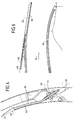
- Figure 1 shows a turboprop 1 suspended under wing 2 of an aircraft via a structure 3 called a "mast".
- the group 1 has a nacelle 4 completely surrounding a X-axis turbofan 5 with double flow.
- the nacelle 4 has at the front a air inlet 6 located upstream of the engine, and at the rear a nozzle ejection 7 whose outlet 8 is located downstream of the engine.
- the nozzle 7 allows the common ejection of the hot primary flow 9 passing through the engine and cold secondary flow 10 which circulates in the annular channel 11 delimited by the internal wall 12 of the nacelle 4 and the casing 13 of the engine.
- the primary flow 9 follows the usual cycle in the turbojet engine 5. It is first compressed by compressors, then it is used for combustion fuel in a combustion chamber. Hot gases from the combustion chamber are expanded in a high turbine pressure used to drive the compressors, and in a turbine low pressure which causes a blower 14 disposed at the front in the annular channel 11, and are ejected at the rear of the engine where they mix with cold secondary flow 10, thanks to a device mixer 15 surrounded by the nozzle 7.
- the nacelle 4 is made upstream downstream of four sections namely, at the front the air intake, followed by a body 16 surrounding the fan 14 and fixed vanes 17 which straighten the cold secondary flow 10 delivered by the blower 14, then a thrust reverser 20 disposed in the middle section of the nacelle 4, and finally the ejection nozzle 7 of the hot primary flow 9 and cold secondary flow 10.
- the thrust reverser 20, shown in Figures 1 and 9 is of the grid type, while that shown in Figure 2 is of the door type. These two types of reverser have in common openings radial 21 formed in the wall of the nacelle 4 and capable of being concealed by movable shutters 22, and means 23 for closing the annular channel 11 behind the radial openings 21.
- the radial openings 21 are formed between a front frame annular 24, and an annular rear frame 25 connected by beams longitudinal 26, the assembly forming a squirrel cage.
- the radial openings 21 include grids 27 intended to divert the secondary flow 10 towards the outside of the nacelle 4 and forward in "reverse jet” mode.
- the two frames 24 and 25 and the beams 26 are hollow structures to be rigid and light.
- the annular channel 11 When the thrust reverser 20 is in "direct jet” mode, the annular channel 11 is open, the radial openings 21 are closed by the movable shutters 22, so that the cold secondary flow 10 circulates in the annular channel 11 from front to back and ensures with the flow hot primary 9 the thrust of the turbojet engine 5.
- the nozzle 7 is in this case cooled by cold flow 10.
- the thrust reverser 20 When the thrust reverser 20 is in "reverse jet” mode, the radial openings 21 are open and the annular channel 11 is closed, so that the cold secondary flow 10 is directed outwards and towards the front of the nacelle 4 through the side openings 21, which produces reverse thrust intended to brake the airplane traveling on the ground.
- the "reverse jet” mode only the hot primary flow 9 passes through the nozzle 7, this which warms it up. But to effectively brake the plane, you have to request power from the turbojet 5, which increases the intensity and the temperature of the hot primary flow 9.
- the turboprop 1 comprises means for forming an air film against the internal wall 30 of the nozzle 7 cold 31 which cools it and isolates it from the hot primary flow 9 in particular by "reverse jet” mode.
- the front region of the nozzle 7 comprises between the internal wall 30 and external cowling 32 an annular enclosure 33 likely to receive cold air which communicates with the interior of the nozzle 7 downstream of the mixer 15 by a plurality of perforations 34 formed in the inner wall 30.
- Figures 2 to 7 show in detail a first form of embodiment of the invention applied to a door thrust reverser.
- the movable shutters 22 are constituted by pivotally mounted doors on two adjacent beams 26 at pivot means 40, such that in the "reverse jet” position the downstream portions 23 of the doors 22 close the annular channel 11, and deflects the secondary flow 10 towards the lateral openings 21 and towards the front of nacelle 4, as shown in dotted lines on the figure 3.
- the internal face 41 of the door 22 is equipped with a scoop 42, whose configuration is such that in the "reverse jet” position it allows take a flow of cold air sufficient to cool the nozzle 7.
- This flow air is led to the annular enclosure 33 of the nozzle 7 by a conduit flexible 43, which opens at one end into the internal cavity of the scoop 42, passes through a bore 44 formed in a pivot 40, partly accommodates in the internal cavity of the corresponding longitudinal beam 26 and opens out by the other end in the annular enclosure 33 of the nozzle 7.
- FIG 8 shows a second embodiment of the invention applied to a thrust reverser 20 with doors.
- Scoop 42 is here provided on the internal face of a beam 26 upstream of the portions rear 23 of the doors in "reverse jet” position.
- the air taken off by the scoop 42 is transmitted to the enclosure 33 of the nozzle 7 by a conduit 43 which, in the present case is not necessarily flexible.
- FIGS 9 to 11 show in detail an embodiment of the invention applied to a thrust reverser 20 of the grate type.
- the cooling air flow from the nozzle 7 is taken from the flow secondary 10 by means of a scoop 42 provided in the casing 13 of the turbojet 5 upstream of the flaps 23 which deflects the secondary flow 10 in the deployed position, and is brought towards the enclosure 33 of the nozzle 7 by a conduit 43 disposed in the casing 13 and by a conduit 44 formed in a radial arm 45 connecting the nozzle 7 to the casing 13 of the engine.
- FIG 12 shows another embodiment of the invention applied to a thrust reverser 20 with grids.
- Air flow cold of the nozzle 7 is here taken from the engine at a valve 50 for regulating the turbine clearance control device and the means to bring the air flow taken to the enclosure 33 of the nozzle include, as in the previous example, a conduit 43 arranged in the casing and a conduit 44 formed in a radial arm 45 connecting the nozzle 7 to the casing 13 of the engine.
- Air supplying the control device of the clearance is taken from the cold flow upstream of the reversing means of thrust, which ensures good circulation of cooling air from the nozzle in "reverse jet" mode, due to the pressure difference between the upstream and downstream of the reverse thrust means in this mode of operation.
Landscapes
- Engineering & Computer Science (AREA)
- Chemical & Material Sciences (AREA)
- Combustion & Propulsion (AREA)
- Mechanical Engineering (AREA)
- General Engineering & Computer Science (AREA)
- Structures Of Non-Positive Displacement Pumps (AREA)
- Supercharger (AREA)
- Jet Pumps And Other Pumps (AREA)
Abstract
Description
Claims (8)
- Turboréacteur à double flux comportant un moteur (5) d'axe X logeant complètement dans une nacelle (4) tubulaire dont la paroi interne (12) définit avec le carter (13) dudit moteur un passage annulaire (11) dans lequel s'écoule un flux secondaire (10) délivré par une soufflante (14), ladite nacelle (4) présentant une entrée d'air (6) en amont du moteur, des moyens d'inversion de poussée (20) dans sa section médiane et une tuyère commune (7) d'éjection du flux primaire (9) et du flux secondaire (10) dont la sortie (8) est située en aval du moteur, lesdits moyens d'inversion de poussée étant susceptibles de prendre une position active dans laquelle le flux secondaire (10) est dévié vers l'extérieur et vers l'avant de ladite nacelle, ladite tuyère (7) comportant une enceinte (33) délimitée par les parois interne (30) et externe (32) de ladite tuyère,
caractérisé par le fait qu'il comporte en outre des moyens pour refroidir la tuyère (7) lorsque les moyens d'inversion de poussée (20) sont dans la position active, lesdits moyens comportant des moyens de prélèvement (42) d'un débit d'air de refroidissement, dans le flux secondaire (10) en amont des moyens d'inversion de poussée (20), des moyens (43) pour amener le débit d'air prélevé dans l'enceinte (33) de ladite tuyère (7) et des moyens (34) pour former un film d'air (31) de refroidissement sur la face interne de ladite tuyère (7). - Turboréacteur selon la revendication 1, caractérisé par le fait que les moyens pour former un film d'air (31) sur la face interne de ladite tuyère (7) comportent une multiperforation (34) ménagée dans la paroi interne (30) de ladite tuyère (7).
- Turboréacteur selon l'une des revendications 1 ou 2, caractérisé par le fait que le débit d'air de refroidissement est prélevé dans le flux secondaire (10) au moyen d'au moins une écope (42).
- Turboréacteur selon la revendication 3, caractérisé par le fait que les moyens d'inversion (20) de poussée comportent au moins une porte (23) montée basculante sur des poutres longitudinales (26) de la nacelle (4) au moyen de pivots de support (40).
- Turboréacteur selon la revendication 4, caractérisé par le fait que l'écope (42) est prévue sur la face interne (41) de la porte (23), et les moyens pour amener le débit d'air prélevé dans l'enceinte (33) de la tuyère (7) comportent un conduit (43) reliant l'écope (42) à ladite enceinte (33) via un alésage (44) ménagé axialement dans un pivot de support (40) de ladite porte (23).
- Turboréacteur selon la revendication 4, caractérisé par le fait que l'écope (42) est prévue sur la face interne d'une poutre longitudinale (26) en amont des pivots de support (40) et les moyens pour amener le débit d'air prélevé dans l'enceinte (33) de la tuyère (7) comportent un conduit (43) reliant l'écope (42) à ladite enceinte (33).
- Turboréacteur selon la revendication 3, caractérisé par le fait que les moyens d'inversion (20) de poussée comportent des grilles fixes (27) susceptibles d'être masquées par des obturateurs (22) mobiles axialement, et des volets (23) basculants susceptibles de dévier le flux secondaire vers les grilles (27) en position déployée, l'écope (42) est prévue sur le carter (13) du moteur en amont des volets (23) en position déployée et les moyens pour amener le débit d'air prélevé dans l'enceinte (33) de la tuyère (7) comportent un conduit (43, 44) reliant l'écope à ladite enceinte via un bras radial (45) reliant la tuyère (7) au carter (13) du moteur.
- Turboréacteur selon la revendication 2, caractérisé par le fait que le débit d'air de refroidissement est prélevé sur le moteur au niveau d'une vanne (50) de régulation du dispositif de contrôle du jeu des turbines et les moyens pour amener le débit d'air prélevé dans l'enceinte de la tuyère comportent un conduit (43, 44) reliant ladite vanne à ladite enceinte (33) via un bras radial (45) reliant la tuyère (7) au carter (13) du moteur.
Applications Claiming Priority (2)
| Application Number | Priority Date | Filing Date | Title |
|---|---|---|---|
| FR0200234 | 2002-01-10 | ||
| FR0200234A FR2834533B1 (fr) | 2002-01-10 | 2002-01-10 | Dispositif de refroidissement de la tuyere commune sur une nacelle |
Publications (2)
| Publication Number | Publication Date |
|---|---|
| EP1327767A1 true EP1327767A1 (fr) | 2003-07-16 |
| EP1327767B1 EP1327767B1 (fr) | 2006-06-07 |
Family
ID=8871215
Family Applications (1)
| Application Number | Title | Priority Date | Filing Date |
|---|---|---|---|
| EP03290018A Expired - Lifetime EP1327767B1 (fr) | 2002-01-10 | 2003-01-06 | Dispositif de refroidissement de la tuyère commune sur une nacelle |
Country Status (6)
| Country | Link |
|---|---|
| US (1) | US6804947B2 (fr) |
| EP (1) | EP1327767B1 (fr) |
| CA (1) | CA2416251C (fr) |
| DE (1) | DE60305747T2 (fr) |
| ES (1) | ES2265091T3 (fr) |
| FR (1) | FR2834533B1 (fr) |
Cited By (3)
| Publication number | Priority date | Publication date | Assignee | Title |
|---|---|---|---|---|
| FR3019591A1 (fr) * | 2014-04-08 | 2015-10-09 | Aircelle Sa | Dispositif d’inversion de poussee a portes pour nacelle de turboreacteur d’aeronef |
| FR3097596A1 (fr) * | 2019-06-21 | 2020-12-25 | Safran Nacelles | Grille d’inverseur de poussée comprenant des canaux de refroidissement longitudinaux |
| EP3971401A1 (fr) * | 2020-05-05 | 2022-03-23 | Rohr, Inc. | Buse de système de propulsion d'aéronef comportant un passage d'écoulement interne |
Families Citing this family (21)
| Publication number | Priority date | Publication date | Assignee | Title |
|---|---|---|---|---|
| FR2873167B1 (fr) * | 2004-07-15 | 2007-11-02 | Hurel Hispano Sa | Dispositif de refroidissement de la tuyere primaire d'un turboreacteur a double flux |
| DE112005003683A5 (de) * | 2005-06-08 | 2008-05-29 | Birgit Bergmann | Ejektortriebwerk |
| US7311175B2 (en) * | 2005-08-10 | 2007-12-25 | United Technologies Corporation | Acoustic liner with bypass cooling |
| US7401682B2 (en) * | 2005-08-10 | 2008-07-22 | United Technologies Corporation | Architecture for an acoustic liner |
| US8015797B2 (en) | 2006-09-21 | 2011-09-13 | Jean-Pierre Lair | Thrust reverser nozzle for a turbofan gas turbine engine |
| US7735778B2 (en) | 2007-11-16 | 2010-06-15 | Pratt & Whitney Canada Corp. | Pivoting fairings for a thrust reverser |
| US8091827B2 (en) | 2007-11-16 | 2012-01-10 | The Nordam Group, Inc. | Thrust reverser door |
| US8051639B2 (en) | 2007-11-16 | 2011-11-08 | The Nordam Group, Inc. | Thrust reverser |
| US8172175B2 (en) | 2007-11-16 | 2012-05-08 | The Nordam Group, Inc. | Pivoting door thrust reverser for a turbofan gas turbine engine |
| US8052086B2 (en) | 2007-11-16 | 2011-11-08 | The Nordam Group, Inc. | Thrust reverser door |
| US8052085B2 (en) | 2007-11-16 | 2011-11-08 | The Nordam Group, Inc. | Thrust reverser for a turbofan gas turbine engine |
| US8127530B2 (en) | 2008-06-19 | 2012-03-06 | The Nordam Group, Inc. | Thrust reverser for a turbofan gas turbine engine |
| DE102010009477A1 (de) * | 2010-02-26 | 2011-09-01 | Rolls-Royce Deutschland Ltd & Co Kg | Fluggasturbinenantrieb |
| FR2962977B1 (fr) * | 2010-07-20 | 2012-08-17 | Airbus Operations Sas | Nacelle pour aeronef |
| US9046005B2 (en) * | 2013-04-03 | 2015-06-02 | General Electric Company | Gas turbine exhaust diffuser with helical turbulator |
| US20160245232A1 (en) * | 2015-02-19 | 2016-08-25 | Rohr, Inc. | Blocker Door Configuration for a Thrust Reverser of a Turbofan Engine |
| US9835092B2 (en) * | 2015-06-30 | 2017-12-05 | United Technologies Corporation | Seals for gas turbine engine nacelle cowlings |
| PL421120A1 (pl) | 2017-04-04 | 2018-10-08 | General Electric Company Polska Spolka Z Ograniczona Odpowiedzialnoscia | Silnik turbinowy i części składowe do stosowania w nim |
| US11098649B2 (en) * | 2018-07-19 | 2021-08-24 | The Boeing Company | Self-regulating back-side pressurization system for thermal insulation blankets |
| US11085398B2 (en) | 2019-03-12 | 2021-08-10 | Rohr, Inc. | Core air flow to equalize temperature differential |
| FR3094750B1 (fr) * | 2019-04-03 | 2021-11-26 | Safran Nacelles | Système de refroidissement de turboréacteur pour aéronef |
Citations (5)
| Publication number | Priority date | Publication date | Assignee | Title |
|---|---|---|---|---|
| GB1258331A (fr) * | 1968-03-28 | 1971-12-30 | ||
| US3826088A (en) * | 1973-02-01 | 1974-07-30 | Gen Electric | Gas turbine engine augmenter cooling liner stabilizers and supports |
| US3837411A (en) * | 1973-11-21 | 1974-09-24 | Gen Electric | Diverter valve for a gas turbine with an augmenter |
| FR2593237A1 (fr) * | 1986-01-17 | 1987-07-24 | Hispano Suiza Sa | Canal a flux froid d'inverseur de poussee de turboreacteur multiflux associe a des moyens combines de prelevements d'air |
| FR2717859A1 (fr) * | 1994-03-28 | 1995-09-29 | Sud Ouest Conception Aeronauti | Turbomoteur à double flux équipé d'un système d'inversion de poussée et d'un dispositif de restriction du canal d'éjection des gaz froids, et dispositif de restriction équipant un tel turbomoteur. |
Family Cites Families (2)
| Publication number | Priority date | Publication date | Assignee | Title |
|---|---|---|---|---|
| US3612402A (en) * | 1969-12-22 | 1971-10-12 | Rohr Corp | Thrust-controlling apparatus with variable axial flow area for differing flight regimes and thrust reversal |
| US4093122A (en) * | 1976-11-03 | 1978-06-06 | Rohr Industries, Inc. | Integrated divergent exhaust nozzle thrust reverser |
-
2002
- 2002-01-10 FR FR0200234A patent/FR2834533B1/fr not_active Expired - Fee Related
- 2002-12-31 US US10/331,643 patent/US6804947B2/en not_active Expired - Fee Related
-
2003
- 2003-01-06 EP EP03290018A patent/EP1327767B1/fr not_active Expired - Lifetime
- 2003-01-06 DE DE60305747T patent/DE60305747T2/de not_active Expired - Fee Related
- 2003-01-06 ES ES03290018T patent/ES2265091T3/es not_active Expired - Lifetime
- 2003-01-07 CA CA002416251A patent/CA2416251C/fr not_active Expired - Fee Related
Patent Citations (5)
| Publication number | Priority date | Publication date | Assignee | Title |
|---|---|---|---|---|
| GB1258331A (fr) * | 1968-03-28 | 1971-12-30 | ||
| US3826088A (en) * | 1973-02-01 | 1974-07-30 | Gen Electric | Gas turbine engine augmenter cooling liner stabilizers and supports |
| US3837411A (en) * | 1973-11-21 | 1974-09-24 | Gen Electric | Diverter valve for a gas turbine with an augmenter |
| FR2593237A1 (fr) * | 1986-01-17 | 1987-07-24 | Hispano Suiza Sa | Canal a flux froid d'inverseur de poussee de turboreacteur multiflux associe a des moyens combines de prelevements d'air |
| FR2717859A1 (fr) * | 1994-03-28 | 1995-09-29 | Sud Ouest Conception Aeronauti | Turbomoteur à double flux équipé d'un système d'inversion de poussée et d'un dispositif de restriction du canal d'éjection des gaz froids, et dispositif de restriction équipant un tel turbomoteur. |
Cited By (5)
| Publication number | Priority date | Publication date | Assignee | Title |
|---|---|---|---|---|
| FR3019591A1 (fr) * | 2014-04-08 | 2015-10-09 | Aircelle Sa | Dispositif d’inversion de poussee a portes pour nacelle de turboreacteur d’aeronef |
| WO2015155432A1 (fr) * | 2014-04-08 | 2015-10-15 | Aircelle | Dispositif d'inversion de poussée à portes pour nacelle de turboréacteur d'aéronef |
| US10605196B2 (en) | 2014-04-08 | 2020-03-31 | Aircelle | Door-type thrust reverser device for aircraft turbojet engine nacelle |
| FR3097596A1 (fr) * | 2019-06-21 | 2020-12-25 | Safran Nacelles | Grille d’inverseur de poussée comprenant des canaux de refroidissement longitudinaux |
| EP3971401A1 (fr) * | 2020-05-05 | 2022-03-23 | Rohr, Inc. | Buse de système de propulsion d'aéronef comportant un passage d'écoulement interne |
Also Published As
| Publication number | Publication date |
|---|---|
| EP1327767B1 (fr) | 2006-06-07 |
| FR2834533A1 (fr) | 2003-07-11 |
| US6804947B2 (en) | 2004-10-19 |
| ES2265091T3 (es) | 2007-02-01 |
| US20030140615A1 (en) | 2003-07-31 |
| DE60305747T2 (de) | 2006-10-05 |
| DE60305747D1 (de) | 2006-07-20 |
| CA2416251C (fr) | 2008-06-17 |
| CA2416251A1 (fr) | 2003-07-10 |
| FR2834533B1 (fr) | 2004-10-29 |
Similar Documents
| Publication | Publication Date | Title |
|---|---|---|
| CA2416251C (fr) | Dispositif de refroidissement de la tuyere commune sur une nacelle de turboreacteur | |
| EP1928737B1 (fr) | Turbomoteur a double flux pourvu d`un prerefroidisseur | |
| CA2328555C (fr) | Dispositif d'evacuation d'air chaud pour capot d'entree d'air de moteur a reaction, a circuit de degivrage | |
| CA2904311C (fr) | Dispositif de refroidissement pour un turbomoteur d'une nacelle d'aeronef | |
| CA2933353A1 (fr) | Turbomachine d'aeronef comportant un echangeur de chaleur du type pre-refroidisseur | |
| FR2689567A1 (fr) | Injecteur de carburant pour chambre de post-combustion d'une turbomachine. | |
| EP3732360B1 (fr) | Inverseur de poussée à grilles pour turboréacteur | |
| WO2014207408A1 (fr) | Dispositif de dégivrage et de conditionnement pour aéronef | |
| EP1365203B1 (fr) | Echangeur pour circuit de conditionnement d'air d'aéronef et ensemble de propulsion integrant un tel échangeur | |
| FR2694962A1 (fr) | Turboréacteur dont la chambre de combustion est protégée contre les effets d'une ingestion massive d'eau. | |
| EP2171218B1 (fr) | Turbomoteur a double flux et tuyere de flux chaud perfectionnee | |
| CA2925565A1 (fr) | Chambre de combustion de turbomachine pourvue de moyens de deflection d'air pour reduire le sillage cree par une bougie d'allumage | |
| EP1609719B1 (fr) | Procédé de freinage d'un avion et turboréacteur à double flux pour la mise en oeuvre du procédé | |
| FR3044636B1 (fr) | Turbomachine d'aeronef equipee d'un echangeur de chaleur surfacique air-huile | |
| EP4166771A1 (fr) | Ensemble propulsif pour aéronef | |
| EP4124738A1 (fr) | Ensemble propulsif pour aéronef | |
| FR2824598A1 (fr) | Dispositif de ventilation d'une nacelle du corps d'un turboreacteur | |
| WO2015145056A1 (fr) | Dispositif d'inversion de poussée sans grille pour nacelle de turboréacteur d'aéronef | |
| EP3728797B1 (fr) | Ensemble propulsif pour aéronef et procédé de ventilation d'une enceinte moteur | |
| FR3136016A1 (fr) | Anneau accroche-flammes pour postcombustion de turboreacteur comprenant un conduit pour chauffer un segment angulaire de l'anneau | |
| FR3122695A1 (fr) | Cône de diffusion à double paroi définissant un plenum de refroidissement pour partie arrière de turboréacteur | |
| WO2022223914A1 (fr) | Cone de diffusion pour partie arriere de turboreacteur integrant un anneau accroche-flamme en bord de fuite | |
| EP4327022A1 (fr) | Dispositif d'injection de carburant pour postcombustion de turboreacteur | |
| FR2904664A1 (fr) | Moteur a turbine a gaz a dispositif de post-combustion | |
| WO2018215718A1 (fr) | Aube pour turbine de turbomachine comprenant des cavites internes de circulation d'air de refroidissement |
Legal Events
| Date | Code | Title | Description |
|---|---|---|---|
| PUAI | Public reference made under article 153(3) epc to a published international application that has entered the european phase |
Free format text: ORIGINAL CODE: 0009012 |
|
| AK | Designated contracting states |
Designated state(s): AT BE BG CH CY CZ DE DK EE ES FI FR GB GR HU IE IT LI LU MC NL PT SE SI SK TR |
|
| AX | Request for extension of the european patent |
Extension state: AL LT LV MK RO |
|
| RIN1 | Information on inventor provided before grant (corrected) |
Inventor name: LE DOCTE, THIERRY JACQUES Inventor name: VICOGNE, LAURENT MARCEL |
|
| 17P | Request for examination filed |
Effective date: 20031006 |
|
| AKX | Designation fees paid |
Designated state(s): DE ES FR GB IT |
|
| RAP1 | Party data changed (applicant data changed or rights of an application transferred) |
Owner name: AIRCELLE |
|
| GRAP | Despatch of communication of intention to grant a patent |
Free format text: ORIGINAL CODE: EPIDOSNIGR1 |
|
| GRAS | Grant fee paid |
Free format text: ORIGINAL CODE: EPIDOSNIGR3 |
|
| GRAA | (expected) grant |
Free format text: ORIGINAL CODE: 0009210 |
|
| AK | Designated contracting states |
Kind code of ref document: B1 Designated state(s): DE ES FR GB IT |
|
| PG25 | Lapsed in a contracting state [announced via postgrant information from national office to epo] |
Ref country code: IT Free format text: LAPSE BECAUSE OF FAILURE TO SUBMIT A TRANSLATION OF THE DESCRIPTION OR TO PAY THE FEE WITHIN THE PRESCRIBED TIME-LIMIT;WARNING: LAPSES OF ITALIAN PATENTS WITH EFFECTIVE DATE BEFORE 2007 MAY HAVE OCCURRED AT ANY TIME BEFORE 2007. THE CORRECT EFFECTIVE DATE MAY BE DIFFERENT FROM THE ONE RECORDED. Effective date: 20060607 |
|
| REG | Reference to a national code |
Ref country code: GB Ref legal event code: FG4D Free format text: NOT ENGLISH |
|
| GBT | Gb: translation of ep patent filed (gb section 77(6)(a)/1977) |
Effective date: 20060607 |
|
| REF | Corresponds to: |
Ref document number: 60305747 Country of ref document: DE Date of ref document: 20060720 Kind code of ref document: P |
|
| REG | Reference to a national code |
Ref country code: ES Ref legal event code: FG2A Ref document number: 2265091 Country of ref document: ES Kind code of ref document: T3 |
|
| PLBE | No opposition filed within time limit |
Free format text: ORIGINAL CODE: 0009261 |
|
| STAA | Information on the status of an ep patent application or granted ep patent |
Free format text: STATUS: NO OPPOSITION FILED WITHIN TIME LIMIT |
|
| 26N | No opposition filed |
Effective date: 20070308 |
|
| PGFP | Annual fee paid to national office [announced via postgrant information from national office to epo] |
Ref country code: ES Payment date: 20090122 Year of fee payment: 7 |
|
| PGFP | Annual fee paid to national office [announced via postgrant information from national office to epo] |
Ref country code: DE Payment date: 20090112 Year of fee payment: 7 |
|
| PGFP | Annual fee paid to national office [announced via postgrant information from national office to epo] |
Ref country code: GB Payment date: 20090109 Year of fee payment: 7 |
|
| PGFP | Annual fee paid to national office [announced via postgrant information from national office to epo] |
Ref country code: FR Payment date: 20081215 Year of fee payment: 7 |
|
| GBPC | Gb: european patent ceased through non-payment of renewal fee |
Effective date: 20100106 |
|
| REG | Reference to a national code |
Ref country code: FR Ref legal event code: ST Effective date: 20100930 |
|
| PG25 | Lapsed in a contracting state [announced via postgrant information from national office to epo] |
Ref country code: FR Free format text: LAPSE BECAUSE OF NON-PAYMENT OF DUE FEES Effective date: 20100201 |
|
| PG25 | Lapsed in a contracting state [announced via postgrant information from national office to epo] |
Ref country code: DE Free format text: LAPSE BECAUSE OF NON-PAYMENT OF DUE FEES Effective date: 20100803 |
|
| PG25 | Lapsed in a contracting state [announced via postgrant information from national office to epo] |
Ref country code: GB Free format text: LAPSE BECAUSE OF NON-PAYMENT OF DUE FEES Effective date: 20100106 |
|
| REG | Reference to a national code |
Ref country code: ES Ref legal event code: FD2A Effective date: 20110328 |
|
| PG25 | Lapsed in a contracting state [announced via postgrant information from national office to epo] |
Ref country code: ES Free format text: LAPSE BECAUSE OF NON-PAYMENT OF DUE FEES Effective date: 20110315 |
|
| PG25 | Lapsed in a contracting state [announced via postgrant information from national office to epo] |
Ref country code: ES Free format text: LAPSE BECAUSE OF NON-PAYMENT OF DUE FEES Effective date: 20100107 |