EP1327767A1 - Cooling device for a common nozzle of a turbofan engine - Google Patents
Cooling device for a common nozzle of a turbofan engine Download PDFInfo
- Publication number
- EP1327767A1 EP1327767A1 EP03290018A EP03290018A EP1327767A1 EP 1327767 A1 EP1327767 A1 EP 1327767A1 EP 03290018 A EP03290018 A EP 03290018A EP 03290018 A EP03290018 A EP 03290018A EP 1327767 A1 EP1327767 A1 EP 1327767A1
- Authority
- EP
- European Patent Office
- Prior art keywords
- nozzle
- flow
- enclosure
- scoop
- nacelle
- Prior art date
- Legal status (The legal status is an assumption and is not a legal conclusion. Google has not performed a legal analysis and makes no representation as to the accuracy of the status listed.)
- Granted
Links
Images


Classifications
-
- F—MECHANICAL ENGINEERING; LIGHTING; HEATING; WEAPONS; BLASTING
- F02—COMBUSTION ENGINES; HOT-GAS OR COMBUSTION-PRODUCT ENGINE PLANTS
- F02K—JET-PROPULSION PLANTS
- F02K1/00—Plants characterised by the form or arrangement of the jet pipe or nozzle; Jet pipes or nozzles peculiar thereto
- F02K1/54—Nozzles having means for reversing jet thrust
- F02K1/64—Reversing fan flow
-
- F—MECHANICAL ENGINEERING; LIGHTING; HEATING; WEAPONS; BLASTING
- F02—COMBUSTION ENGINES; HOT-GAS OR COMBUSTION-PRODUCT ENGINE PLANTS
- F02K—JET-PROPULSION PLANTS
- F02K1/00—Plants characterised by the form or arrangement of the jet pipe or nozzle; Jet pipes or nozzles peculiar thereto
- F02K1/78—Other construction of jet pipes
- F02K1/82—Jet pipe walls, e.g. liners
- F02K1/822—Heat insulating structures or liners, cooling arrangements, e.g. post combustion liners; Infra-red radiation suppressors
-
- Y—GENERAL TAGGING OF NEW TECHNOLOGICAL DEVELOPMENTS; GENERAL TAGGING OF CROSS-SECTIONAL TECHNOLOGIES SPANNING OVER SEVERAL SECTIONS OF THE IPC; TECHNICAL SUBJECTS COVERED BY FORMER USPC CROSS-REFERENCE ART COLLECTIONS [XRACs] AND DIGESTS
- Y02—TECHNOLOGIES OR APPLICATIONS FOR MITIGATION OR ADAPTATION AGAINST CLIMATE CHANGE
- Y02T—CLIMATE CHANGE MITIGATION TECHNOLOGIES RELATED TO TRANSPORTATION
- Y02T50/00—Aeronautics or air transport
- Y02T50/60—Efficient propulsion technologies, e.g. for aircraft
Abstract
Description
L'invention concerne le domaine des turboréacteurs à double flux équipant des aéronefs subsoniques et comportant une nacelle longue terminée par une tuyère commune d'éjection du flux primaire et du flux secondaire.The invention relates to the field of twin turbojets flux equipping subsonic aircraft and comprising a long nacelle terminated by a common ejection nozzle for the primary flow and the flow secondary.
L'invention concerne plus précisément un turboréacteur d'axe X logeant complètement dans une nacelle tubulaire dont la paroi interne définit avec le carter dudit moteur un passage annulaire dans lequel s'écoule un flux secondaire délivré par une soufflante, ladite nacelle présentant une entrée d'air en amont du moteur, des moyens d'inversion de poussée dans sa section médiane et une tuyère commune d'éjection du flux primaire et du flux secondaire dont la sortie est située en aval du moteur, lesdits moyens d'inversion de poussée étant susceptibles de prendre une position active dans laquelle le flux secondaire est dévié vers l'extérieur et vers l'avant de ladite nacelle, et ladite tuyère comportant une enceinte délimitée par les parois interne et externe de ladite tuyère.The invention relates more precisely to an X-axis turbojet completely housed in a tubular nacelle whose internal wall defines with the casing of said motor an annular passage in which flows a secondary flow delivered by a blower, said nacelle having an air inlet upstream of the engine, reversing means thrust in its middle section and a common nozzle for ejecting the primary flow and secondary flow whose outlet is located downstream of the engine, said thrust reversing means being capable of take an active position in which the secondary flow is diverted towards the outside and towards the front of said nacelle, and said nozzle comprising a enclosure delimited by the internal and external walls of said nozzle.
L'extrémité aval du carter du moteur qui sépare la veine du flux primaire chaud de la veine du flux secondaire froid est équipée d'un mélangeur dont le but est d'accélérer le mélange des deux flux chaud et froid, afin de diminuer la vitesse des gaz éjectés par la tuyère commune, ce qui améliore le rendement propulsif et réduit le bruit de jet.The downstream end of the motor housing which separates the flow stream hot primary from the cold secondary flow vein is equipped with a mixer whose purpose is to accelerate the mixing of the two hot streams and cold, in order to reduce the speed of the gases ejected from the common nozzle, which improves propulsion efficiency and reduces jet noise.
En régime de croisière ou de plein gaz, les moyens d'inversion de poussée sont inopérants. Tout le débit d'air circulant dans la veine secondaire est éjecté par la tuyère commune en même temps que les gaz chauds du flux primaire et la paroi interne de la tuyère est léchée par de l'air froid. Ce mode de fonctionnement est appelé mode "jet direct".In cruising or full throttle mode, the means of reversing thrust are inoperative. All the air flow circulating in the vein secondary is ejected by the common nozzle together with the gases the primary flow and the internal wall of the nozzle is licked by cold air. This operating mode is called "direct jet" mode.
En revanche en mode "jet inversé", les moyens d'inversion de poussée obturent la veine secondaire, et le flux secondaire est dévié vers l'extérieur et vers l'avant de la nacelle, et seuls les gaz chauds de la veine primaire passent par la tuyère d'éjection. La tuyère est alors soumise à de fortes températures. Le mode "jet inversé" est utilisé uniquement pour assurer le freinage de l'aéronef après son atterrissage, et, pour freiner efficacement l'aéronef, il faut demander de la puissance au turboréacteur, ce qui augmente l'intensité et la température du flux chaud éjecté par la tuyère. C'est pourquoi, la tuyère commune doit être réalisée en un matériau résistant à la chaleur du seul flux chaud, tel que le titane, ce qui augmente à la fois sa masse et son coût. On the other hand, in "reverse jet" mode, the means of inversion of thrust obturates the secondary vein, and the secondary flow is diverted towards outside and towards the front of the pod, and only hot gases from the vein primary pass through the exhaust nozzle. The nozzle is then subjected to high temperatures. The "reverse jet" mode is used only for braking the aircraft after landing, and for braking the aircraft efficiently, you need to ask the turbojet for power, which increases the intensity and the temperature of the hot stream ejected by the nozzle. Therefore, the common nozzle must be produced in one heat-resistant material from the hot stream alone, such as titanium, which increases both its mass and its cost.
US 3 826 088 concerne un turboréacteur à usage militaire, non équipé de moyens d'inversion de poussée. La tuyère de ce turboréacteur entoure une chemise de protection thermique d'une chambre de post-combustion, et délimite avec cette dernière un canal annulaire continuellement alimenté par une partie du flux froid. La chemise comporte des fentes délivrant en permanence un film d'air sur sa face interne. Cette chemise n'est évidemment pas un élément structural de la tuyère, car elle doit pouvoir se dilater librement en fonction des variations des températures régnant dans la chambre de post-combustion.US 3,826,088 relates to a turbojet engine for military use, not equipped with thrust reversing means. The nozzle of this turbojet surrounds a thermal protection jacket of an post-combustion chamber, and defines therewith an annular channel continuously fed by part of the cold flow. Shirt has slots permanently delivering an air film on its face internal. This shirt is obviously not a structural element of the nozzle, because it must be able to expand freely according to variations temperatures prevailing in the post-combustion chamber.
FR 2 593 237 divulgue un dispositif de prélèvement d'air dans le flux froid d'un moteur à doubler flux avec inverseur de poussée, ce prélèvement d'air étant destiné au refroidissement, à la pressuration ou à la ventilation de l'avion. Mais ce document ne mentionne pas et ne suggère pas le refroidissement de la tuyère en mode de fonctionnement « jet inversé », dans un turboréacteur à double flux.FR 2,593,237 discloses an air sampling device in the cold flow of a double flow motor with thrust reverser, this air sample being intended for cooling, pressuring or ventilation of the aircraft. But this document does not mention and does not not suggest cooling of the nozzle in operating mode "Reverse jet", in a turbofan engine.
Le but de l'invention est de proposer un turboréacteur tel que mentionné en introduction dans lequel la tuyère d'éjection peut être réalisée dans un matériau moins dense.The object of the invention is to propose a turbojet engine such as mentioned in the introduction in which the ejection nozzle can be made of a less dense material.
Le but est atteint selon l'invention par le fait que le turboréacteur proposé comporte en outre des moyens pour refroidir la tuyère lorsque les moyens d'inversion de poussée sont dans la position active, lesdits moyens comportant des moyens de prélèvement d'un débit d'air de refroidissement, dans le flux secondaire en amont des moyens d'inversion de poussée, des moyens pour amener le débit d'air prélevé dans l'enceinte de ladite tuyère et des moyens pour former un film d'air de refroidissement sur la face interne de ladite tuyère.The object is achieved according to the invention by the fact that the The proposed turbojet engine further comprises means for cooling the nozzle when the thrust reversing means are in the position active, said means comprising means for withdrawing a flow rate cooling air, in the secondary flow upstream of the means reverse thrust, means for bringing the air flow rate in the enclosure of said nozzle and means for forming an air film of cooling on the internal face of said nozzle.
L'invention exploite ainsi l'écart de pression entre l'amont et l'aval des volets en mode « jet inversé » pour faire circuler l'air prélevé dans le dispositif de refroidissement. La surpression dans le flux secondaire en amont des moyens d'inversion de poussée provient de la rotation du fan et de l'air qui s'engouffre dans l'entrée d'air du turboréacteur sous l'effet de la vitesse de l'avion. La dépression en aval des moyens d'inversion de poussée provient de l'effet aspiration dans la tuyère commune sous l'effet également de la vitesse de l'avion. The invention thus exploits the pressure difference between the upstream and the downstream of the flaps in "reverse jet" mode to circulate the sampled air in the cooling device. Overpressure in the flow secondary upstream of the thrust reversal means comes from the rotation of the fan and the air rushing into the air intake of the turbojet engine under the effect of the speed of the aircraft. Downstream depression thrust reversal means comes from the suction effect in the common nozzle also under the effect of the speed of the aircraft.
Le fait que, grâce à l'invention, la tuyère soit refroidie en mode « jet inversé », elle peut être réalisée dans un matériau moins dense et moins coûteux.The fact that, thanks to the invention, the nozzle is cooled in "Reverse jet", it can be made in a less dense material and cheaper.
Avantageusement, les moyens pour former un film d'air sur la face interne de la tuyère comportent une multiperforation ménagée dans la paroi interne de ladite tuyère.Advantageously, the means for forming an air film on the internal face of the nozzle have a multi-perforation formed in the internal wall of said nozzle.
Selon un premier mode de réalisation de l'invention, le débit d'air de refroidissement est prélevé dans le flux secondaire au moyen d'au moins une écope.According to a first embodiment of the invention, the flow cooling air is taken from the secondary flow by means of minus one scoop.
Lorsque les moyens d'inversion de poussée comportent au moins une porte montée basculante sur des poutres longitudinales de la nacelle au moyen de pivots de support, et selon une première forme de réalisation de l'invention, l'écope est prévue sur la face interne de la porte, et les moyens pour amener le débit d'air prélevé dans l'enceinte de la tuyère comportent un conduit reliant l'écope à ladite enceinte via un alésage ménagé axialement dans un pivot de support de ladite porte.When the thrust reversing means include minus a swinging door mounted on longitudinal beams of the nacelle by means of support pivots, and according to a first form of embodiment of the invention, the scoop is provided on the internal face of the door, and the means for bringing the air flow taken from the enclosure of the nozzle have a conduit connecting the scoop to said enclosure via a bore axially arranged in a support pivot of said door.
Selon une deuxième forme de réalisation de l'invention, l'écope est prévue sur la face interne d'une poutre longitudinale en amont des pivots de support et les moyens pour amener le débit prélevé dans l'enceinte de la tuyère comportent un conduit reliant l'écope à ladite enceinte.According to a second embodiment of the invention, the scoop is provided on the internal face of a longitudinal beam upstream of the support pivots and the means for bringing the flow rate withdrawn into the enclosure of the nozzle comprise a conduit connecting the scoop to said pregnant.
Lorsque les moyens d'inversion de poussée comportent des grilles fixes susceptibles d'être masquées par des obturateurs mobiles axialement, et des volets basculants susceptibles de dévier le flux secondaire vers les grilles en position déployée, l'écope est prévue sur le carter du moteur en amont des volets en position déployée, et les moyens pour amener dans l'enceinte de la tuyère le débit d'air prélevé comportent un conduit reliant l'écope à ladite enceinte via un bras radial reliant la tuyère au carter du moteur.When the thrust reversing means include fixed grids capable of being masked by movable shutters axially, and tilting flaps capable of diverting the flow secondary towards the gates in the deployed position, the scoop is provided on the motor housing upstream of the flaps in the deployed position, and the means to bring the withdrawn air flow into the nozzle enclosure a conduit connecting the scoop to said enclosure via a radial arm connecting the nozzle to the motor housing.
Dans tous les cas, la géométrie et la position de l'écope sont calculées de telle manière que l'écope ne perturbe pas outre mesure l'écoulement du flux secondaire en mode "jet direct", et de telle manière que, en mode "jet inversé", la pression de l'air dans l'écope soit suffisante pour assurer le prélèvement d'un débit d'air suffisant pour le refroidissement de la tuyère. In all cases, the geometry and position of the scoop are calculated in such a way that the scoop does not disturb unduly the flow of the secondary flow in "direct jet" mode, and in such a way that, in "reverse jet" mode, the air pressure in the scoop is sufficient to ensure that sufficient air flow is taken for the cooling of the nozzle.
Selon un deuxième mode de réalisation de l'invention, le débit d'air de refroidissement est prélevé sur le moteur au niveau du dispositif de contrôle du jeu des turbines et les moyens pour amener dans l'enceinte de la tuyère le débit d'air prélevé comportent un conduit reliant une vanne de régulation dudit dispositif de contrôle de jeu à ladite enceinte via un bras radial reliant la tuyère au carter du moteur.According to a second embodiment of the invention, the flow cooling air is taken from the engine at the device for checking the play of the turbines and the means for bringing them into the enclosure from the nozzle the air flow taken off comprises a duct connecting a valve regulating said game control device to said enclosure via a radial arm connecting the nozzle to the engine casing.
D'autres caractéristiques et avantages de l'invention ressortiront
à la lecture de la description suivante faite à titre d'exemple et en
référence aux dessins annexés dans lesquels :
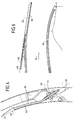
La figure 1 montre un groupe turbopropulseur 1 suspendu sous
l'aile 2 d'un avion par l'intermédiaire d'une structure 3 appelée "mât". Le
groupe 1 comporte une nacelle 4 entourant complètement un
turboréacteur 5 à double flux d'axe X. La nacelle 4 comporte à l'avant une
entrée d'air 6 située en amont du moteur, et à l'arrière une tuyère
d'éjection 7 dont la sortie 8 est située en aval du moteur. La tuyère 7
permet l'éjection commune du flux primaire chaud 9 traversant le moteur
et du flux secondaire froid 10 qui circule dans le canal annulaire 11
délimité par la paroi interne 12 de la nacelle 4 et le carter 13 du moteur.Figure 1 shows a turboprop 1 suspended under
Le flux primaire 9 suit dans le turboréacteur 5 le cycle habituel.
Il est d'abord comprimé par des compresseurs, puis il sert à la combustion
d'un carburant dans une chambre de combustion. Les gaz chauds issus de
la chambre de combustion sont détendus dans une turbine à haute
pression servant à entraíner les compresseurs, et dans une turbine à
basse pression qui entraíne une soufflante 14 disposée à l'avant dans le
canal annulaire 11, et sont éjectés à l'arrière du moteur où ils se
mélangent avec le flux secondaire froid 10, grâce à un dispositif
mélangeur 15 entouré par la tuyère 7.The
La nacelle 4 est constituée d'amont en aval de quatre tronçons
à savoir, à l'avant l'entrée d'air, suivie d'un corps 16 entourant la
soufflante 14 et les aubes fixes 17 qui redressent le flux secondaire froid
10 délivré par la soufflante 14, puis un inverseur de poussée 20 disposé
dans la section médiane de la nacelle 4, et enfin la tuyère d'éjection 7 du
flux primaire chaud 9 et du flux secondaire froid 10.The
L'inverseur de poussée 20, montrée sur les figures 1 et 9 est du
type à grilles, tandis que celui montré sur la figure 2 est du type à portes.
Ces deux types d'inverseur comportent en commun des ouvertures
radiales 21 ménagées dans la paroi de la nacelle 4 et susceptibles d'être
occultées par des obturateurs mobiles 22, et des moyens 23 pour fermer
le canal annulaire 11 à l'arrière des ouvertures radiales 21.The thrust reverser 20, shown in Figures 1 and 9 is of the
grid type, while that shown in Figure 2 is of the door type.
These two types of reverser have in common openings
radial 21 formed in the wall of the
Les ouvertures radiales 21 sont ménagées entre un cadre avant
annulaire 24, et un cadre arrière annulaire 25 reliés par des poutres
longitudinales 26, l'ensemble formant une cage d'écureuil. Lorsque
l'inverseur est du type à grilles, les ouvertures radiales 21 comportent des
grilles 27 destinées à dévier le flux secondaire 10 vers l'extérieur de la
nacelle 4 et vers l'avant en mode "jet inversé". Les deux cadres 24 et 25
et les poutres 26 sont des structures creuses pour être rigides et légères.The
Lorsque l'inverseur de poussée 20 est en mode "jet direct", le
canal annulaire 11 est ouvert, les ouvertures radiales 21 sont obturées par
les obturateurs mobiles 22, de sorte que le flux secondaire froid 10 circule
dans le canal annulaire 11 de l'avant vers l'arrière et assure avec le flux
primaire chaud 9 la poussée du turboréacteur 5. La tuyère 7 est dans ce
cas refroidie par le flux froid 10.When the
Lorsque l'inverseur de poussée 20 est en mode "jet inversé", les
ouvertures radiales 21 sont ouvertes et le canal annulaire 11 est fermé, de
sorte que le flux secondaire froid 10 est dirigé vers l'extérieur et vers
l'avant de la nacelle 4 par les ouvertures latérales 21, ce qui produit
l'inversion de poussée destinée à freiner l'avion roulant sur le sol. Dans le
mode "jet inversé", seul le flux primaire chaud 9 passe par la tuyère 7, ce
qui réchauffe cette dernière. Or pour freiner efficacement l'avion, il faut
demander de la puissance au turboréacteur 5, ce qui augmente l'intensité
et la température du flux primaire chaud 9.When the
Selon l'invention, le groupe turbopropulseur 1 comporte des
moyens pour former contre la paroi interne 30 de la tuyère 7 un film d'air
froid 31 qui la refroidit et l'isole du flux primaire chaud 9 notamment en
mode "jet inversé".According to the invention, the turboprop 1 comprises
means for forming an air film against the
A cet effet, la région avant de la tuyère 7 comporte entre la
paroi interne 30 et le capotage externe 32 une enceinte annulaire 33
susceptible de recevoir de l'air froid qui communique avec l'intérieur de la
tuyère 7 en aval du mélangeur 15 par une pluralité de perforations 34
ménagées dans la paroi interne 30.For this purpose, the front region of the
Les figures 2 à 7 montrent en détail une première forme de
réalisation de l'invention appliquée à un inverseur de poussée à portes.
Dans ce mode de réalisation, les obturateurs mobiles 22 sont constitués
par des portes montées pivotantes sur deux poutres adjacentes 26 au
moyen de pivots 40, de telle manière que dans la position "jet inversé"
les portions aval 23 des portes 22 viennent fermer le canal annulaire 11,
et dévient le flux secondaire 10 vers les ouvertures latérales 21 et vers
l'avant de la nacelle 4, ainsi que cela est montré en pointillé sur la
figure 3.Figures 2 to 7 show in detail a first form of
embodiment of the invention applied to a door thrust reverser.
In this embodiment, the
La face interne 41 de la porte 22 est équipée d'une écope 42,
dont la configuration est telle qu'en position "jet inversé" elle permet de
prélever un débit d'air froid suffisant pour refroidir la tuyère 7. Ce débit
d'air est conduit vers l'enceinte annulaire 33 de la tuyère 7 par un conduit
flexible 43, qui débouche à une extrémité dans la cavité interne de l'écope
42, passe par un alésage 44 ménagé dans un pivot 40, loge en partie dans
la cavité interne de la poutre longitudinale correspondante 26 et débouche
par l'autre extrémité dans l'enceinte annulaire 33 de la tuyère 7.The
La figure 8 montre une deuxième forme de réalisation de
l'invention appliquée à un inverseur de poussée 20 à portes. L'écope 42
est ici prévue sur la face interne d'une poutre 26 en amont des portions
arrière 23 des portes en position "jet inversé". L'air prélevé par l'écope 42
est transmis vers l'enceinte 33 de la tuyère 7 par un conduit 43 qui, dans
le cas présent, n'est pas nécessairement flexible.Figure 8 shows a second embodiment of
the invention applied to a
Les figures 9 à 11 montrent en détail une forme de réalisation
de l'invention appliquée à un inverseur de poussée 20 de type à grilles. Le
débit d'air de refroidissement de la tuyère 7 est prélevé dans le flux
secondaire 10 au moyen d'une écope 42 prévue dans le carter 13 du
turboréacteur 5 en amont des volets 23 qui dévient le flux secondaire 10
en position déployée, et est amené vers l'enceinte 33 de la tuyère 7 par
un conduit 43 disposé dans le carter 13 et par un conduit 44 ménagé dans
un bras radial 45 reliant la tuyère 7 au carter 13 du moteur.Figures 9 to 11 show in detail an embodiment
of the invention applied to a
La figure 12 montre une autre forme de réalisation de
l'invention appliquée à un inverseur de poussée 20 à grilles. Le débit d'air
froid de la tuyère 7 est ici prélevé sur le moteur au niveau d'une vanne 50
de régulation du dispositif de contrôle du jeu des turbines et les moyens
pour amener le débit d'air prélevé vers l'enceinte 33 de la tuyère
comportent, comme dans l'exemple précédent, un conduit 43 disposé
dans le carter et un conduit 44 ménagé dans un bras radial 45 reliant la
tuyère 7 au carter 13 du moteur. L'air alimentant le dispositif de contrôle
du jeu est prélevé dans le flux froid en amont des moyens d'inversion de
poussée, ce qui assure une bonne circulation de l'air de refroidissement de
la tuyère en mode « jet inversé », du fait de l'écart de pression entre
l'amont et l'aval des moyens d'inversion de poussée dans ce mode de
fonctionnement.Figure 12 shows another embodiment of
the invention applied to a
Claims (8)
caractérisé par le fait qu'il comporte en outre des moyens pour refroidir la tuyère (7) lorsque les moyens d'inversion de poussée (20) sont dans la position active, lesdits moyens comportant des moyens de prélèvement (42) d'un débit d'air de refroidissement, dans le flux secondaire (10) en amont des moyens d'inversion de poussée (20), des moyens (43) pour amener le débit d'air prélevé dans l'enceinte (33) de ladite tuyère (7) et des moyens (34) pour former un film d'air (31) de refroidissement sur la face interne de ladite tuyère (7).Double-flow turbojet engine comprising an X-axis motor (5) completely accommodating in a tubular nacelle (4) whose internal wall (12) defines with the casing (13) of said motor an annular passage (11) in which flows a secondary flow (10) delivered by a blower (14), said nacelle (4) having an air inlet (6) upstream of the engine, thrust reversing means (20) in its middle section and a nozzle common (7) for ejecting the primary flow (9) and the secondary flow (10) whose outlet (8) is located downstream of the engine, said thrust reversing means being capable of assuming an active position in which the secondary flow (10) is deflected towards the outside and towards the front of said nacelle, said nozzle (7) comprising an enclosure (33) delimited by the internal (30) and external (32) walls of said nozzle,
characterized in that it further comprises means for cooling the nozzle (7) when the thrust reversing means (20) are in the active position, said means comprising means for taking off (42) of a flow rate of cooling air, in the secondary flow (10) upstream of the thrust reversing means (20), means (43) for bringing the air flow taken from the enclosure (33) of said nozzle ( 7) and means (34) for forming a film of cooling air (31) on the internal face of said nozzle (7).
Applications Claiming Priority (2)
| Application Number | Priority Date | Filing Date | Title |
|---|---|---|---|
| FR0200234A FR2834533B1 (en) | 2002-01-10 | 2002-01-10 | DEVICE FOR COOLING THE COMMON NOZZLE ON A NACELLE |
| FR0200234 | 2002-01-10 |
Publications (2)
| Publication Number | Publication Date |
|---|---|
| EP1327767A1 true EP1327767A1 (en) | 2003-07-16 |
| EP1327767B1 EP1327767B1 (en) | 2006-06-07 |
Family
ID=8871215
Family Applications (1)
| Application Number | Title | Priority Date | Filing Date |
|---|---|---|---|
| EP03290018A Expired - Lifetime EP1327767B1 (en) | 2002-01-10 | 2003-01-06 | Cooling device for a common nozzle of a turbofan engine |
Country Status (6)
| Country | Link |
|---|---|
| US (1) | US6804947B2 (en) |
| EP (1) | EP1327767B1 (en) |
| CA (1) | CA2416251C (en) |
| DE (1) | DE60305747T2 (en) |
| ES (1) | ES2265091T3 (en) |
| FR (1) | FR2834533B1 (en) |
Cited By (3)
| Publication number | Priority date | Publication date | Assignee | Title |
|---|---|---|---|---|
| FR3019591A1 (en) * | 2014-04-08 | 2015-10-09 | Aircelle Sa | DEVICE FOR PUSH REVERSING WITH DOORS FOR AIRCRAFT TURBOKARATOR NACELLE |
| FR3097596A1 (en) * | 2019-06-21 | 2020-12-25 | Safran Nacelles | Thrust reverser grille including longitudinal cooling channels |
| EP3971401A1 (en) * | 2020-05-05 | 2022-03-23 | Rohr, Inc. | Aircraft propulsion system nozzle with internal flow passage |
Families Citing this family (21)
| Publication number | Priority date | Publication date | Assignee | Title |
|---|---|---|---|---|
| FR2873167B1 (en) * | 2004-07-15 | 2007-11-02 | Hurel Hispano Sa | DEVICE FOR COOLING THE PRIMARY PIPE OF A DOUBLE FLOW TURBOJETACTOR |
| DE112005003683A5 (en) * | 2005-06-08 | 2008-05-29 | Birgit Bergmann | Ejektortriebwerk |
| US7311175B2 (en) * | 2005-08-10 | 2007-12-25 | United Technologies Corporation | Acoustic liner with bypass cooling |
| US7401682B2 (en) * | 2005-08-10 | 2008-07-22 | United Technologies Corporation | Architecture for an acoustic liner |
| US8015797B2 (en) | 2006-09-21 | 2011-09-13 | Jean-Pierre Lair | Thrust reverser nozzle for a turbofan gas turbine engine |
| US8172175B2 (en) | 2007-11-16 | 2012-05-08 | The Nordam Group, Inc. | Pivoting door thrust reverser for a turbofan gas turbine engine |
| US8091827B2 (en) | 2007-11-16 | 2012-01-10 | The Nordam Group, Inc. | Thrust reverser door |
| US8052085B2 (en) | 2007-11-16 | 2011-11-08 | The Nordam Group, Inc. | Thrust reverser for a turbofan gas turbine engine |
| US8052086B2 (en) | 2007-11-16 | 2011-11-08 | The Nordam Group, Inc. | Thrust reverser door |
| US7735778B2 (en) | 2007-11-16 | 2010-06-15 | Pratt & Whitney Canada Corp. | Pivoting fairings for a thrust reverser |
| US8051639B2 (en) | 2007-11-16 | 2011-11-08 | The Nordam Group, Inc. | Thrust reverser |
| US8127530B2 (en) | 2008-06-19 | 2012-03-06 | The Nordam Group, Inc. | Thrust reverser for a turbofan gas turbine engine |
| DE102010009477A1 (en) * | 2010-02-26 | 2011-09-01 | Rolls-Royce Deutschland Ltd & Co Kg | Aircraft gas turbine engine |
| FR2962977B1 (en) * | 2010-07-20 | 2012-08-17 | Airbus Operations Sas | NACELLE FOR AIRCRAFT |
| US9046005B2 (en) * | 2013-04-03 | 2015-06-02 | General Electric Company | Gas turbine exhaust diffuser with helical turbulator |
| US20160245232A1 (en) * | 2015-02-19 | 2016-08-25 | Rohr, Inc. | Blocker Door Configuration for a Thrust Reverser of a Turbofan Engine |
| US9835092B2 (en) * | 2015-06-30 | 2017-12-05 | United Technologies Corporation | Seals for gas turbine engine nacelle cowlings |
| PL421120A1 (en) | 2017-04-04 | 2018-10-08 | General Electric Company Polska Spolka Z Ograniczona Odpowiedzialnoscia | Turbine engine and component parts to be used in it |
| US11098649B2 (en) * | 2018-07-19 | 2021-08-24 | The Boeing Company | Self-regulating back-side pressurization system for thermal insulation blankets |
| US11085398B2 (en) * | 2019-03-12 | 2021-08-10 | Rohr, Inc. | Core air flow to equalize temperature differential |
| FR3094750B1 (en) * | 2019-04-03 | 2021-11-26 | Safran Nacelles | Aircraft turbojet cooling system |
Citations (5)
| Publication number | Priority date | Publication date | Assignee | Title |
|---|---|---|---|---|
| GB1258331A (en) * | 1968-03-28 | 1971-12-30 | ||
| US3826088A (en) * | 1973-02-01 | 1974-07-30 | Gen Electric | Gas turbine engine augmenter cooling liner stabilizers and supports |
| US3837411A (en) * | 1973-11-21 | 1974-09-24 | Gen Electric | Diverter valve for a gas turbine with an augmenter |
| FR2593237A1 (en) * | 1986-01-17 | 1987-07-24 | Hispano Suiza Sa | MULTIFLUX TURBOREACTOR PUSH INVERTER COLD FLOW CHANNEL ASSOCIATED WITH COMBINED MEANS OF AIR TANK |
| FR2717859A1 (en) * | 1994-03-28 | 1995-09-29 | Sud Ouest Conception Aeronauti | Double-flow turboshaft engine equipped with a thrust reversal system and a device for restricting the cold gas ejection channel, and restriction device fitted to such a turbine engine. |
Family Cites Families (2)
| Publication number | Priority date | Publication date | Assignee | Title |
|---|---|---|---|---|
| US3612402A (en) * | 1969-12-22 | 1971-10-12 | Rohr Corp | Thrust-controlling apparatus with variable axial flow area for differing flight regimes and thrust reversal |
| US4093122A (en) * | 1976-11-03 | 1978-06-06 | Rohr Industries, Inc. | Integrated divergent exhaust nozzle thrust reverser |
-
2002
- 2002-01-10 FR FR0200234A patent/FR2834533B1/en not_active Expired - Fee Related
- 2002-12-31 US US10/331,643 patent/US6804947B2/en not_active Expired - Fee Related
-
2003
- 2003-01-06 DE DE60305747T patent/DE60305747T2/en not_active Expired - Fee Related
- 2003-01-06 ES ES03290018T patent/ES2265091T3/en not_active Expired - Lifetime
- 2003-01-06 EP EP03290018A patent/EP1327767B1/en not_active Expired - Lifetime
- 2003-01-07 CA CA002416251A patent/CA2416251C/en not_active Expired - Fee Related
Patent Citations (5)
| Publication number | Priority date | Publication date | Assignee | Title |
|---|---|---|---|---|
| GB1258331A (en) * | 1968-03-28 | 1971-12-30 | ||
| US3826088A (en) * | 1973-02-01 | 1974-07-30 | Gen Electric | Gas turbine engine augmenter cooling liner stabilizers and supports |
| US3837411A (en) * | 1973-11-21 | 1974-09-24 | Gen Electric | Diverter valve for a gas turbine with an augmenter |
| FR2593237A1 (en) * | 1986-01-17 | 1987-07-24 | Hispano Suiza Sa | MULTIFLUX TURBOREACTOR PUSH INVERTER COLD FLOW CHANNEL ASSOCIATED WITH COMBINED MEANS OF AIR TANK |
| FR2717859A1 (en) * | 1994-03-28 | 1995-09-29 | Sud Ouest Conception Aeronauti | Double-flow turboshaft engine equipped with a thrust reversal system and a device for restricting the cold gas ejection channel, and restriction device fitted to such a turbine engine. |
Cited By (5)
| Publication number | Priority date | Publication date | Assignee | Title |
|---|---|---|---|---|
| FR3019591A1 (en) * | 2014-04-08 | 2015-10-09 | Aircelle Sa | DEVICE FOR PUSH REVERSING WITH DOORS FOR AIRCRAFT TURBOKARATOR NACELLE |
| WO2015155432A1 (en) * | 2014-04-08 | 2015-10-15 | Aircelle | Door-type thrust reverser device for aircraft turbojet engine nacelle |
| US10605196B2 (en) | 2014-04-08 | 2020-03-31 | Aircelle | Door-type thrust reverser device for aircraft turbojet engine nacelle |
| FR3097596A1 (en) * | 2019-06-21 | 2020-12-25 | Safran Nacelles | Thrust reverser grille including longitudinal cooling channels |
| EP3971401A1 (en) * | 2020-05-05 | 2022-03-23 | Rohr, Inc. | Aircraft propulsion system nozzle with internal flow passage |
Also Published As
| Publication number | Publication date |
|---|---|
| EP1327767B1 (en) | 2006-06-07 |
| CA2416251C (en) | 2008-06-17 |
| FR2834533A1 (en) | 2003-07-11 |
| US20030140615A1 (en) | 2003-07-31 |
| DE60305747T2 (en) | 2006-10-05 |
| DE60305747D1 (en) | 2006-07-20 |
| FR2834533B1 (en) | 2004-10-29 |
| US6804947B2 (en) | 2004-10-19 |
| CA2416251A1 (en) | 2003-07-10 |
| ES2265091T3 (en) | 2007-02-01 |
Similar Documents
| Publication | Publication Date | Title |
|---|---|---|
| CA2416251C (en) | Cooling device for the common nozzle of a turbo-jet engine nacelle | |
| EP1928737B1 (en) | Turbofan provided with a pre-cooler | |
| CA2933353C (en) | Aircraft turbomachine comprising a heat exchanger of the precooler type | |
| CA2328555C (en) | Hot air evacuation device for the nose inlet cowl of a jet engine, with de-icing system | |
| CA2904311C (en) | Cooling device for a turbo engine of an aircraft nacelle | |
| FR2689567A1 (en) | Fuel injector for post-combustion chamber of a turbomachine. | |
| EP3732360B1 (en) | Grid-type thrust reverser for turbojet engine | |
| WO2014207408A1 (en) | De-icing and conditioning device for an aircraft | |
| EP1365203B1 (en) | Heat exchanger for aircraft air conditioning system and propulsion system including same | |
| FR2694962A1 (en) | Turbojet whose combustion chamber is protected against the effects of massive ingestion of water. | |
| CA2925565A1 (en) | Turbomachine combustion chamber provided with air deflection means for reducing the wake created by an ignition plug | |
| EP1609719B1 (en) | Method for braking aircraft and turbo fan jet engine for implementing the method | |
| EP0972930A1 (en) | Bidimensional convergent nozzle with translatable cold flaps | |
| FR3044636B1 (en) | AIRCRAFT TURBOMACHINE EQUIPPED WITH AIR-OIL SURFACE HEAT EXCHANGER | |
| EP4166771A1 (en) | Propulsion assembly for aircraft | |
| EP4124738A1 (en) | Propulsion assembly for aircraft | |
| FR2824598A1 (en) | Ventilation of turbojet nacelle is obtained by means of cavities in structural arms of enclosure in turbine rear and orifices in exhaust casing external scroll and in enclosure walls | |
| WO2015145056A1 (en) | Grill-less thrust reversal device for aircraft turbojet engine pod | |
| EP3728797B1 (en) | Aircraft propulsion unit and method for ventilating an engine enclosure | |
| FR3136016A1 (en) | FLAME HOLDER RING FOR TURBORE ENGINE AFTERCOMBUSTION COMPRISING A DUCT FOR HEATING AN ANGULAR SEGMENT OF THE RING | |
| FR3122695A1 (en) | DOUBLE WALL DIFFUSION CONE DEFINING A COOLING PLENUM FOR THE BACK PART OF A TURBOJET | |
| WO2022223914A1 (en) | Diffusion cone for the rear part of a jet engine, incorporating a flame-holder ring at the trailing edge | |
| WO2022223916A1 (en) | Fuel injection device for a turbojet engine afterburner | |
| FR2904664A1 (en) | GAS TURBINE ENGINE WITH POST-COMBUSTION DEVICE | |
| WO2018215718A1 (en) | Blade for a turbomachine turbine, comprising internal passages for circulating cooling air |
Legal Events
| Date | Code | Title | Description |
|---|---|---|---|
| PUAI | Public reference made under article 153(3) epc to a published international application that has entered the european phase |
Free format text: ORIGINAL CODE: 0009012 |
|
| AK | Designated contracting states |
Designated state(s): AT BE BG CH CY CZ DE DK EE ES FI FR GB GR HU IE IT LI LU MC NL PT SE SI SK TR |
|
| AX | Request for extension of the european patent |
Extension state: AL LT LV MK RO |
|
| RIN1 | Information on inventor provided before grant (corrected) |
Inventor name: LE DOCTE, THIERRY JACQUES Inventor name: VICOGNE, LAURENT MARCEL |
|
| 17P | Request for examination filed |
Effective date: 20031006 |
|
| AKX | Designation fees paid |
Designated state(s): DE ES FR GB IT |
|
| RAP1 | Party data changed (applicant data changed or rights of an application transferred) |
Owner name: AIRCELLE |
|
| GRAP | Despatch of communication of intention to grant a patent |
Free format text: ORIGINAL CODE: EPIDOSNIGR1 |
|
| GRAS | Grant fee paid |
Free format text: ORIGINAL CODE: EPIDOSNIGR3 |
|
| GRAA | (expected) grant |
Free format text: ORIGINAL CODE: 0009210 |
|
| AK | Designated contracting states |
Kind code of ref document: B1 Designated state(s): DE ES FR GB IT |
|
| PG25 | Lapsed in a contracting state [announced via postgrant information from national office to epo] |
Ref country code: IT Free format text: LAPSE BECAUSE OF FAILURE TO SUBMIT A TRANSLATION OF THE DESCRIPTION OR TO PAY THE FEE WITHIN THE PRESCRIBED TIME-LIMIT;WARNING: LAPSES OF ITALIAN PATENTS WITH EFFECTIVE DATE BEFORE 2007 MAY HAVE OCCURRED AT ANY TIME BEFORE 2007. THE CORRECT EFFECTIVE DATE MAY BE DIFFERENT FROM THE ONE RECORDED. Effective date: 20060607 |
|
| REG | Reference to a national code |
Ref country code: GB Ref legal event code: FG4D Free format text: NOT ENGLISH |
|
| GBT | Gb: translation of ep patent filed (gb section 77(6)(a)/1977) |
Effective date: 20060607 |
|
| REF | Corresponds to: |
Ref document number: 60305747 Country of ref document: DE Date of ref document: 20060720 Kind code of ref document: P |
|
| REG | Reference to a national code |
Ref country code: ES Ref legal event code: FG2A Ref document number: 2265091 Country of ref document: ES Kind code of ref document: T3 |
|
| PLBE | No opposition filed within time limit |
Free format text: ORIGINAL CODE: 0009261 |
|
| STAA | Information on the status of an ep patent application or granted ep patent |
Free format text: STATUS: NO OPPOSITION FILED WITHIN TIME LIMIT |
|
| 26N | No opposition filed |
Effective date: 20070308 |
|
| PGFP | Annual fee paid to national office [announced via postgrant information from national office to epo] |
Ref country code: ES Payment date: 20090122 Year of fee payment: 7 |
|
| PGFP | Annual fee paid to national office [announced via postgrant information from national office to epo] |
Ref country code: DE Payment date: 20090112 Year of fee payment: 7 |
|
| PGFP | Annual fee paid to national office [announced via postgrant information from national office to epo] |
Ref country code: GB Payment date: 20090109 Year of fee payment: 7 |
|
| PGFP | Annual fee paid to national office [announced via postgrant information from national office to epo] |
Ref country code: FR Payment date: 20081215 Year of fee payment: 7 |
|
| GBPC | Gb: european patent ceased through non-payment of renewal fee |
Effective date: 20100106 |
|
| REG | Reference to a national code |
Ref country code: FR Ref legal event code: ST Effective date: 20100930 |
|
| PG25 | Lapsed in a contracting state [announced via postgrant information from national office to epo] |
Ref country code: FR Free format text: LAPSE BECAUSE OF NON-PAYMENT OF DUE FEES Effective date: 20100201 |
|
| PG25 | Lapsed in a contracting state [announced via postgrant information from national office to epo] |
Ref country code: DE Free format text: LAPSE BECAUSE OF NON-PAYMENT OF DUE FEES Effective date: 20100803 |
|
| PG25 | Lapsed in a contracting state [announced via postgrant information from national office to epo] |
Ref country code: GB Free format text: LAPSE BECAUSE OF NON-PAYMENT OF DUE FEES Effective date: 20100106 |
|
| REG | Reference to a national code |
Ref country code: ES Ref legal event code: FD2A Effective date: 20110328 |
|
| PG25 | Lapsed in a contracting state [announced via postgrant information from national office to epo] |
Ref country code: ES Free format text: LAPSE BECAUSE OF NON-PAYMENT OF DUE FEES Effective date: 20110315 |
|
| PG25 | Lapsed in a contracting state [announced via postgrant information from national office to epo] |
Ref country code: ES Free format text: LAPSE BECAUSE OF NON-PAYMENT OF DUE FEES Effective date: 20100107 |