EP1325990A1 - Brick laying structure, brick laying method, and brick manufacturing method - Google Patents
Brick laying structure, brick laying method, and brick manufacturing method Download PDFInfo
- Publication number
- EP1325990A1 EP1325990A1 EP01963424A EP01963424A EP1325990A1 EP 1325990 A1 EP1325990 A1 EP 1325990A1 EP 01963424 A EP01963424 A EP 01963424A EP 01963424 A EP01963424 A EP 01963424A EP 1325990 A1 EP1325990 A1 EP 1325990A1
- Authority
- EP
- European Patent Office
- Prior art keywords
- bricks
- brick
- bolt
- holes
- hole
- Prior art date
- Legal status (The legal status is an assumption and is not a legal conclusion. Google has not performed a legal analysis and makes no representation as to the accuracy of the status listed.)
- Withdrawn
Links
Images







Classifications
-
- E—FIXED CONSTRUCTIONS
- E04—BUILDING
- E04B—GENERAL BUILDING CONSTRUCTIONS; WALLS, e.g. PARTITIONS; ROOFS; FLOORS; CEILINGS; INSULATION OR OTHER PROTECTION OF BUILDINGS
- E04B2/00—Walls, e.g. partitions, for buildings; Wall construction with regard to insulation; Connections specially adapted to walls
- E04B2/02—Walls, e.g. partitions, for buildings; Wall construction with regard to insulation; Connections specially adapted to walls built-up from layers of building elements
- E04B2/42—Walls having cavities between, as well as in, the elements; Walls of elements each consisting of two or more parts, kept in distance by means of spacers, at least one of the parts having cavities
-
- E—FIXED CONSTRUCTIONS
- E04—BUILDING
- E04B—GENERAL BUILDING CONSTRUCTIONS; WALLS, e.g. PARTITIONS; ROOFS; FLOORS; CEILINGS; INSULATION OR OTHER PROTECTION OF BUILDINGS
- E04B2/00—Walls, e.g. partitions, for buildings; Wall construction with regard to insulation; Connections specially adapted to walls
- E04B2/02—Walls, e.g. partitions, for buildings; Wall construction with regard to insulation; Connections specially adapted to walls built-up from layers of building elements
- E04B2002/0202—Details of connections
- E04B2002/0243—Separate connectors or inserts, e.g. pegs, pins or keys
-
- E—FIXED CONSTRUCTIONS
- E04—BUILDING
- E04B—GENERAL BUILDING CONSTRUCTIONS; WALLS, e.g. PARTITIONS; ROOFS; FLOORS; CEILINGS; INSULATION OR OTHER PROTECTION OF BUILDINGS
- E04B2/00—Walls, e.g. partitions, for buildings; Wall construction with regard to insulation; Connections specially adapted to walls
- E04B2/02—Walls, e.g. partitions, for buildings; Wall construction with regard to insulation; Connections specially adapted to walls built-up from layers of building elements
- E04B2002/0202—Details of connections
- E04B2002/0243—Separate connectors or inserts, e.g. pegs, pins or keys
- E04B2002/0254—Tie rods
Definitions
- the present invention relates to a bricklaying structure, bricklaying method and brick manufacturing method, and more specifically, to such structure and methods desirably adaptable to architectural details, e.g., corner part, opening part and columnar part.
- bricklaying method in which a brick wall structure is constructed by bricklaying.
- bricks produced by baking brick clay at a high temperature are highly regarded in architectural design effects or aesthetic effects resulting from their textures, stately appearances, colors and so forth.
- the bricks also exhibit their excellent physical performances with respect to durability, sound insulation effect, fire resistance efficiency, heat accumulation effect and so forth. Therefore, the bricks have been popularly used worldwide for a long time and widely employed as materials for architectural wall structures.
- a conventional bricklaying construction method is a kind of wet construction method, in which bricks are built-up in multiple steps or layers with use of a bonding material such as cement mortar and an appropriate reinforcement such as wire meshes, steel bars or the like. Therefore, the evaluation of construction works with regard to its quantity and quality substantially relies on the skill and technique of bricklayer. Thus, it is difficult to economically carry out a bricklaying construction method at a low price, in comparison with the other types of building construction methods suitable for industrial mass production processes. Further, a wall of architecture constructed with bricklaying mehtod can be preferably used as a wall structure of a residential house since it takes desirable architectural design effect, heat accumulation effect and so forth. However, the brick wall structure has a drawback as to an earthquake resistance in comparison to the other kinds of building structures, such as a reinforced concrete structure.
- the present inventor et al. have already developed an earthquake resistant bricklaying construction methods in which bricks are stacked in a multiple layer while pre-stress is introduced into the bricks by tightening force of metallic bolts. Those methods have been proposed in Japanese patent applications Nos. 4-51893, 5-91674, 6-20659, 7-172603 and 8-43014.
- the present invention provides a bricklaying structure which has bricks and metal plates stacked, and fastening means extending through bolt holes of the bricks, the fastening means securely tightened to integrally connect the vertically adjacent bricks under pre-stress, comprising said brick provided with a bolt hole (7;17;27;37;47) of a small diameter vertically extending through the brick and at least two through-holes (8;18;28;38;48) having a diameter larger than the diameter of said bolt hole, wherein said bolt hole has a diameter which allows a bolt (60) constituting said fastening means to extend therethrough, said through-hole has a diameter for containing a nut (70) which can be engaged with said bolt, said bolt hole and through-holes are arranged on a longitudinal center line of said brick in order, and a center of said bolt hole, centers of said through-holes and respective end faces of said brick are spaced apart an equal distance from each other in a longitudinal direction of said brick.
- the end face of the brick is provided with a vertical groove (9;29;39;49) in a form of semicircle, a center of curvature of the groove is positioned on the center line.
- the groove defines a vertical channel (80) in cooperation with a vertical groove of an adjacent brick, and the channel has a diameter for containing the nut.
- the through-holes form a vertically continuous hole through which a long bolt (65) of a large diameter can be inserted, when the bricks are laid in a condition that the bricks are alternately oriented at a right angle with each other and that the through-holes are vertically in alignment with each other.
- the present invention also provides a bricklaying method in which bricks and metal plates with bolt holes are alternately stacked and small diameter bolts (60) extending through said bolt holes are securely tightened to vertically and integrally connect said bricks with each other, while imposing pre-stress on said bolts, comprising the steps of: stacking corner bricks (10;20;30;40), each having a through-hole (18;28;38;48) vertically extending therethrough with a diameter of said through-hole being larger than a diameter of said bolt hole (17;27;37;47), so that said through-holes are vertically arranged in order; and inserting through said through-hole, a large diameter long bolt (65) with its diameter being larger than that of said small diameter bolt, and securely tightening said corner bricks by said long bolt.
- the present invention provides a bricklaying method in which bricks and metal plates with bolt holes are alternately stacked and small diameter bolts (60) extending through said bolt holes are securely tightened to vertically and integrally connect said bricks with each other, while imposing pre-stress on said bolts, comprising the steps of: stacking corner bricks (10;20;30;40), each having a through-hole (18;28;38;48) vertically extending therethrough with a diameter of said through-hole being larger than a diameter of said bolt hole (17;27;37;47), so that said bolt holes and said through-holes are vertically and alternately arranged in order; and containing in said through-hole, nuts (70) engageable with said small diameter bolts to securely tighten said corner bricks with said small diameter bolts and said nuts.
- a straight wall (W) is constructed by laying regular bricks (1), each having a raised center part (2a) on its top face and a skirt (4) along a side edge of its bottom face, the corner bricks are laid at a corner part (C) of the wall, and a flat-bottom-type bricks (1') are laid at a portion of the wall at least partially overlapping the corner bricks, the flat-bottom-type brick having a configuration of the regular brick from which the skirt is excluded.
- each of the bricks is provided with the bolt hole for insertion of the fastening means, and the bricks are connected with each other under pre-stress by keeping the fastening means through the bolt hole in tensile condition.
- the brick has a large diameter through-hole with its diameter being larger than the diameter of the bold hole, and the through-hole vertically extends through the brick.
- the through-holes are vertically aligned at an intersecting zone (external corner or internal corner) so as to form a vertical hole of a relatively large diameter for inserting the long and relatively large diameter bolt (65) thereinto.
- the long bolt inserted in the vertical hole is rendered in tensile condition, so that the bricks in the corner are integrally assembled to be structurally stabilized.
- the through-hole and the bolt hole are vertically aligned and arranged vertically in an alternate order.
- the nut (70) is contained in the through-hole and the bolt (60) of a relatively small diameter is inserted into the bolt hole, the nut and bolt constituting the fastening means.
- the vertically adjacent bricks are integrally joined under pre-stress by securely tightening the bolt (60) to the nut (70) in the through-hole.
- the present invention provides a method of manufacturing a brick used for a bricklaying structure in which the bricks and metal plates are alternately stacked and fastening means extending through bolt holes of the bricks are securely tightened so as to connect the vertically adjacent bricks integrally under pre-stress of the said fastening means, comprising: forming a bolt hole (7;17;27;37;47) vertically extending through the brick and at least two through-holes (8;18;28;38;48), with the holes being spaced an equal distance from each other on a longitudinal center line of the brick, said bolt hole having a diameter for allowing a bolt (60) of said fastening means to extend therethrough, and said through-hole having a diameter for containing a nut (70) engageable with said bolt, whereby plural sorts of irregular bricks applicable to architectural details of structure are manufactured in dependence on arrangements of said bolt hole and through-holes.
- a semicircular vertical groove (9;29;39;49) is further formed on an end face of the brick so that the vertical groove defines a vertical channel (80) in cooperation with a vertical groove of an adjacent brick, the channel having a diameter for containing the nut (70) of the fastening means.
- the number, arrangement and combination of the through-hole, bolt hole and semicircular vertical groove are appropriately predetermined or altered, whereby various kinds of corner bricks adaptable to a variety of architectural details can be manufactured.
- the bolt hole, through-hole and vertical groove are arranged in order along the center line of the brick and the centers of bolt hole and through-holes are located in positions which divide the length of brick into equal sections, e.g., four equal sections.
- Appropriate setting or revision of the combination of bolt hole, through-hole and vertical groove in correspondence with the object or subject of use allows a variety of corner bricks to be manufactured. This makes it practicable to standardize the production, specification and usage of the bricks.
- the arrangement of the present invention is advantageous to reduction of drying time of the brick in a drying process, since the entire surface area of the brick is increased by the through-hole and the vertical groove.
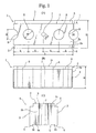
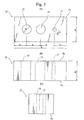
- FIGS. 1 to 4 Various kinds of profiles of bricks are illustrated in plan, front elevational and side elevational views of FIGS. 1 to 4, and the profile of metallic plates inserted between the vertically adjacent bricks are illustrated in a plan view of FIG. 5.
- a profile of a regular brick is illustrated in FIG. 1, and a profile of a flat-bottom-type brick is illustrated in FIG. 2.
- FIGS. 3 and 4 there are shown profiles of irregular or purpose-made bricks used for corner parts, such as an external corner, an internal corner or a columnar configuration.
- the regular brick as shown in FIG. 1 is an integrally formed product made from clay by high temperature baking, which has a body portion 2 and offset portions 3 on both sides thereof.
- the approximate length, width and height are set to be, e.g., 240mm, 85mm and 85mm, respectively.
- the body portion 2 is provided with a flat top face 2a slightly raised from the offset portion 3, and header faces of the body portion 2 slightly protrude from ends of the offset portion 3 in a direction of a center line of wall.
- joint filler such as a sealing compound.
- the raised section and header face section of the body portion 2 function as backing means for the joint filler when the filler is injected into the joints.
- the external surface of the offset portion 3 presents a pattern, color and visual character peculiar to bricks.
- the offset portion 3 is, e.g., 10 mm to 15mm in thickness and the total width T of the brick 1 including the offset portion 3 is set to be approximately 110mm.
- the length and height of the offset portion 3 are set to be slightly smaller than those of the body portion 2. For example, the offset portion 3 is approximately 230mm and 75mm in length and height.
- the lower end portion of the offset portion 3 forms a skirt 4 depending from a lower face of the body portion 2 by a distance of 3 to 5mm.
- a recess 5 is formed between the skirts 4 on both sides, and the lower face of the bottom portion 2 defines a bottom face 5a of the recess 5.
- Side zones of the bottom face 5a are formed with linear grooves 5b.
- the top and bottom faces 2a, 5b of the brick 1 are ground by a grinding tool after molding and baking processes.
- the recess 5 has a function of parting edges for parting the lower surface of the body portion 2 and the skirts 4, the grinding operation of the bottom face can be limited in an area slightly narrower than the width of the recess 5. Therefore, a grinding tool for the grinding process can relatively easily grind the overall lower face of the body portion 2 to level and flatten the entire area, without wear of the tool by contact with the skirt 4.
- the brick 1 is provided with the top face 2a and the bottom face 5b ground in a grinding process, so that precision of the height of the bricks 1 and accuracy of the bricklaying work in a bricklaying process are substantially improved.
- the top face 2a which is elevated from the upper face of the offset portion 3 by 10 to 15mm as set forth above, is formed with square shoulders 6 of dimension of 10 to 15mm on both sides of the body portion 2.
- the shoulders 6 receive the skirts 4 of the upper brick 1 upon bricklaying work, so that a horizontal joint of 5 to 10mm in size is formed between the vertically adjacent bricks 1. Therefore, sharp edges of the top face 2a and the bottom face 5a, which are made by grinding for improving the accuracy, are concealed behind the skirt 4, and the edges are invisible from the outside.
- the overall wall surface of the bricks 1 shows their desired patterns and appearances, and the horizontal joint structure formed by overlapping the skirt 4 and the elevated section acts to effectively prevent leakage of rain water and the like from occurring, which might be, otherwise, caused by its surface tension.
- the body portion 2 is provided with a bolt hole 7 of a relatively small diameter, through-holes 8 of a relatively large diameter, and semicircular grooves 9 vertically extending on the both end faces. Centers of curvatures of the hole 7, through-holes 8 and grooves 9 are positioned on a center line of the body portion 2, spaced an equal distance from each other, and the through-holes 8 are disposed in symmetric position with respect to the bolt hole 7.
- the through-hole 8 allows the mass of the brick 1 to be reduced for making the lightweight brick 1, and increases the whole surface area of the brick 1 for reduction in drying time of the brick during brick manufacturing process (drying step). Further, the brick 1 with the through-hole 8 having a large diameter is applicable to various types of layout of fastening means (bolts and nuts) in corners of walls, ends of wall, and so forth.
- the flat bottom type of brick 1' as shown in Fig.2 is made by grinding the whole bottom face in a grinding step after forming and baking steps, so that it is not provided with the aforementioned skirt. Therefore, the brick 1' has an overall height H' smaller than an overall height H of the regular brick 1 by a height of the skirt 4. Although the brick 1' differs from the regular brick 1 in that it has an entirely flat bottom face 5a, the other structures and specification thereof is substantially the same as those of the regular brick 1.
- first corner brick 10 A configuration of a first form of corner brick 10 (referred to as "first corner brick 10" hereinafter) is generally illustrated in Fig.3.
- the first corner brick 10 is an integrally formed product which is produced by high-temperature baking of clay, similarly to the aforementioned bricks 1,1'.
- the first corner brick 10 differs from the bricks 1,1' in that the provision of semicircular groove is omitted from the end face so as to make the brick 10 to be an entire rectangular profile, and the top and bottom faces of the brick 10 are wholly ground in a grinding step after forming and baking steps.
- the length L, width T and height H' are set to be, e.g., approximately 230mm, 110mm and 85mm, respectively.
- the first corner brick 10 is provided with the bolt hole 17 having a relatively small diameter and the through-hole 18 having a relatively large diameter, similarly to the aforementioned bricks 1, 1', wherein the bolt hole 17 and through-holes 18 are arranged in order in a longitudinal direction of the brick 10.
- the brick 10 differs from the bricks 1, 1' in that the through-hole 18 is positioned at a center of the brick 10.
- the second through-hole 18 is positioned at a center of one half of the brick 10 and the bolt hole 17 is positioned at a center of the other half of the brick 10.
- the diameters d and D of the hole 17, 18 are respectively set to be substantially the same as those of the holes 7, 8 (approximately 8mm and 40mm).
- Metal plates 51, 52 are shown in Fig. 6, which can be inserted between vertically adjacent bricks.
- the two-holes plate 51 is illustrated in Fig. 6(A), the plate having a length approximately equal to the length of brick 1.
- a three-holes plate 52 is shown in Fig.6 (B), the length of plate 52 being one and half times as long as the length of brick 1.
- the plates 51,52 are made to be rectangular thin plates which are approximately 1mm in thickness, and the width of plate 51,52 is set to be slightly smaller than the width of body portion 2.
- the plates 51,52 are provided with bolt holes 53 of a relatively small diameter and a bolt hole 54 of a relatively large diameter. Normally, the holes 53,54 are alternately positioned.
- a diameter of the bolt hole 53 is set to be slightly larger than the external diameter of a brick-fastening bolt (Fig. 6), and a diameter of the bolt hole 54 is set to be larger than the diameter of the bolt hole by approximately 6mm.
- a sufficient clearance is given in the hole 54 so that positioning of the plates 51, 52 relative to the brick 1 can be simplified by approximately situating the hole 54 and that a setting error of the bolt 60 (inclination or horizontal deviation) is allowable, which may be caused during bricklaying work.
- adjuster plates (not shown) having a suitable thickness are used for bricklaying work.
- several types of metal plates or metal strips having thickness of 2mm, 3mm and the like are prepared in advance as being adjuster plates.
- Such adjuster plates are properly inserted between the vertically adjacent bricks when leveling work of the bricks is required.
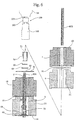
- FIGS.6 through 8 are cross-sectional views and a perspective view showing a standard bricklaying method of the regular brick 1.
- the plates 51 are positioned on the upper surface of the brick 1A:1B which has been already laid in position, and a circular washer 63 and a spring washer 62 are positioned on the plate 51 so as to be in registration with the bolt hole 53.
- a nut 70 is engaged with an upper end portion of the bolt 60A which extends through the hole 53 and washers 63, 62, and protrudes upwardly. The upper end portion of the bolt 60A is tightened to the lower half of an internal thread groove 71.
- the bricks 1C for the upper layer are laid on the brick 1B residing in the lower layer.
- the channel 80 is formed by the semicircular grooves 9 of the adjacent bricks 1C, and the nut 70 is contained in the channel 80.
- the metal plate 51 is laid on the bricks 1C and the bricks 1D for the still upper layer are further laid on the plate 51.
- a bolt 60B is inserted into the bolt hole 7 of the brick 1D so that the lower end portion of the bolt 60B is screwed into the nut 70.
- the aforementioned fixing tool 100 is used for tightening the bolt to the nut 70.
- the socket part 102 of the tool 100 receives the upper end portion of the bolt 60B to transmit the torque of the driving mechanism 101 to the bolt 60B, so that the bolt 60B is rotated in its fixing direction. As the result, the bolt 60B is securely tightened to the nut 70.
- the brick-laid condition of the bricks 1A:1B:1C:1D thus constructed is shown in Fig. 7.
- the steps of assembling the bricks 1, washers 63, 62, bolt 60 and nut 70 are repeatedly carried out in the layers above the bricks 1C:1D, whereby a continuous wall is constructed with the bricks 1 being integrally laid by the constituents or elements 60:62:63:70 of the fastening means.
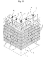
- the walls W of the bricks 1 join together at a right angle to each other in a corner of the building and the like so as to form a corner part C.
- the first corner bricks 10 as shown in Fig. 3 are laid at a right angle to each other in an alternate order.
- the through-hole 18 of the brick 10 positioned at the externally projected corner is vertically aligned with each other to form a continuous vertical hole having a relatively large diameter at the external corner.
- Long and fully screw-threaded bolts 65 are inserted into the hole 18 and connected to each other by long nuts (not shown) in a similar manner as in the aforementioned bolts 60.
- An L-shaped metal plate 55 is positioned in the uppermost layer of the wall W and nuts 69 are screwed on the bolts 65.
- the continuously connected bolts 65 are tightened throughout by a high tightening torque when the uppermost nut 69 is screwed on the bolt 65, and pre-stress is introduced into the bolts 65.
- the corner part C can be constructed with use of the holes 17, 18 of the brick 10.
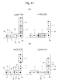
- Figs. 10 and 11(B) are perspective views showing an alternative embodiment of the corner part as shown in Figs. 9 and 11 (A).
- the second corner bricks 20 as shown in Fig. 4 (A) are laid at a projecting corner part.
- the semicircular grooves 29 of the bricks 20 define channels 80 for containing the long nut in cooperation with the semicircular grooves 9 of the adjacent brick 1, every second step. Therefore, the bolt hole 7 for inserting the bolt 60 therethrough and the channel 80 for containing the nut 70 are provided every second step as shown in Fig. 11(B).
- desired pre-stress can be imposed on the bricks 1 adjacent to the second corner bricks 20 by application of the bricklaying structure as shown in Figs. 6 to 8.
- the third and fourth corner bricks 30, 40 as shown in Figs. 4(B) and 4(C) may be laid at the corner part C in an alternate order.
- the architectural wall W is provided with various kinds of openings, e.g., openings for window frames, door frames, building utility system and so forth.
- the fourth corner brick 40 as shown in Fig 4 (C) is used for a frame F of opening in the single-brick wall as shown in Fig. 12.
- regular bricks 1, flat-bottom-type bricks 1' and column bricks 90 are used around the opening of wall.
- the column brick 90 a plan view of which is generally shown in Fig. 12, has overall dimensions corresponding to a half of the corner brick 40, and is provided with a bolt hole 97 positioned at its center and a semicircular groove 99 on its end face. Since the fourth corner brick 40 does not have the skirt 4 and the shoulder 6, the flat-bottom-type bricks 1' are used in the portion partially overlapping the bricks 40.
- bricklaying work starts from the regular bricks 1 to be in the lowermost position of the opening.
- the bricks 40, 90 are alternately laid so as to make the channels 80, every second step, with use of the semicircular grooves 99 of the column bricks 90 and the groove 9 of the flat-bottom-type bricks 1' , and contain the long nuts 70 in the channels 80.
- the bricks 40, 90 of the opening frame portion F is vertically built-up with use of bolts 60, the nut 70 and the plates 51, 52 in relation to the channels 80 and the bolt holes 47.
- the bolts 60 and the nuts 70 are alternately positioned in the holes 97, 48 and securely tightened with each other.
- the pre-stress by the tightening force of the bolts 60 and the nuts 70 is imposed on the bricks 40, 90 upon this process, as described above.
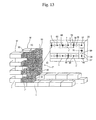
- the third corner bricks 30 are used to construct the opening frame portion F for the double-bricks wall as shown in Fig. 13.
- the bricks 30 are laid in an alternate order with use of the bolts 60, long nuts 70 and plates 51, 52 so that pre-stress by the tightening force of the bolts 60 and the nuts 70 is imposed on the bricks 30.
- the flat-bottom-type bricks 1' are used in the portion partially overlapping the bricks 30 so that the opening frame portion F is formed in continuation with the wall W of the regular bricks 1.
- the wall constructed by the regular bricks 1, especially a single-brick wall supports a horizontal member B such as a beam or girder constituting a floor structure of second floor, a roof truss or the like, it would be necessary to provide a column-configured part E as shown in Fig. 14 in order to support the load of the horizontal member B.
- a horizontal member B such as a beam or girder constituting a floor structure of second floor, a roof truss or the like
- the column-configured part E as shown in Fig. 14 is constructed by laying a pair of first corner bricks 10 in each step and arranging them at a right angle in turn every step.
- the bolt hole 17 and through-hole 18 of the first corner brick 10 are arranged vertically in an alternate order and the metal plates 51 are interposed between the bricks 10 in the respective steps.
- the bricks 10 are laid while tightening the bolts 60 and nuts 70, and this allows the integral column-configured part E to be constructed while pre-stress are imposed on the bricks 10.
- a bolt hole at the end of horizontal member B is engaged to a portion of the bolt 60 protruding from the upper end face of the column-configured part E and a nut 66 is securely tightened to the bolt 60 so as to fix the end portion of the member B on the top end of the column-configured part E.
- the dimensions of the bricks can be appropriately modified in accordance with various kinds of standards, such as a building standard, industrial standard and so forth.
- the present invention can provide a bricklaying structure and a bricklaying method which can be adapted to a variety of building structural details, e.g., corner, opening and columnar configurations.
- the present invention can provide a brick manufacturing method of manufacturing bricks adaptable to a variety of building structural details, e.g., corner, opening and columnar configurations.
Landscapes
- Engineering & Computer Science (AREA)
- Architecture (AREA)
- Physics & Mathematics (AREA)
- Electromagnetism (AREA)
- Civil Engineering (AREA)
- Structural Engineering (AREA)
- Finishing Walls (AREA)
- Road Paving Structures (AREA)
Abstract
Description
said brick provided with a bolt hole (7;17;27;37;47) of a small diameter vertically extending through the brick and at least two through-holes (8;18;28;38;48) having a diameter larger than the diameter of said bolt hole,
wherein said bolt hole has a diameter which allows a bolt (60) constituting said fastening means to extend therethrough,
said through-hole has a diameter for containing a nut (70) which can be engaged with said bolt,
said bolt hole and through-holes are arranged on a longitudinal center line of said brick in order, and a center of said bolt hole, centers of said through-holes and respective end faces of said brick are spaced apart an equal distance from each other in a longitudinal direction of said brick.
stacking corner bricks (10;20;30;40), each having a through-hole (18;28;38;48) vertically extending therethrough with a diameter of said through-hole being larger than a diameter of said bolt hole (17;27;37;47), so that said through-holes are vertically arranged in order; and
inserting through said through-hole, a large diameter long bolt (65) with its diameter being larger than that of said small diameter bolt, and securely tightening said corner bricks by said long bolt.
stacking corner bricks (10;20;30;40), each having a through-hole (18;28;38;48) vertically extending therethrough with a diameter of said through-hole being larger than a diameter of said bolt hole (17;27;37;47), so that said bolt holes and said through-holes are vertically and alternately arranged in order; and containing in said through-hole, nuts (70) engageable with said small diameter bolts to securely tighten said corner bricks with said small diameter bolts and said nuts.
forming a bolt hole (7;17;27;37;47) vertically extending through the brick and at least two through-holes (8;18;28;38;48), with the holes being spaced an equal distance from each other on a longitudinal center line of the brick, said bolt hole having a diameter for allowing a bolt (60) of said fastening means to extend therethrough, and said through-hole having a diameter for containing a nut (70) engageable with said bolt,
whereby plural sorts of irregular bricks applicable to architectural details of structure are manufactured in dependence on arrangements of said bolt hole and through-holes.
Claims (10)
- A bricklaying structure which has bricks and metal plates stacked, and fastening means extending through bolt holes of the bricks, the fastening means securely tightened to integrally connect the vertically adjacent bricks under pre-stress,
wherein said brick is provided with a bolt hole (7;17;27;37;47) of a small diameter vertically extending through the brick and at least two through-holes (8;18;28;38;48) having a diameter larger than the diameter of said bolt hole,said bolt hole has a diameter which allows a bolt (60) constituting said fastening means to extend therethrough,said through-hole has a diameter for containing a nut (70) which can be engaged with said bolt,said bolt hole and through-holes are arranged on a longitudinal center line of said brick in order, and a center of said bolt hole, centers of said through-holes and respective end faces of said brick are spaced apart an equal distance from each other in a longitudinal direction of said brick. - A bricklaying structure as defined in claim 1, wherein said end face of the brick is provided with a vertical groove (9;29;39;49) in a form of semicircle, a center of curvature of the groove is positioned on said center line, and the vertical groove provides a vertical channel (80) in cooperation with a vertical groove of an adjacent brick, the channel having a diameter for containing the nut.
- A bricklaying structure as defined in claim 1 or 2, wherein said through-holes form a vertically continuous hole through which a long bolt (65) of a large diameter can be inserted, when the bricks are laid in a condition that said bricks are alternately oriented at a right angle with each other and that said through-holes are vertically in alignment with each other.
- A bricklaying method in which bricks and metal plates with bolt holes are alternately stacked and small diameter bolts (60) extending through said bolt holes are securely tightened to vertically and integrally connect said bricks with each other, while giving pre-stress to said bolts, comprising the steps of:stacking corner bricks (10;20;30;40), each having a through-hole (18;28;38;48) vertically extending therethrough with a diameter of said through-hole being larger than a diameter of said bolt hole(17;27;37;47) , so that said through-holes are vertically arranged in order; andinserting through said through-hole, a large diameter long bolt (65) with its diameter being larger than that of said small diameter bolt, and securely tightening said corner bricks by said long bolt.
- A bricklaying method as defined in claim 4, wherein a straight wall (W) is constructed by laying regular bricks (1), each having a raised center part (2a) on its top face and a skirt (4) along a side edge of its bottom face, the corner bricks is laid at a corner part (C) of the wall, and flat-bottom-type bricks (1') are laid at a portion of the wall at least partially overlapping the corner bricks, said flat-bottom-type brick having a configuration of said regular brick from which said skirt is excluded.
- A bricklaying method in which bricks and metal plates with bolt holes are alternately stacked and small diameter bolts (60) extending through said bolt holes are securely tightened to vertically and integrally connect said bricks with each other, while imposing pre-stress on said bolts, comprising the steps of:stacking corner bricks (10;20;30;40), each having a through-hole (18;28;38;48) vertically extending therethrough with a diameter of said through-hole being larger than a diameter of said bolt hole (17;27;37;47), so that said bolt holes and said through-holes are vertically arranged in an alternate order; and containing in said through-hole, nuts (70) engageable with said small diameter bolts to securely tighten said corner bricks with said small diameter bolts and said nuts.
- A bricklaying method as defined in claim 6, wherein a straight wall (W) is constructed by laying regular bricks (1), each having a raised center part (2a) on its top face and a skirt (4) along a side edge of its bottom face, the corner bricks are laid at a corner part (C) of the wall, and a flat-bottom-type bricks (1') are laid at a portion of the wall at least partially overlapping the corner bricks, said flat-bottom-type brick having a configuration of said regular brick from which said skirt is excluded.
- A bricklaying method as defined in claim 6, wherein said corner bricks are arranged in parallel in each step, said corner bricks vertically adjacent to each other are oriented at a right angle with each other, and said nuts (70) contained in said through-holes of the corner bricks and the bolts (60) inserted into said bolt holes of the corner bricks are connected with each other so as to make a columnar configuration.
- A method of manufacturing a brick used for a bricklaying structure in which the bricks and metal plates are alternately stacked and fastening means extending through bolt holes of the bricks is securely tightened so as to connect the vertically adjacent bricks integrally under pre-stress of the said fastening means, comprising:whereby plural sorts of irregular bricks applicable to architectural details of structure are manufactured in dependence on arrangements of said bolt hole and through-holes.forming a bolt hole (7;17;27;37;47) vertically extending through the brick and at least two through-holes (8;18;28;38;48) with the holes being spaced an equal distance from each other on a longitudinal center line of the brick, said bolt hole having a diameter for allowing a bolt (60) of said fastening means to extend therethrough, and said through-hole having a diameter for containing a nut (70) engageable with said bolt,
- A method of manufacturing a brick as defined in claim 9, wherein an end face of the brick is provided with a vertical semicircular groove (9;29;39;49), and the groove provides a vertical channel (80) in cooperation with a vertical groove of an adjacent brick, the channel having a diameter for containing the nut (70) of said fastening means.
Applications Claiming Priority (3)
| Application Number | Priority Date | Filing Date | Title |
|---|---|---|---|
| JP2000270219 | 2000-09-06 | ||
| JP2000270219A JP3749825B2 (en) | 2000-09-06 | 2000-09-06 | Brick masonry structure, brick masonry construction method and brick |
| PCT/JP2001/007681 WO2002020913A1 (en) | 2000-09-06 | 2001-09-05 | Brick laying structure, brick laying method, and brick manufacturing method |
Publications (2)
| Publication Number | Publication Date |
|---|---|
| EP1325990A1 true EP1325990A1 (en) | 2003-07-09 |
| EP1325990A4 EP1325990A4 (en) | 2005-10-05 |
Family
ID=18756693
Family Applications (1)
| Application Number | Title | Priority Date | Filing Date |
|---|---|---|---|
| EP01963424A Withdrawn EP1325990A4 (en) | 2000-09-06 | 2001-09-05 | BRICK INSTALLATION STRUCTURE, BRICK INSTALLATION METHOD, AND BRICK MANUFACTURING METHOD |
Country Status (7)
| Country | Link |
|---|---|
| US (1) | US6915614B2 (en) |
| EP (1) | EP1325990A4 (en) |
| JP (1) | JP3749825B2 (en) |
| AU (2) | AU8442601A (en) |
| CA (1) | CA2421932C (en) |
| NZ (1) | NZ524640A (en) |
| WO (1) | WO2002020913A1 (en) |
Cited By (3)
| Publication number | Priority date | Publication date | Assignee | Title |
|---|---|---|---|---|
| WO2004011734A1 (en) | 2002-07-31 | 2004-02-05 | Japan Science And Technology Agency | Method for planning construction of brick wall |
| WO2006075827A1 (en) * | 2004-04-28 | 2006-07-20 | Jong-Sam Heo | A prefab block for use much |
| WO2007051262A1 (en) * | 2005-11-02 | 2007-05-10 | Elchin Nusrat Ogli Khalilov | Antiseismic construction |
Families Citing this family (93)
| Publication number | Priority date | Publication date | Assignee | Title |
|---|---|---|---|---|
| FR2830270B1 (en) * | 2001-09-28 | 2003-11-07 | Louis Roumagere | ASSEMBLY MODULE FOR BUILDING BUILDINGS AND METHOD FOR CONSTRUCTING BUILDINGS FROM THIS MODULE |
| US6948282B2 (en) * | 2003-01-09 | 2005-09-27 | Allan Block Corporation | Interlocking building block |
| KR101131364B1 (en) * | 2003-03-06 | 2012-04-04 | 독립행정법인 과학기술진흥기구 | Wall construction of architectural structure |
| FR2864577B1 (en) * | 2003-12-24 | 2006-05-05 | Saint Gobain Ct Recherches | FILTRATION STRUCTURE, ESPECIALLY PARTICULATE FILTER FOR EXHAUST GASES OF AN INTERNAL COMBUSTION ENGINE AND REINFORCING MEMBER FOR SUCH A STRUCTURE |
| US20050188644A1 (en) * | 2004-02-10 | 2005-09-01 | Moure Manuel E. | Prefabricated Structural Panel of Post-Stressed Wood for the Manufacture of Immovable Properties |
| FR2871487B1 (en) * | 2004-06-15 | 2006-09-08 | Dev Construction Ecologique Sa | METHOD FOR PRODUCING A WALL FROM HEMP AND LIME, BLOCKS FOR ITS USE AND DEVICE FOR MOLDING SAID BLOCKS |
| US20070294978A1 (en) * | 2004-12-09 | 2007-12-27 | Fsn Research, Llc | Web offset lug dry-stack system |
| USD527467S1 (en) * | 2005-01-18 | 2006-08-29 | Kaine Malcolm Andrew Telford | Lightweight building block |
| CA2496066C (en) * | 2005-02-04 | 2012-05-29 | Jean-Robert Tremblay | Method and implements for erecting walls including a plurality of wall components |
| ES2364606T3 (en) | 2005-06-28 | 2011-09-07 | Japan Science And Technology Agency | METHOD FOR CONFORMING A UNIT OF MAMPOSTERY AND SUCH UNIT OF MAMPOSTERY. |
| US7934345B2 (en) * | 2005-11-10 | 2011-05-03 | Marsh Roger F | Systems for building construction by attaching blocks with bolts and vertically spaced flat bars |
| US8893447B1 (en) | 2012-12-05 | 2014-11-25 | J Kevin Harris | Use devices for mechanically secured block assembly systems |
| US9206597B2 (en) * | 2006-02-13 | 2015-12-08 | 3B Construction Solutions, Inc. | Unitized post tension block system for masonry structures |
| CA2537356A1 (en) * | 2006-02-15 | 2007-08-15 | Clifford E. Van Steinburg | Drywall construction method and means therefor |
| US20070234660A1 (en) * | 2006-03-21 | 2007-10-11 | Humphrey Ronald T | Block construction system |
| MX2009004524A (en) | 2006-10-27 | 2009-06-19 | Roger F Marsh | Super unitized post tension block system for high strength masonry structures - with superstrongbloks. |
| US20080118309A1 (en) * | 2006-11-21 | 2008-05-22 | Jan Erik Jansson | Flexible grid and predominantly concrete mat employing same |
| WO2008131288A2 (en) * | 2007-04-19 | 2008-10-30 | Marsh Roger F | Special and improved configurations for unitized post tension block system for masonry structures |
| US9091059B2 (en) * | 2007-09-13 | 2015-07-28 | Robert A. Wrightman | Log building |
| CA2722627A1 (en) * | 2008-05-01 | 2009-11-05 | David C. Paul | Form for a concrete footing |
| US8631616B2 (en) | 2009-01-20 | 2014-01-21 | Skidmore Owings & Merrill Llp | Precast wall panels and method of erecting a high-rise building using the panels |
| US8074414B2 (en) * | 2009-01-20 | 2011-12-13 | Skidmore Owings & Merrill Llp | Precast wall panels and method of erecting a high-rise building using the panels |
| JP5321974B2 (en) * | 2009-08-17 | 2013-10-23 | Sayyas Japan株式会社 | Brick wall seismic structure for brick building |
| JP5321972B2 (en) * | 2009-08-17 | 2013-10-23 | Sayyas Japan株式会社 | Seismic reinforcement method for brick wall of brickwork building |
| US8082710B2 (en) * | 2009-08-21 | 2011-12-27 | Ballistics Technology International Ltd. | Removable attachment system for buildings |
| US8863476B2 (en) * | 2009-12-22 | 2014-10-21 | Gary Summers | Building block system |
| US8225578B2 (en) * | 2010-01-11 | 2012-07-24 | Mohammad Reza Azizi Ronagh | Flexible interlocking mortarless wall unit and construction method |
| US8281528B2 (en) * | 2010-03-30 | 2012-10-09 | Pointblank Design Inc. | Apparatus for securing wall members for log homes |
| KR101078991B1 (en) * | 2010-04-28 | 2011-11-01 | 김유지 | Precast Concrete Structure and Construction Method |
| US8925275B2 (en) * | 2010-05-10 | 2015-01-06 | Flooring Industries Limited, Sarl | Floor panel |
| BE1019331A5 (en) | 2010-05-10 | 2012-06-05 | Flooring Ind Ltd Sarl | FLOOR PANEL AND METHODS FOR MANUFACTURING FLOOR PANELS. |
| BE1019501A5 (en) | 2010-05-10 | 2012-08-07 | Flooring Ind Ltd Sarl | FLOOR PANEL AND METHOD FOR MANUFACTURING FLOOR PANELS. |
| US8266862B2 (en) * | 2010-05-13 | 2012-09-18 | Chien-Hua Huang | Prefabricated wall/floor panel |
| IT1408522B1 (en) * | 2010-10-20 | 2014-06-27 | Martigli | CASSERO TO LOSE ASSEMBLY WITH WHICH MODULAR FORMWORKS FOR BUILDING CONCRETE FOUNDATIONS FORM |
| US8898990B2 (en) * | 2011-05-27 | 2014-12-02 | Coobs Canada Ltd. | Modular building blocks with interlocking reinforcement rods |
| CA2778096A1 (en) * | 2011-05-27 | 2012-11-27 | Coobs Canada Ltd. | Modular building blocks with interlocking reinforcement rods |
| CA2852645C (en) * | 2011-06-06 | 2017-07-18 | Christopher GENEST | Masonry block system |
| EP2758611A2 (en) * | 2011-08-09 | 2014-07-30 | Tie-Cast Systems, Inc. | Masonry reinforcement system |
| US8720130B2 (en) * | 2011-08-19 | 2014-05-13 | Mark R. Weber | Leveling block for a wall construction system |
| CN103192452B (en) * | 2012-01-04 | 2015-09-02 | 赵正义 | The termination protective construction of unbounded post-tensioned prestressed concrete structure |
| US9315992B2 (en) * | 2012-02-18 | 2016-04-19 | Geovent LLC | Convex structural block for constructing parabolic walls |
| KR101412414B1 (en) * | 2012-05-21 | 2014-06-27 | 서울시립대학교 산학협력단 | Brick constructing method using reinforcing member |
| JP5201286B1 (en) * | 2012-08-21 | 2013-06-05 | 浩二 渡邊 | Structure constituting unit, structure constituted by structure constituting unit, and method for constructing structure by structure constituting unit |
| ITTO20121042A1 (en) * | 2012-12-04 | 2014-06-05 | Flavio Lanese | REUSABLE MODULE FOR THE REALIZATION OF AT LEAST A PORTION OF A REMOVABLE WALL OF A CONSTRUCTION |
| JP5447896B1 (en) * | 2013-01-01 | 2014-03-19 | 義孝 矢島 | Building and building block products and masonry methods |
| US20150013255A1 (en) * | 2013-03-14 | 2015-01-15 | Christopher M. Hunt | Hybrid cementitious buildings for a multi-level habitat |
| AU2015209142B2 (en) * | 2014-01-23 | 2018-08-30 | Harvel K. Crumley | System and method for retrofitting walls with retaining ties |
| US10364569B2 (en) * | 2014-01-23 | 2019-07-30 | Harvel K. Crumley | Guide device for retaining ties in masonry walls |
| US9021762B1 (en) * | 2014-02-06 | 2015-05-05 | Frank DePalma | Interlocking concrete blocks with trapezoidal shape |
| US10113305B2 (en) * | 2014-08-01 | 2018-10-30 | Just Biofiber Structural Solutions Corp. | Load bearing interlocking structural blocks and tensioning system |
| US9523201B2 (en) * | 2014-09-12 | 2016-12-20 | Sergei V. Romanenko | Construction components having embedded internal support structures to provide enhanced structural reinforcement for, and improved ease in construction of, walls comprising same |
| US9194125B1 (en) * | 2014-09-12 | 2015-11-24 | Sergei V. Romanenko | Construction component having embedded internal support structures to provide enhanced structural reinforcement and improved ease of construction therewith |
| US9677267B2 (en) | 2014-10-15 | 2017-06-13 | Block Florida, LLC | Construction blocks and systems |
| US9074362B1 (en) * | 2014-10-15 | 2015-07-07 | Block Florida, LLC | Construction blocks and systems |
| US9133619B1 (en) * | 2014-11-20 | 2015-09-15 | Spherical Block LLC | Architectural building block |
| CN105986634A (en) * | 2015-02-11 | 2016-10-05 | 镇江市龙门石刻艺术工程有限公司 | Prestressed stone plate and beam and prestressed stone component using same |
| GB2537804B (en) | 2015-02-20 | 2020-07-15 | Atkinson Stephen | Improvements in or relating to bricklaying |
| KR101518359B1 (en) * | 2015-03-27 | 2015-05-07 | 주식회사 천일건축엔지니어링 종합건축사사무소 | Masonry Brick Walls Coupling Apparatus for Apartment House |
| JP6499526B2 (en) * | 2015-06-16 | 2019-04-10 | 旭化成ホームズ株式会社 | Masonry unit and method |
| JP6573490B2 (en) * | 2015-06-16 | 2019-09-11 | 旭化成ホームズ株式会社 | building |
| US10358819B2 (en) | 2015-07-16 | 2019-07-23 | Yonathan TANAMI | Construction block, a wall structure comprising the same, and a method for manufacture of said construction block and of said wall structure |
| US9938763B2 (en) | 2015-11-05 | 2018-04-10 | Tim Miller | System and method for a security film |
| KR102058423B1 (en) * | 2016-07-22 | 2019-12-23 | 주식회사 대도벽돌시스템 | Direct vision type brick wall and construction method thereof |
| IT201600124054A1 (en) * | 2016-12-06 | 2018-06-06 | Marco Citro | MODULE FOR CONSTRUCTION OF BUILDING STRUCTURES |
| AU2018333845B2 (en) * | 2017-09-14 | 2022-12-08 | Jenner Innovation Pty Ltd | System for building a load bearing structure |
| CN109900121A (en) * | 2017-12-07 | 2019-06-18 | 中国二十冶集团有限公司 | Annealing furnace light-weight brick furnace wall jumps storehouse masonry method |
| US10781588B1 (en) * | 2018-01-25 | 2020-09-22 | Marc R Nadeau | Integrated, post-tensioned, building construction system |
| BR102018003399B1 (en) * | 2018-02-21 | 2019-11-05 | Marcelo Schuetz Jardim | prefabricated brick building and assembly process of this building |
| CN112888651B (en) | 2018-07-19 | 2024-08-16 | 能源库公司 | Energy storage system and method |
| CN108756018B (en) * | 2018-08-30 | 2023-10-27 | 刘晓峰 | Building brick connecting device and building brick curtain wall |
| CN108797841A (en) * | 2018-09-10 | 2018-11-13 | 周雄浩 | A kind of fast disassembly type light weight hollow is laid bricks and fast disassembly type wall body structure |
| US10934705B2 (en) | 2018-11-20 | 2021-03-02 | Max-Block Development L.L.C. | Wall construction members and system |
| JP6616031B1 (en) * | 2019-02-27 | 2019-12-04 | 高原木材株式会社 | Block member set |
| CN110644671A (en) * | 2019-10-11 | 2020-01-03 | 龙川县兴镔环保科技有限公司 | Load-bearing concrete porous brick |
| KR102108786B1 (en) * | 2019-11-12 | 2020-05-11 | 강준호 | Fixture of heat insulating material for masonry wall |
| CN110922071B (en) * | 2019-12-16 | 2024-06-11 | 中冶长天国际工程有限责任公司 | Bricklaying and construction method for annular channel of double-chamber lime kiln |
| KR102142230B1 (en) * | 2019-12-31 | 2020-08-07 | 청화요업(주) | Brick masonry system for seismic design |
| KR102200978B1 (en) * | 2019-12-31 | 2021-01-12 | 청화요업(주) | Dry Masonry Bricks and Seismic Dry Masonry Structures Using the Same |
| MX2022008165A (en) | 2020-01-22 | 2022-08-19 | Energy Vault Inc | Grabber comprising a damped self-centering mechanism. |
| AU2021237982B2 (en) * | 2020-03-16 | 2023-02-09 | MTD Holdings NSW Pty Ltd | Prefabricated wall assembly and method therefor |
| CN114746356A (en) | 2020-06-30 | 2022-07-12 | 能源库公司 | Energy storage and delivery system and method |
| CN112095845B (en) * | 2020-09-14 | 2021-10-22 | 中国水电基础局有限公司 | House building wall structure and construction method |
| CN112554377B (en) * | 2020-11-27 | 2022-02-08 | 启迪设计集团股份有限公司 | Perforated brick hollow brick wall and construction process thereof |
| US12132312B2 (en) * | 2020-12-24 | 2024-10-29 | Energy Vault, Inc. | Energy storage system with elevator lift system |
| US11525437B2 (en) | 2021-02-02 | 2022-12-13 | Energy Vault, Inc. | Energy storage system with elevator lift system |
| US20250012037A1 (en) * | 2021-03-17 | 2025-01-09 | Robert Gordon McIntosh | Retaining wall systems |
| US20250067014A1 (en) * | 2021-03-17 | 2025-02-27 | Robert Gordon McIntosh | Retaining wall systems |
| US12215676B2 (en) | 2021-07-07 | 2025-02-04 | Energy Vault, Inc. | Lift drive system for energy storage and delivery system |
| CN113916004A (en) * | 2021-11-10 | 2022-01-11 | 安徽瑞泰新材料科技有限公司 | An integrated kiln body refractory brick connection structure |
| CN116262588A (en) | 2021-12-13 | 2023-06-16 | 能源库公司 | Energy storage and delivery systems and methods |
| KR102683707B1 (en) * | 2022-05-18 | 2024-07-11 | 이원경 | Structure for assembly furniture |
| US11982261B1 (en) | 2023-04-10 | 2024-05-14 | Energy Vault, Inc. | Energy storage and delivery system and method |
| CN117248658A (en) * | 2023-11-06 | 2023-12-19 | 中铁十局集团城建工程有限公司 | A kind of glazed landscape wall installation and fixing device and installation method |
Family Cites Families (13)
| Publication number | Priority date | Publication date | Assignee | Title |
|---|---|---|---|---|
| US2241169A (en) * | 1937-12-08 | 1941-05-06 | Yokes Otto | Building construction |
| JPS57205658A (en) * | 1981-06-09 | 1982-12-16 | Kobayashi Bolt Kogyo | Integral execution method for block wall surface |
| US4823528A (en) * | 1987-02-03 | 1989-04-25 | Garland Faw | Log wall and corner joint for log building structures |
| JPH0696920B2 (en) * | 1988-08-23 | 1994-11-30 | 重一 鈴木 | Assembly connection wall |
| FR2652845B1 (en) * | 1989-10-05 | 1993-04-23 | Ivaldi Marc | CONSTRUCTION ASSEMBLY. |
| JPH05255982A (en) | 1992-03-10 | 1993-10-05 | Taisuke Matsufuji | Stack structure of stacked block group |
| JP3319808B2 (en) | 1993-04-19 | 2002-09-03 | 泰典 松藤 | Block masonry structure |
| JPH07229215A (en) | 1994-02-17 | 1995-08-29 | 利貞 ▲廣▼岡 | Brick block unit and manufacturing therefor |
| JPH0921199A (en) | 1995-07-07 | 1997-01-21 | Taisuke Matsufuji | Block laying structure |
| JPH09235801A (en) * | 1996-02-29 | 1997-09-09 | Taisuke Matsufuji | Beam erect construction method of block laying structure |
| US6557316B2 (en) * | 1997-04-21 | 2003-05-06 | Franciscus Antonius Maria Van Der Heijden | Building system comprising individual building elements |
| NL1005850C2 (en) * | 1997-04-21 | 1998-10-27 | Franciscus Antonius Maria Van | Building system comprising separate building elements. |
| DE29800706U1 (en) * | 1998-01-16 | 1999-02-11 | KS-Quadro Verwaltungsgesellschaft mbH, 23992 Neukloster | Kit for creating masonry |
-
2000
- 2000-09-06 JP JP2000270219A patent/JP3749825B2/en not_active Expired - Fee Related
-
2001
- 2001-09-05 CA CA 2421932 patent/CA2421932C/en not_active Expired - Fee Related
- 2001-09-05 US US10/363,128 patent/US6915614B2/en not_active Expired - Fee Related
- 2001-09-05 EP EP01963424A patent/EP1325990A4/en not_active Withdrawn
- 2001-09-05 NZ NZ524640A patent/NZ524640A/en not_active IP Right Cessation
- 2001-09-05 WO PCT/JP2001/007681 patent/WO2002020913A1/en not_active Ceased
- 2001-09-05 AU AU8442601A patent/AU8442601A/en active Pending
- 2001-09-05 AU AU2001284426A patent/AU2001284426B2/en not_active Ceased
Cited By (5)
| Publication number | Priority date | Publication date | Assignee | Title |
|---|---|---|---|---|
| WO2004011734A1 (en) | 2002-07-31 | 2004-02-05 | Japan Science And Technology Agency | Method for planning construction of brick wall |
| EP1548199A4 (en) * | 2002-07-31 | 2007-05-02 | Japan Science & Tech Agency | METHOD FOR PLANNING THE CONSTRUCTION OF A BRICK WALL |
| CN1329596C (en) * | 2002-07-31 | 2007-08-01 | 独立行政法人科学技术振兴机构 | Method for planning construction of brick wall |
| WO2006075827A1 (en) * | 2004-04-28 | 2006-07-20 | Jong-Sam Heo | A prefab block for use much |
| WO2007051262A1 (en) * | 2005-11-02 | 2007-05-10 | Elchin Nusrat Ogli Khalilov | Antiseismic construction |
Also Published As
| Publication number | Publication date |
|---|---|
| JP2002081152A (en) | 2002-03-22 |
| JP3749825B2 (en) | 2006-03-01 |
| US20040020145A1 (en) | 2004-02-05 |
| AU2001284426B2 (en) | 2006-08-24 |
| NZ524640A (en) | 2006-04-28 |
| US6915614B2 (en) | 2005-07-12 |
| EP1325990A4 (en) | 2005-10-05 |
| CA2421932A1 (en) | 2003-03-03 |
| CA2421932C (en) | 2008-08-05 |
| AU8442601A (en) | 2002-03-22 |
| WO2002020913A1 (en) | 2002-03-14 |
Similar Documents
| Publication | Publication Date | Title |
|---|---|---|
| CA2421932C (en) | Brick laying structure, brick laying method, and brick manufacturing method | |
| US8171693B2 (en) | Interlocking masonry blocks | |
| US5787666A (en) | Thin masonry veneer panel system and the fabrication thereof | |
| US4823528A (en) | Log wall and corner joint for log building structures | |
| CA1289718C (en) | Glass block panel construction and device for use in same | |
| US4573301A (en) | Interlocking building blocks | |
| US20100192495A1 (en) | Thin stone or brick veneer wall system and clips therefor | |
| CA2613621C (en) | Method for forming masonry unit | |
| US20050257480A1 (en) | Construction block system | |
| CA2511630C (en) | Masonry wall system | |
| US4887403A (en) | Internally indexed building block and method of construction | |
| GB2091777A (en) | Mortarless wall comprising tensioned rods passing through openings in masonry blocks | |
| US4771584A (en) | Concrete block wall construction method | |
| US10202755B2 (en) | Construction block anchoring system | |
| US3292329A (en) | Building construction | |
| GB2394730A (en) | Mortarless brick and locking bolt building system | |
| US6912819B2 (en) | Fastening element for masonry units | |
| AU668058B2 (en) | Building blocks and method of building construction | |
| RU2762271C1 (en) | Construction flooring system | |
| KR20010027276A (en) | Brick with slot and lay bricks method utilizing the same | |
| CN221609176U (en) | Hollow shale brick facing non-bearing enclosure wall | |
| KR200256938Y1 (en) | An edifice structure body by using yellow soil board | |
| JPH0137045Y2 (en) | ||
| JP3020472B2 (en) | Floor structure | |
| JPH0124251Y2 (en) |
Legal Events
| Date | Code | Title | Description |
|---|---|---|---|
| PUAI | Public reference made under article 153(3) epc to a published international application that has entered the european phase |
Free format text: ORIGINAL CODE: 0009012 |
|
| 17P | Request for examination filed |
Effective date: 20030404 |
|
| AK | Designated contracting states |
Designated state(s): AT BE CH CY DE DK ES FI FR GB GR IE IT LI LU MC NL PT SE TR |
|
| AX | Request for extension of the european patent |
Extension state: AL LT LV MK RO SI |
|
| RBV | Designated contracting states (corrected) |
Designated state(s): DE GB GR IT |
|
| RAP1 | Party data changed (applicant data changed or rights of an application transferred) |
Owner name: JAPAN SCIENCE AND TECHNOLOGY AGENCY |
|
| A4 | Supplementary search report drawn up and despatched |
Effective date: 20050819 |
|
| RIC1 | Information provided on ipc code assigned before grant |
Ipc: 7E 04B 2/42 B Ipc: 7E 04B 2/44 A |
|
| GRAP | Despatch of communication of intention to grant a patent |
Free format text: ORIGINAL CODE: EPIDOSNIGR1 |
|
| RTI1 | Title (correction) |
Free format text: BRICKLAYING STRUCTURE AND BRICK LAYING METHOD USING METAL PLATES AND BOLTS |
|
| STAA | Information on the status of an ep patent application or granted ep patent |
Free format text: STATUS: THE APPLICATION IS DEEMED TO BE WITHDRAWN |
|
| 18D | Application deemed to be withdrawn |
Effective date: 20110729 |