EP1323579A2 - Verfahren zur Überprüfung einer automatischen Ansteuerung einer Beleuchtungseinrichtung eines Fahrzeuges und Prüfeinrichtung - Google Patents
Verfahren zur Überprüfung einer automatischen Ansteuerung einer Beleuchtungseinrichtung eines Fahrzeuges und Prüfeinrichtung Download PDFInfo
- Publication number
- EP1323579A2 EP1323579A2 EP02027112A EP02027112A EP1323579A2 EP 1323579 A2 EP1323579 A2 EP 1323579A2 EP 02027112 A EP02027112 A EP 02027112A EP 02027112 A EP02027112 A EP 02027112A EP 1323579 A2 EP1323579 A2 EP 1323579A2
- Authority
- EP
- European Patent Office
- Prior art keywords
- sensor
- lighting device
- signal
- threshold
- light sensor
- Prior art date
- Legal status (The legal status is an assumption and is not a legal conclusion. Google has not performed a legal analysis and makes no representation as to the accuracy of the status listed.)
- Withdrawn
Links
- 238000012360 testing method Methods 0.000 title claims abstract description 44
- 238000000034 method Methods 0.000 title claims abstract description 13
- 230000007257 malfunction Effects 0.000 claims description 22
- 238000011156 evaluation Methods 0.000 description 18
- 238000001514 detection method Methods 0.000 description 4
- 230000002950 deficient Effects 0.000 description 2
- 238000010586 diagram Methods 0.000 description 2
- 238000006073 displacement reaction Methods 0.000 description 2
- 230000001419 dependent effect Effects 0.000 description 1
- 230000023077 detection of light stimulus Effects 0.000 description 1
- 238000005286 illumination Methods 0.000 description 1
- 230000000977 initiatory effect Effects 0.000 description 1
Images


Classifications
-
- B—PERFORMING OPERATIONS; TRANSPORTING
- B60—VEHICLES IN GENERAL
- B60Q—ARRANGEMENT OF SIGNALLING OR LIGHTING DEVICES, THE MOUNTING OR SUPPORTING THEREOF OR CIRCUITS THEREFOR, FOR VEHICLES IN GENERAL
- B60Q1/00—Arrangement of optical signalling or lighting devices, the mounting or supporting thereof or circuits therefor
- B60Q1/02—Arrangement of optical signalling or lighting devices, the mounting or supporting thereof or circuits therefor the devices being primarily intended to illuminate the way ahead or to illuminate other areas of way or environments
- B60Q1/04—Arrangement of optical signalling or lighting devices, the mounting or supporting thereof or circuits therefor the devices being primarily intended to illuminate the way ahead or to illuminate other areas of way or environments the devices being headlights
- B60Q1/14—Arrangement of optical signalling or lighting devices, the mounting or supporting thereof or circuits therefor the devices being primarily intended to illuminate the way ahead or to illuminate other areas of way or environments the devices being headlights having dimming means
- B60Q1/1415—Dimming circuits
- B60Q1/1423—Automatic dimming circuits, i.e. switching between high beam and low beam due to change of ambient light or light level in road traffic
-
- B—PERFORMING OPERATIONS; TRANSPORTING
- B60—VEHICLES IN GENERAL
- B60Q—ARRANGEMENT OF SIGNALLING OR LIGHTING DEVICES, THE MOUNTING OR SUPPORTING THEREOF OR CIRCUITS THEREFOR, FOR VEHICLES IN GENERAL
- B60Q2300/00—Indexing codes for automatically adjustable headlamps or automatically dimmable headlamps
- B60Q2300/10—Indexing codes relating to particular vehicle conditions
- B60Q2300/11—Linear movements of the vehicle
- B60Q2300/112—Vehicle speed
-
- B—PERFORMING OPERATIONS; TRANSPORTING
- B60—VEHICLES IN GENERAL
- B60Q—ARRANGEMENT OF SIGNALLING OR LIGHTING DEVICES, THE MOUNTING OR SUPPORTING THEREOF OR CIRCUITS THEREFOR, FOR VEHICLES IN GENERAL
- B60Q2300/00—Indexing codes for automatically adjustable headlamps or automatically dimmable headlamps
- B60Q2300/10—Indexing codes relating to particular vehicle conditions
- B60Q2300/11—Linear movements of the vehicle
- B60Q2300/116—Vehicle at a stop
-
- B—PERFORMING OPERATIONS; TRANSPORTING
- B60—VEHICLES IN GENERAL
- B60Q—ARRANGEMENT OF SIGNALLING OR LIGHTING DEVICES, THE MOUNTING OR SUPPORTING THEREOF OR CIRCUITS THEREFOR, FOR VEHICLES IN GENERAL
- B60Q2300/00—Indexing codes for automatically adjustable headlamps or automatically dimmable headlamps
- B60Q2300/10—Indexing codes relating to particular vehicle conditions
- B60Q2300/14—Other vehicle conditions
- B60Q2300/146—Abnormalities, e.g. fail-safe
-
- B—PERFORMING OPERATIONS; TRANSPORTING
- B60—VEHICLES IN GENERAL
- B60Q—ARRANGEMENT OF SIGNALLING OR LIGHTING DEVICES, THE MOUNTING OR SUPPORTING THEREOF OR CIRCUITS THEREFOR, FOR VEHICLES IN GENERAL
- B60Q2300/00—Indexing codes for automatically adjustable headlamps or automatically dimmable headlamps
- B60Q2300/30—Indexing codes relating to the vehicle environment
- B60Q2300/31—Atmospheric conditions
- B60Q2300/314—Ambient light
-
- B—PERFORMING OPERATIONS; TRANSPORTING
- B60—VEHICLES IN GENERAL
- B60Q—ARRANGEMENT OF SIGNALLING OR LIGHTING DEVICES, THE MOUNTING OR SUPPORTING THEREOF OR CIRCUITS THEREFOR, FOR VEHICLES IN GENERAL
- B60Q2300/00—Indexing codes for automatically adjustable headlamps or automatically dimmable headlamps
- B60Q2300/30—Indexing codes relating to the vehicle environment
- B60Q2300/33—Driving situation
- B60Q2300/337—Tunnels or bridges
Definitions
- the invention relates to a method for checking an automatic control a lighting device of a vehicle according to the preamble of Claim 1 and a test device according to the preamble of claim 6.
- a device for the automatic switching of lighting devices at Vehicles with a sensor device are known from DE 195 23 262 A1.
- a sensor device is provided which has a global sensor for the Detection of the general lighting conditions in the vicinity of the vehicle and a direction sensor for the directional detection of light conditions in the direction of travel in front of the vehicle. The signals from the sensor device become determines whether a change in the switching state is required.
- Another driving situation-dependent light control with an ambient light sensor and a direction-specific light sensor is known from DE 196 30 216 A1 known.
- EP 1 134 119 A2 A generic method and a generic test facility for Checking an evaluation circuit of an automatic circuit for lighting devices in vehicles are described in EP 1 134 119 A2.
- the EP 1 134 119 A2 relates to DE 195 23 262 A1, from which the intended Sensor device with a global sensor and a direction sensor, the evaluation circuit and how it works, as mentioned.
- the functionality of the evaluation circuit will be checked for plausibility Output signal used. To do this, for example, when switched on the voltage supply to the sensor device is briefly interrupted and checked, whether the output signal corresponds to the simulated "night" state. If so is not the case, i.e. if the evaluation circuit does not function correctly, generates a signal that indicates the malfunction and the initiation further steps are initiated.
- One of these steps can be a control of the Be lighting device that automatically turns on the low beam leads.
- Another step can provide the driver with information about the malfunction the evaluation circuit.
- the object of the invention is a method for checking an automatic Control of a lighting device of a vehicle according to the preamble of claim 1 and a corresponding test device according to the Develop the preamble of claim 6, wherein a check of the signals of the Light sensors enable and thus the safety of the automatic control is increased.
- the signals from at least two are checked Light sensors tested depending on each other.
- the signals from two light sensors have some dependency on each other.
- Signals one Ambient light sensor (global sensor) and an apron sensor (direction sensor) have different brightness values at a certain point in time.
- Their chronological course is, e.g. shown in DE 195 23 262 A1, but except for a time shift similar. This applies e.g. for entry into or one Exit from a tunnel.
- Deviating courses of the signals can indicate a Indicate malfunction of one of the light sensors.
- a device for automatically switching on and off the Illumination of a vehicle with three light sensors is e.g. from DE 199 57 210 A1 known.
- a malfunction of the signal from a first light sensor is detected when the first Condition the signal of the first light sensor above a higher brightness threshold and the signal from a second light sensor below a lower brightness threshold and the second condition is a minimum duration of the first condition is exceeded.
- This check is based on that with two light sensors the signal of a first light sensor on a moving vehicle should display low brightness value if this is a second light sensor already for a minimum period, i.e. for a certain time or after Traveled a certain distance. If not, it is if the signal from the first light sensor is continuously significantly higher, then the first light sensor to be defective. If the light sensor is defective, a signal is sent that corresponds to the highest brightness.
- the exceeding of a minimum duration of the deviation of the signals of the two light sensors can be determined over a predetermined minimum time T or a predetermined minimum distance X, which the vehicle has traveled and which can be calculated or measured by a displacement sensor. If a malfunction is detected, the lighting device is activated.
- the check can be carried out directly from the light sensors Signals or on the basis of signals already smoothed in an evaluation device respectively. In the case of smoothed signals, the detection of a malfunction can also occur indicate a malfunction of the evaluation device.
- one of the two light sensors is preferably an ambient light sensor and the other light sensor is an apron sensor.
- the ambient light sensor fails, i.e. a signal from the ambient light sensor above the switch-off threshold SW II and with a signal from the apron sensor below the switch-on threshold SW I for a minimum period Lighting device switched on.
- the minimum duration is chosen so that e.g. no malfunction is detected when approaching a tunnel.
- the apron sensor fails, i.e. a signal from the apron sensor above the Switch-off threshold SW II, and with a signal from the ambient light sensor below the switch-on threshold SW I over a minimum time T or over a minimum distance X the lighting device is switched on.
- the minimum duration i.e. the minimum time T or the minimum distance X are chosen so that when leaving from a tunnel or a passage under an underpass Malfunction is detected.
- a malfunction of the apron sensor is also detected when the ambient light sensor constantly through roof superstructures, e.g. through a ski case or a surfboard, shadowed and his signal is below the switch-on threshold SW I and that Signal from the apron sensor for a minimum period above the switch-off threshold SW II is e.g. during a day trip.
- This constellation also leads to switch on the lighting device.
- the first condition can be selected. So that can Parking and exit situations in which the first minimum duration, minimum time T or minimum distance X is exceeded. In parking situations the apron sensor could be through a dark house wall or garage entrance be shadowed and its signal in relation to that of the ambient light sensor be too low.
- An error message when a malfunction of the apron sensor is detected should not because, as described, there is a possibility that due to a The ambient light sensor is shaded by roof superstructures.
- test device for checking an automatic Control of a lighting device of a vehicle according to claim 6 is to carry out a method according to claim 1, and testing facilities according to claims 7 to 10 are to carry out methods according to Claims 2 to 5 particularly well suited.
- the test device according to the invention can be integrated into the control device his.
- the control device can be designed as a microcontroller, the one Microprocessor and other components, e.g. comprise an analog / digital converter can.
- the invention is based on exemplary embodiments shown schematically in the drawing further explained.
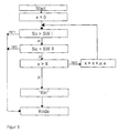
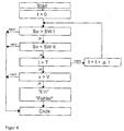
- FIGS. 3 to 5 are flow diagrams Method according to the invention for detecting a malfunction of an apron sensor ( Figure 3) and an ambient light sensor ( Figures 4 and 5).
- a test device is used to test a control device for the automatic control of a lighting device of a vehicle used.
- the control device comprises a sensor device with two light sensors, and with an ambient light sensor 1 and an apron sensor 2, and one Evaluation device 3.
- the ambient light sensor 1 and the apron sensor 2 are connected to the evaluation device 3 for transferring their sensor signals Su and Sv and this for transferring a switching signal to the lighting device 4 ( Figure 2).
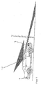
- the two light sensors are designed as photocells and e.g. on top of one Windshield attached ( Figure 1).
- the lighting device 4 can Devices on the vehicle, such as the low beam, and interior lighting include.
- the test device of a first example is part of the evaluation device 3 formed, the ambient light sensor 1 and the apron sensor 2 for transfer their signals Su and Sv and a vehicle speed sensor 5 for transfer a speed signal v are connected to the test device and the test device for transferring a switching signal to the lighting device 4 and connected to a diagnostic device 6 for transferring an error message is.
- the evaluation device 3 can be designed as a microcontroller.
- the test device of the first example has a comparison unit in which a Switch-on threshold SW I and a switch-off threshold SW II are stored, one Delay unit in which a minimum distance X is stored and a second one Comparison unit in which a minimum speed V is stored.
- test device In a second example of the test device is in the delay unit Determination of the minimum duration instead of the minimum distance X stores a minimum time T.
- test device is instead of the second comparison unit a second delay unit with a minimum distance T2 or with a minimum distance X2 provided
- the sensor signals Su and Sv des Ambient light sensor 1 and the apron sensor 2 evaluated and the Lighting device 4 controlled.
- the lighting device 4 is depending on Result of the evaluation of the sensor signals Su and Sv switched on or off or left unchanged.
- test device is used to check the control Evaluation device 3, the two sensor signals Su and Sv depending on each other checked for plausibility and the lighting device upon detection of a malfunction 4 controlled.
- the plausibility checks are carried out in the company, e.g. constantly restarted with the engine running.
- a distance counter is set to x equal to 0.
- the first condition is checked whether the signal Sv of the apron sensor 2 is above the switch-off threshold SW II and the signal Su from the ambient light sensor 1 are below the switch-on threshold SW I. If so, is in the delay unit the test facility checks as a second condition whether the distance covered x is greater than the minimum distance X. If no, the value of the distance covered Path x increased by an amount ⁇ x corresponding to the test interval and the Check carried out again.
- the Distance traveled x can be determined from the measured speed v and the time t calculated or transmitted by a displacement sensor.
- a test device of the second example as a second condition it is checked whether the elapsed time t is greater than a minimum time T.
- the Check a time counter set to t equal to 0.
- the first condition is checked whether the signal Su from the ambient light sensor 1 above the switch-off threshold SW II and the signal Sv of the apron sensor are below the switch-on threshold SW I. If so, is in the delay unit the test facility as a second condition checked whether the elapsed Time t is greater than the minimum time T. If no, the value of the elapsed time becomes t increased by an amount ⁇ t corresponding to the test interval and the test performed again.
- the second comparison unit of the examination unit As a third condition, it is checked whether the vehicle speed sensor 5 measured speed v is greater than the minimum speed V. Falls no, all conditions are checked again. If so, one will Malfunction of the ambient light sensor 1 detected and the lighting device 4 controlled and switched on by a switching signal "on". In addition, an error message is output to the diagnostic unit 6.
- the examination unit in this example are the first comparison unit, the delay unit and the second comparison unit connected in series in this order.
- the third condition is first namely exceeding a minimum speed V, and then checked the second condition.
- the second is in the test facility Comparison unit connected before the delay unit.
- the minimum duration can be a minimum time T2 which is longer than the minimum time T or a minimum distance X2, which is longer than the minimum distance X, are used.
Landscapes
- Engineering & Computer Science (AREA)
- Mechanical Engineering (AREA)
- Lighting Device Outwards From Vehicle And Optical Signal (AREA)
Abstract
Description
Bei Erkennen einer Fehlfunktion wird die Beleuchtungseinrichtung angesteuert.
- 1
- Umgebungslichtsensor
- 2
- Vorfeldsensor
- 3
- Auswerteeinrichtung
- 4
- Beleuchtungseinrichtung
- 5
- Fahrgeschwindigkeitssensor
- 6
- Diagnosegerät
Claims (10)
- Verfahren zur Überprüfung einer automatischen Ansteuerung einer Beleuchtungseinrichtung eines Fahrzeuges, wobei bei der Ansteuerung Signale von Lichtsensoren ausgewertet und die Beleuchtungseinrichtung angesteuert werden, und wobei bei der Überprüfung bei Erkennen einer Fehlfunktion ebenfalls die Beleuchtungseinrichtung angesteuert wird,
dadurch gekennzeichnet, dass
die Signale von mindestens zwei Lichtsensoren in Abhängigkeit voneinander geprüft werden und
eine Fehlfunktion des Signals eines ersten Lichtsensors erkannt wird,
wenn als erste Bedingung das Signal des ersten Lichtsensors oberhalb einer höheren Helligkeitsschwelle und das Signal eines zweiten Lichtsensors unterhalb einer tieferen Helligkeitsschwelle liegen und
als zweite Bedingung eine Mindestdauer der ersten Bedingung überschritten wird. - Verfahren nach Anspruch 1, dadurch gekennzeichnet, dass
als höhere Helligkeitsschwelle eine Ausschaltschwelle SW II und als tiefere Helligkeitsschwelle eine Einschaltschwelle SW I eingesetzt werden. - Verfahren nach Anspruch 1 oder Anspruch 2, dadurch gekennzeichnet, dass die Signale eines Umgebungslichtsensors (1) und eines Vorfeldsensors (2) in Abhängigkeit voneinander geprüft werden.
- Verfahren nach Anspruch 3 und nach Anspruch 2, dadurch gekennzeichnet, dass eine Fehlfunktion des Umgebungslichtsensors (1) erkannt wird, wenn als zusätzliche Bedingung eine Mindestgeschwindigkeit V oder eine zweite, längere Mindestdauer der ersten Bedingung überschritten wird.
- Verfahren nach Anspruch 4, dadurch gekennzeichnet, dass bei Erkennen einer Fehlfunktion des Umgebungslichtsensors (1) eine Fehlermeldung an ein Diagnosegerät (6) ausgegeben wird.
- Prüfeinrichtung zur Überprüfung einer Ansteuereinrichtung zur automatischen Ansteuerung einer Beleuchtungseinrichtung eines Fahrzeuges, wobei an die Ansteuereinrichtung Lichtsensoren angeschlossen sind und die Ansteuereinrichtung an die Beleuchtungseinrichtung angeschlossen ist, und wobei die Prüfeinrichtung ebenfalls an die Beleuchtungseinrichtung angeschlossen ist,
dadurch gekennzeichnet, dass
die Lichtsensoren zusätzlich an die Prüfeinrichtung angeschlossen sind und
die Prüfeinrichtung eine Vergleichseinheit mit einer höheren Helligkeitsschwelle und mit einer niedrigeren Helligkeitsschwelle und eine Verzögerungseinheit aufweist. - Prüfeinrichtung nach Anspruch 6, gekennzeichnet durch eine Vergleichseinheit mit einer Einschaltschwelle SW I und einer Ausschaltschwelle SW II.
- Prüfeinrichtung nach Anspruch 6 oder Anspruch 7, dadurch gekennzeichnet, dass die Lichtsensoren als Umgebungslichtsensor (1) und als Vorfeldsensor (2) ausgebildet sind.
- Prüfeinrichtung nach einem der Ansprüche 6 bis 8, dadurch gekennzeichnet, dass ein Fahrgeschwindigkeitssensor (5) an die Prüfeinrichtung angeschlossen ist.
- Prüfeinrichtung nach einem der Ansprüche 6 bis 9, dadurch gekennzeichnet, dass die Prüfeinrichtung an ein Diagnosegerät (6) angeschlossen ist.
Applications Claiming Priority (2)
| Application Number | Priority Date | Filing Date | Title |
|---|---|---|---|
| DE2001164083 DE10164083A1 (de) | 2001-12-24 | 2001-12-24 | Verfahren zur Überprüfung einer automatischen Ansteuerung einer Beleuchtungseinrichtung eines Fahrzeuges und Prüfeinrichtung |
| DE10164083 | 2001-12-24 |
Publications (2)
| Publication Number | Publication Date |
|---|---|
| EP1323579A2 true EP1323579A2 (de) | 2003-07-02 |
| EP1323579A3 EP1323579A3 (de) | 2009-08-26 |
Family
ID=7710947
Family Applications (1)
| Application Number | Title | Priority Date | Filing Date |
|---|---|---|---|
| EP02027112A Withdrawn EP1323579A3 (de) | 2001-12-24 | 2002-12-04 | Verfahren zur Überprüfung einer automatischen Ansteuerung einer Beleuchtungseinrichtung eines Fahrzeuges und Prüfeinrichtung |
Country Status (2)
| Country | Link |
|---|---|
| EP (1) | EP1323579A3 (de) |
| DE (1) | DE10164083A1 (de) |
Cited By (2)
| Publication number | Priority date | Publication date | Assignee | Title |
|---|---|---|---|---|
| WO2017059991A1 (de) * | 2015-10-08 | 2017-04-13 | Robert Bosch Gmbh | Funktionsfähigkeitsprüfung eines fahrerassistenzsystems |
| CN111757823A (zh) * | 2018-03-21 | 2020-10-09 | 罗伯特·博世有限公司 | 用于车辆的传感器组件和用于监控传感器的方法 |
Families Citing this family (2)
| Publication number | Priority date | Publication date | Assignee | Title |
|---|---|---|---|---|
| DE102004049558A1 (de) | 2004-10-12 | 2006-04-27 | Volkswagen Ag | Verfahren und Vorrichtung zur Steuerung einer Kraftfahrzeugbeleuchtung |
| DE102017210913A1 (de) * | 2017-06-28 | 2019-01-03 | Robert Bosch Gmbh | Verfahren zum Betreiben einer Anzeigevorrichtung |
Citations (4)
| Publication number | Priority date | Publication date | Assignee | Title |
|---|---|---|---|---|
| DE19523262A1 (de) | 1995-06-27 | 1997-01-02 | Bosch Gmbh Robert | Einrichtung zur automatischen Schaltung von Beleuchtungseinrichtungen bei Fahrzeugen |
| DE19630216A1 (de) | 1996-07-26 | 1998-01-29 | Daimler Benz Ag | Fahrzeug mit fahrsituationsabhängiger Lichtsteuerung |
| DE19957210A1 (de) | 1999-11-27 | 2001-05-31 | Valeo Auto Electric Gmbh | Verfahren und Vorrichtung zum automatischen Ein- oder Ausschalten der Beleuchtung eines Fahrzeugs |
| EP1134119A2 (de) | 2000-03-15 | 2001-09-19 | Robert Bosch Gmbh | Einrichtung zur Überprüfung der Auswerteschaltung einer automatischen Schaltung für Beleuchtungseinrichtungen bei Fahrzeugen |
Family Cites Families (4)
| Publication number | Priority date | Publication date | Assignee | Title |
|---|---|---|---|---|
| US4376909A (en) * | 1979-04-13 | 1983-03-15 | Honda Giken Kogyo Kabushiki Kaisha | Automatic light control for automotive vehicles |
| DE19837160C2 (de) * | 1998-08-17 | 2000-08-31 | Kostal Leopold Gmbh & Co Kg | Vorrichtung zum automatischen Ein- und Ausschalten von Beleuchtungseinrichtungen eines Kraftfahrzeugs |
| DE19911901C5 (de) * | 1999-03-17 | 2010-01-28 | Daimler Ag | Fahrzeugbeleuchtungsvorrichtung mit fahrsituationsabhängiger Beleuchtungssteuerung |
| GB2361530A (en) * | 2000-01-13 | 2001-10-24 | Ernest Anthony Shackleton | Automatic automobile sidelight/headlight sensor switch |
-
2001
- 2001-12-24 DE DE2001164083 patent/DE10164083A1/de not_active Withdrawn
-
2002
- 2002-12-04 EP EP02027112A patent/EP1323579A3/de not_active Withdrawn
Patent Citations (4)
| Publication number | Priority date | Publication date | Assignee | Title |
|---|---|---|---|---|
| DE19523262A1 (de) | 1995-06-27 | 1997-01-02 | Bosch Gmbh Robert | Einrichtung zur automatischen Schaltung von Beleuchtungseinrichtungen bei Fahrzeugen |
| DE19630216A1 (de) | 1996-07-26 | 1998-01-29 | Daimler Benz Ag | Fahrzeug mit fahrsituationsabhängiger Lichtsteuerung |
| DE19957210A1 (de) | 1999-11-27 | 2001-05-31 | Valeo Auto Electric Gmbh | Verfahren und Vorrichtung zum automatischen Ein- oder Ausschalten der Beleuchtung eines Fahrzeugs |
| EP1134119A2 (de) | 2000-03-15 | 2001-09-19 | Robert Bosch Gmbh | Einrichtung zur Überprüfung der Auswerteschaltung einer automatischen Schaltung für Beleuchtungseinrichtungen bei Fahrzeugen |
Cited By (4)
| Publication number | Priority date | Publication date | Assignee | Title |
|---|---|---|---|---|
| WO2017059991A1 (de) * | 2015-10-08 | 2017-04-13 | Robert Bosch Gmbh | Funktionsfähigkeitsprüfung eines fahrerassistenzsystems |
| US10755127B2 (en) | 2015-10-08 | 2020-08-25 | Robert Bosch Gmbh | Operativeness test of a driver-assistance system |
| CN111757823A (zh) * | 2018-03-21 | 2020-10-09 | 罗伯特·博世有限公司 | 用于车辆的传感器组件和用于监控传感器的方法 |
| CN111757823B (zh) * | 2018-03-21 | 2023-02-03 | 罗伯特·博世有限公司 | 用于车辆的传感器组件和用于监控传感器的方法 |
Also Published As
| Publication number | Publication date |
|---|---|
| EP1323579A3 (de) | 2009-08-26 |
| DE10164083A1 (de) | 2003-07-10 |
Similar Documents
| Publication | Publication Date | Title |
|---|---|---|
| DE4106704C2 (de) | Einrichtung und Verfahren zur Fehlererkennung und -Anzeige | |
| DE3503451C2 (de) | ||
| DE102005004802B4 (de) | Scheibenwischer-Steuervorrichtung und Verfahren zum automatischen Scheibenwischen bei Fahrzeugen | |
| DE112005003713B4 (de) | Aufzugsystemsteuerung, die auf Schachtzugangsdetektion anspricht | |
| DE102010021059B4 (de) | Fahrzeug-Lichtsteuerung | |
| DE102004027676A1 (de) | Verfahren und Vorrichtung zum Prüfen wenigstens eines LED-Strangs | |
| EP0072406B1 (de) | Einrichtung zum automatischen Ein- und Ausschalten von Leuchten | |
| DE102011077760A1 (de) | Verfahren und Vorrichtung zur sicherheitsrelevanten Feststellung einer Positionsänderung eines ausgeschalteten Schienenfahrzeugs | |
| EP0415039A2 (de) | Elektronische Schaltung zur Überwachung eines Endverstärkers und seiner Last | |
| DE19748898A1 (de) | Fahrzeug-Automatikbremssteuersystem | |
| WO2017182115A1 (de) | Verfahren und vorrichtung zur fahrlichtsteuerung eines fahrzeugs | |
| DE112010002753T5 (de) | System und verfahren zur detektion ungewöhnlicher überhitzung in sich bewegenden strassentransportfahrzeugen | |
| DE19922687B4 (de) | Verfahren und Vorrichtung zum automatischen Ein- oder Ausschalten der Beleuchtung eines Fahrzeugs | |
| DE2420449A1 (de) | Vorrichtung zum anzeigen des verschleisses von bremsbelaegen | |
| DE102005010671B4 (de) | Vorrichtung zur Überwachung der Funktion eines Anzeigeelements | |
| DE10164083A1 (de) | Verfahren zur Überprüfung einer automatischen Ansteuerung einer Beleuchtungseinrichtung eines Fahrzeuges und Prüfeinrichtung | |
| EP1983303B1 (de) | Verfahren zum Betrieb einer Einrichtung, insbesondere einer Navigationseinrichtung | |
| DE102005063344B4 (de) | Vorrichtung zum Ansteuern von Fahrzeuglampen | |
| DE60302434T2 (de) | Erkennung von Anhängeranwesenheit und -typ durch Stromdetektion | |
| DE69812836T2 (de) | Automatische Steuerung des Einschaltens der Kfz-Leuchten | |
| DE102004024514A1 (de) | Signalisierungseinrichtung und Signalisierungsverfahren für ein Kraftfahrzeug | |
| DE102019208217A1 (de) | Verfahren und Vorrichtung zum Überwachen eines Sensors zur Umfelderfassung | |
| DE102014216152B4 (de) | Fahrerassistenzsystem | |
| DE3015955C2 (de) | ||
| DE19504411B4 (de) | Verfahren und Vorrichtung zur Anzeige eines Bremsvorgangs bzw. einer Bremspedalbetätigung |
Legal Events
| Date | Code | Title | Description |
|---|---|---|---|
| PUAI | Public reference made under article 153(3) epc to a published international application that has entered the european phase |
Free format text: ORIGINAL CODE: 0009012 |
|
| AK | Designated contracting states |
Designated state(s): AT BE BG CH CY CZ DE DK EE ES FI FR GB GR IE IT LI LU MC NL PT SE SI SK TR |
|
| AX | Request for extension of the european patent |
Extension state: AL LT LV MK RO |
|
| RAP1 | Party data changed (applicant data changed or rights of an application transferred) |
Owner name: HELLA KGAA HUECK & CO. |
|
| PUAL | Search report despatched |
Free format text: ORIGINAL CODE: 0009013 |
|
| AK | Designated contracting states |
Kind code of ref document: A3 Designated state(s): AT BE BG CH CY CZ DE DK EE ES FI FR GB GR IE IT LI LU MC NL PT SE SI SK TR |
|
| AX | Request for extension of the european patent |
Extension state: AL LT LV MK RO |
|
| 17P | Request for examination filed |
Effective date: 20100203 |
|
| 17Q | First examination report despatched |
Effective date: 20100304 |
|
| AKX | Designation fees paid |
Designated state(s): AT BE BG CH CY CZ DE DK EE ES FI FR GB GR IE IT LI LU MC NL PT SE SI SK TR |
|
| STAA | Information on the status of an ep patent application or granted ep patent |
Free format text: STATUS: THE APPLICATION IS DEEMED TO BE WITHDRAWN |
|
| 18D | Application deemed to be withdrawn |
Effective date: 20100715 |