EP1322024A2 - Selbsttätige Leistungsstufenanpassung - Google Patents
Selbsttätige Leistungsstufenanpassung Download PDFInfo
- Publication number
- EP1322024A2 EP1322024A2 EP02025952A EP02025952A EP1322024A2 EP 1322024 A2 EP1322024 A2 EP 1322024A2 EP 02025952 A EP02025952 A EP 02025952A EP 02025952 A EP02025952 A EP 02025952A EP 1322024 A2 EP1322024 A2 EP 1322024A2
- Authority
- EP
- European Patent Office
- Prior art keywords
- system size
- current
- electric motor
- tolerance range
- pump
- Prior art date
- Legal status (The legal status is an assumption and is not a legal conclusion. Google has not performed a legal analysis and makes no representation as to the accuracy of the status listed.)
- Withdrawn
Links
Images

Classifications
-
- H—ELECTRICITY
- H02—GENERATION; CONVERSION OR DISTRIBUTION OF ELECTRIC POWER
- H02K—DYNAMO-ELECTRIC MACHINES
- H02K17/00—Asynchronous induction motors; Asynchronous induction generators
- H02K17/02—Asynchronous induction motors
- H02K17/04—Asynchronous induction motors for single phase current
- H02K17/08—Motors with auxiliary phase obtained by externally fed auxiliary windings, e.g. capacitor motors
Definitions
- the present invention relates to a method for operating an electric motor, in particular an asynchronous motor, with a main winding and with one Auxiliary winding, which is used to obtain different discrete power levels All or part of the power switch is connected in series to the main winding, wherein a current switch by means of a control connection (gate) acting gate current is actuated.
- the invention also relates to a Centrifugal pump with an electric motor that is operated with such a method.
- the object of the present invention is to provide a method which can be used can implement inexpensive means and the automatic adjustment of Power level of an electric motor, in particular for driving a pump is used, supported. It is also an object of the invention to to create a reliable pump with which the process can be easily implemented leaves.
- the essence of the invention is summarized in the multi-stage operable to operate the uncontrolled motor in such a way that the individual power levels change Set your own needs and requirements accordingly.
- the changeover previously had to be done by hand, is automated according to the invention. It is hardly possible with this changeover, which is technically relatively easy to implement of a regulation in the conventional sense, such as that of a elaborate speed control is available. So you can the "self-adjustment" according to the invention with the simplest analog components implement inexpensively. A complicated regulation is deliberately avoided.
- small heating pumps can be operated, which are inexpensive and are reliable and in accordance with the requirements of the heating system regulation three adjustable power levels with a high level of comfort for the user are sufficient.
- a power level is dependent on an observed one System size set, where the system size is an operating size of the pump or a state variable, such as the flow, to be pumped System can be.
- a first step such a system size is first determined and then a tolerance range for each adjustable power level fixed between a maximum for the system size and extends to a minimum.
- This "initialization" step is advantageous a manufacturing step that is already in the planning and test phase of the engine is made.
- a pump type is measured by the manufacturer in the laboratory and the maxima and minima find their way into the hardware as switching points. The switching points are, so to speak, poured into the hardware forever. To this initialization, which occurs before the engine is started up for the first time, can measure or continuously monitor the system size in operation become.
- a switching unit that is assigned to the at least one Switch acts, automatically switched.
- the switching takes place in both Directions to larger and smaller power levels.
- the Motor thus in a different "gear” depending on the requirement. It is advantageous to implement the switches with TRIACs in order to make automated switching possible to be able to perform reliably.
- the system size is an operating size of the electric motor, which has a dependency on the power consumption. This guarantees that the motor is independent of sensors that are integrated into the system have to.
- a company size can be achieved, for example, with simple means the current consumption of the motor as a voltage drop across a measuring resistor (Shunt) can be measured. The current consumption is correlated to System request to the engine. A phase shift can also occur between the current in a motor winding and the current of the network be measured. This parameter can also be used to draw conclusions about the Load on the motor and a switch can be initiated.
- Shunt measuring resistor
- the method according to the invention is almost perform completely without the use of expensive and fragile digital components leaves.
- the few digital components that are sometimes necessary are also merely a form simple switching networks and no complex switching mechanisms. That means none States are saved. There can therefore be no logical errors reproduce and lead to dauricular defects.
- the method according to the invention can be implemented particularly advantageously if a delivery characteristic for each centrifugal pump output level for initialization, the respective head depending on the flow rate is recorded and these characteristics are registered as a characteristic field.
- This type of basic initialization only needs to happen once for a pump type, since all are Pumps of one type have the same behavior.
- a tolerance range for an operating or corresponding to the flow System size defined over a flow interval the maxima and Minima is registered, for example, in the setting of the comparators.
- the power level is then automatically set so that the System size falls within the previously defined "allowed" tolerance range. Does that fall System size out of the tolerance range becomes the performance level changed.
- the pump when properly designed, will relatively rarely become one Carry out level changes and so particularly quietly and with low Interference emissions work, especially since no half-wave mixtures or Phase gates are used for power control.
- By specifying the Steepness of the curve can prevent the user from operating the pump in normal Operating case achieved performance levels that are too high for the system and Generate noises or are too low for the system, so that rooms stay cold because of an insufficient supply.
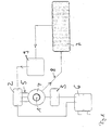
- FIG. 1 shows the circuit of an asynchronous motor 1 with a main winding 2 and an auxiliary winding 3 is shown schematically, the auxiliary winding in two Parts is divided and has a capacitor connected in series.
- the main winding is a switching unit which is arranged by means of three lines 5 the auxiliary winding completely, half or not at all in series with the main winding can switch.
- the switching processes are made using three AC switches, e.g. carried out by means of TRIAC's.
- the TRIAC's will actuated via a gate current acting on the control connection (gate). So three engine power levels are implemented.
- the stator 4 of the main 2 and Auxiliary winding 3 is only shown schematically as a circle.
- the windings are supplied with the mains voltage via a terminal box 6.
- Control logic 7 is used to determine the system size available, which taps the current in a winding via a line 8 and by means of comparators, not shown, with the specified values of Compares tolerance ranges.
- the output signal of the control logic 7 is one Switching module 9 supplied, which carries out the switching of the TRIAC's. Control logic 7 and switching module 9 together form a control module.
- the characteristic curve field is driven by such a motor Pump shown, the flow Q is plotted against the head H.
- the three characteristic curves 10 each represent a power level of Pump.
- Tolerance ranges are also drawn in the characteristic field, where tolerance ranges 11 with a high setting value (broken curves) and around tolerance ranges 12 with a low setting value (continuous curves) is. According to the invention, within the tolerance ranges Move system size.
- the flow can be measured directly as a system variable with a small flow rate with a low power level 10a becomes. If the flow increases due to an increased system requirement, then the maximum 13 of the tolerance range is detected on the falling characteristic curve 10a and switched one step up to the middle power step 10b. With another Increase the performance level 10c is reached.
- the setting value comparatively high like the slope of the connecting curve 14 of the maxima shows.
- the slope of this curve is set by the user.
- the user can also make an offset 17 pretend.
Landscapes
- Engineering & Computer Science (AREA)
- Power Engineering (AREA)
- Control Of Non-Positive-Displacement Pumps (AREA)
- Control Of Direct Current Motors (AREA)
Abstract
Description
- Figur 1
- das Schaltschema eines Elektromotors und
- Figur 2
- ein Kennlinienfeld.
Claims (11)
- Verfahren zum Betrieb eines Elektromotors (1), insbesondere eines Asynchronmotors, mit einer Hauptwicklung (2) und mit einer Hilfswicklung (3), die, um unterschiedliche diskrete Leistungsstufen (10) zu erhalten, über Stromschalter ganz oder teilweise in Serie zur Hauptwicklung (2) geschaltet wird, wobei ein Stromschalter vermittels eines einen Steueranschluß (Gate) beaufschlagenden Gatestromes betätigt wird,
dadurch gekennzeichnet,daß für jede Leistunsstufe ein Toleranzbereich (11,12) für eine bestimmte Systemgröße definiert wird,daß die Systemgröße gemessen wird unddaß die Leistungsstufe (10) durch eine Schalteinheit (9) automatisch geändert wird, wenn die Systemgröße aus dem Toleranzbereich (11,12) herausfällt. - Verfahren nach Anspruch 1,
dadurch gekennzeichnet, daß die Systemgröße eine Betriebsgröße des Elektromotors (1) ist, die eine Abhängigkeit von der Leistungsaufnahme aufweist. - Verfahren nach Anspruch 1 oder 2,
dadurch gekennzeichnet, daß als Systemgröße die Stromaufnahme oder eine Phasenverschiebung zwischen dem Strom in einer Motorwicklung und dem Strom des Netzes gemessen wird. - Elektromotor nach einem der vorherigen Ansprüche,
dadurch gekennzeichnet, daß die Stromschalter von TRIAC's gebildet werden. - Elektromotor nach einem der vorherigen Ansprüche,
dadurch gekennzeichnet, daß die Systemgröße kontinuierlich mittels eines analogen Bauteiles durch Abgriff gemessen wird. - Elektromotor nach einem der vorherigen Ansprüche,
dadurch gekennzeichnet, daß der Vergleich der abgegriffenen Systemgröße mit dem Toleranzbereich (11,12) durch ein analoges Bauteil vorgenommen wird. - Verfahren nach einem der vorherigen Ansprüche,
dadurch gekennzeichnet, daß mit dem Elektromotor (1) eine Kreiselpumpe, insbesondere eine Spaltrohrpumpe, betrieben wird. - Verfahren nach Anspruch 7,
dadurch gekennzeichnet, daß für jede Leistungsstufe der Kreiselpumpe die Förderkennlinie(10) als Förderhöhe in Abhängigkeit vom Durchfluß, aufgenommen wird, daß auf jeder Förderkennlinie (10) ein Toleranzbereich (11,12) überein Durchflußintervall (Q) definiert wird, daß eine mit dem Durchfluß Q korrespondierende Systemgröße gemessen und daß die Leistungsstufe so eingestellt wird, daß die Systemgröße in einen definierten Toleranzbereich (11,12) fällt. - Verfahren nach Anspruch 7 oder 8,
dadurch gekennzeichnet, daß auf den Förderkennlinien (10) Punkte von maximalem Durchfluß (Maxima) festgelegt werden, die Toleranzbereiche einseitig begrenzen, wobei die Maxima auf einer Kurve bestimmter Steigung liegen. - Verfahren nach Anspruch 9,
dadurch gekennzeichnet, daß bei der Kurve die Steigung und/oder ein Offset (17) vorgebbar ist. - Kreiselpumpe, insbesondere Spalttopfpumpe, angetrieben von einem in seiner Leistung in diskreten Stufen einstellbaren Asynchronmotor (1) mit einer Hauptwicklung (2) und mit einer Hilfswicklung (3), die über mindestens einen Stromschalter ganz oder teilweise in Serie zur Hauptwicklung (2) schaltbar ist, wobei ein Stromschalter vermittels eines einen Steueranschluß (Gate) beaufschlagenden Gatestromes betätigt wird und wobei jede Leistungsstufe durch eine Förderkennlinie (10) charakterisiert ist, gekennzeichnet durch
ein Steuermodul, das als Eingangsgröße eine Systemgröße empfängt und das mit einer Ausgangsgröße den Schalter schaltet.
Applications Claiming Priority (2)
| Application Number | Priority Date | Filing Date | Title |
|---|---|---|---|
| DE2001160203 DE10160203A1 (de) | 2001-12-07 | 2001-12-07 | Selbsttätige Leistungsstufenanpassung |
| DE10160203 | 2001-12-07 |
Publications (2)
| Publication Number | Publication Date |
|---|---|
| EP1322024A2 true EP1322024A2 (de) | 2003-06-25 |
| EP1322024A3 EP1322024A3 (de) | 2004-01-07 |
Family
ID=7708409
Family Applications (1)
| Application Number | Title | Priority Date | Filing Date |
|---|---|---|---|
| EP02025952A Withdrawn EP1322024A3 (de) | 2001-12-07 | 2002-11-21 | Selbsttätige Leistungsstufenanpassung |
Country Status (2)
| Country | Link |
|---|---|
| EP (1) | EP1322024A3 (de) |
| DE (1) | DE10160203A1 (de) |
Families Citing this family (3)
| Publication number | Priority date | Publication date | Assignee | Title |
|---|---|---|---|---|
| DE102009040259B4 (de) | 2009-09-04 | 2025-01-16 | Vitesco Technologies Germany Gmbh | Kühlanordnung und Verfahren zum Kühlen eines Getriebes |
| DE102022100246A1 (de) | 2022-01-06 | 2023-07-06 | KSB SE & Co. KGaA | Verfahren zum energieoptimierten Betrieb einer Pumpe |
| CN120830619B (zh) * | 2025-09-15 | 2025-11-18 | 江苏翔宇灌溉设备有限公司 | 基于负载动态感知的液压泵功率自适应控制方法及系统 |
Family Cites Families (9)
| Publication number | Priority date | Publication date | Assignee | Title |
|---|---|---|---|---|
| DE2910966A1 (de) * | 1979-03-21 | 1980-10-02 | Bosch Gmbh Robert | Kaelteverdichter |
| DE3733396C2 (de) * | 1987-10-02 | 1998-12-17 | Rexroth Mannesmann Gmbh | Elektrische Pumpenregelung für die Förderstrom- und Druckregelung an einem Verbraucher |
| DE3914342A1 (de) * | 1989-04-29 | 1990-11-08 | Grundfos Int | Pumpenaggregat |
| DE4031708C2 (de) * | 1990-10-06 | 1996-05-15 | Telefunken Microelectron | Verfahren zur Differenzdruckregelung eines von einem Einphasen-Kondensatormotor angetriebenen Pumpsystems und Schaltungsanordnung zur Durchführung des Verfahrens |
| DE4310786A1 (de) * | 1993-03-27 | 1994-10-27 | Hagemeier Kaethe | Verfahren und Vorrichtung zum geräuscharmen Betrieb eines Wechselstromerzeugers |
| DE4337614A1 (de) * | 1993-11-04 | 1995-05-11 | Telefunken Microelectron | Differenzdruckregelung für ein Pumpsystem |
| DE19642098A1 (de) * | 1996-10-12 | 1998-04-16 | Leybold Vakuum Gmbh | Antrieb für eine ölgedichtete Vakuumpumpe |
| DE19642097A1 (de) * | 1996-10-12 | 1998-04-16 | Leybold Vakuum Gmbh | Antrieb für eine ölgedichtete Vakuumpumpe, insbesondere Drehschiebervakuumpumpe |
| DE19815232A1 (de) * | 1998-04-04 | 1999-10-07 | Grundfos As | Verfahren zur Erfassung eines Parameters eines Asynchronmotors |
-
2001
- 2001-12-07 DE DE2001160203 patent/DE10160203A1/de not_active Withdrawn
-
2002
- 2002-11-21 EP EP02025952A patent/EP1322024A3/de not_active Withdrawn
Also Published As
| Publication number | Publication date |
|---|---|
| DE10160203A1 (de) | 2003-06-18 |
| EP1322024A3 (de) | 2004-01-07 |
Similar Documents
| Publication | Publication Date | Title |
|---|---|---|
| EP0242387B1 (de) | Kollektorloser gleichstrommotor, treiberschaltung für einen kollektorlosen gleichstrommotor sowie verfahren zum betrieb eines kollektorlosen gleichstrommotors | |
| DE3934139C2 (de) | Elektronische Steuerschaltung für einen bürstenlosen Gleichstrommotor | |
| DE10158994A1 (de) | Motortyp mit variabler Spulenwicklungszahl und Verfahren zur Veränderung der Spulenwicklungsanzahl zum Regeln einer Kühl- und Heizkapazität eines Kolbenverdichters | |
| DE19615072A1 (de) | Verfahren zum Steuern oder Regeln eines Elektromotors, und Anordnung zur Durchführung eines solchen Verfahrens | |
| EP1670135B1 (de) | Verfahren zum Betrieb einer rotierenden elektrischen Maschine | |
| DE10296460T5 (de) | Motoraktuator mit Momentregelung | |
| EP0671812B1 (de) | Schaltungsanordnung zur Drehzahlregelung von Elektromotoren | |
| DE10160203A1 (de) | Selbsttätige Leistungsstufenanpassung | |
| EP0601352B1 (de) | Bremseinrichtung für einen Reihenschluss-Kommutatormotor | |
| WO1996002971A1 (de) | Drehzahlverstellbarer ec-gleichstrommotor | |
| WO2012104169A2 (de) | Anordnung zur ansteuerung einer elektrischen vakuum-pumpe | |
| EP1589652A1 (de) | Verfahren zur Ansteuerung eines bürstenlosen Elektromotors | |
| EP0948126B1 (de) | Verfahren zur Erfassung eines Parameters eines Asynchronmotors | |
| EP0106849B1 (de) | Anlassvorrichtung für elektromotoren und verfahren zu deren betrieb | |
| DE60107926T2 (de) | Motor-Startschaltung, insbesondere für Kühlschrankkompressoren, mit verbesserten Eigenschaften | |
| DE10307823B4 (de) | Schaltungsanordnung zur Lüfterregelung | |
| EP0635927B1 (de) | Permanentmagnet-Gleichstrommotor | |
| DE4307096C2 (de) | Verfahren zum Ansteuern eines wechselstromgespeisten Einphaseninduktionsmotors | |
| DE19850905A1 (de) | Vorrichtung zur Leistungssteuerung | |
| DE19844844C2 (de) | Kreiselpumpenaggregat | |
| WO1988008221A1 (fr) | Circuit pour actionner un petit moteur monophase sans balai dans le reseau a tension continue de vehicules automobiles | |
| DE2633047C3 (de) | Kollektorloser Gleichstrommotor mit mehreren in Stern geschalteten Phasenwicklungen | |
| EP0545087A1 (de) | Mehrtouriger Einphasenmotor | |
| DE373372C (de) | Regelungseinrichtung fuer elektrische Motoren | |
| DE4222431A1 (de) | Vorrichtung zur Wicklungsumschaltung eines Einphasen-Elektromotors |
Legal Events
| Date | Code | Title | Description |
|---|---|---|---|
| PUAI | Public reference made under article 153(3) epc to a published international application that has entered the european phase |
Free format text: ORIGINAL CODE: 0009012 |
|
| AK | Designated contracting states |
Designated state(s): AT BE BG CH CY CZ DE DK EE ES FI FR GB GR IE IT LI LU MC NL PT SE SK TR |
|
| AX | Request for extension of the european patent |
Extension state: AL LT LV MK RO SI |
|
| PUAL | Search report despatched |
Free format text: ORIGINAL CODE: 0009013 |
|
| AK | Designated contracting states |
Kind code of ref document: A3 Designated state(s): AT BE BG CH CY CZ DE DK EE ES FI FR GB GR IE IT LI LU MC NL PT SE SK TR |
|
| AX | Request for extension of the european patent |
Extension state: AL LT LV MK RO SI |
|
| RIC1 | Information provided on ipc code assigned before grant |
Ipc: 7F 04B 49/06 B Ipc: 7H 02P 7/622 B Ipc: 7H 02K 17/08 A |
|
| AKX | Designation fees paid | ||
| REG | Reference to a national code |
Ref country code: DE Ref legal event code: 8566 |
|
| STAA | Information on the status of an ep patent application or granted ep patent |
Free format text: STATUS: THE APPLICATION IS DEEMED TO BE WITHDRAWN |
|
| 18D | Application deemed to be withdrawn |
Effective date: 20040708 |