EP1321990A2 - Zusammengesetzte Batterie, zusammengesetztes Batteriemodul und Fahrzeug mit zusammengesetzter Batterie oder zusammengesetztem Batteriemodul - Google Patents
Zusammengesetzte Batterie, zusammengesetztes Batteriemodul und Fahrzeug mit zusammengesetzter Batterie oder zusammengesetztem Batteriemodul Download PDFInfo
- Publication number
- EP1321990A2 EP1321990A2 EP20020025283 EP02025283A EP1321990A2 EP 1321990 A2 EP1321990 A2 EP 1321990A2 EP 20020025283 EP20020025283 EP 20020025283 EP 02025283 A EP02025283 A EP 02025283A EP 1321990 A2 EP1321990 A2 EP 1321990A2
- Authority
- EP
- European Patent Office
- Prior art keywords
- batteries
- cooling air
- assembled battery
- flow
- assembled
- Prior art date
- Legal status (The legal status is an assumption and is not a legal conclusion. Google has not performed a legal analysis and makes no representation as to the accuracy of the status listed.)
- Withdrawn
Links
- 238000001816 cooling Methods 0.000 claims description 52
- 238000007664 blowing Methods 0.000 claims description 34
- HBBGRARXTFLTSG-UHFFFAOYSA-N Lithium ion Chemical compound [Li+] HBBGRARXTFLTSG-UHFFFAOYSA-N 0.000 description 11
- 229910001416 lithium ion Inorganic materials 0.000 description 11
- 239000011149 active material Substances 0.000 description 9
- 239000000463 material Substances 0.000 description 9
- 230000000052 comparative effect Effects 0.000 description 6
- OKTJSMMVPCPJKN-UHFFFAOYSA-N Carbon Chemical compound [C] OKTJSMMVPCPJKN-UHFFFAOYSA-N 0.000 description 5
- 230000007423 decrease Effects 0.000 description 5
- 239000012212 insulator Substances 0.000 description 5
- 239000007784 solid electrolyte Substances 0.000 description 5
- 238000009826 distribution Methods 0.000 description 4
- 239000004743 Polypropylene Substances 0.000 description 3
- 230000015556 catabolic process Effects 0.000 description 3
- 238000006731 degradation reaction Methods 0.000 description 3
- 239000003792 electrolyte Substances 0.000 description 3
- 239000008151 electrolyte solution Substances 0.000 description 3
- 238000011156 evaluation Methods 0.000 description 3
- 229910052744 lithium Inorganic materials 0.000 description 3
- -1 lithium transition metal compound Chemical class 0.000 description 3
- 230000005855 radiation Effects 0.000 description 3
- OIFBSDVPJOWBCH-UHFFFAOYSA-N Diethyl carbonate Chemical compound CCOC(=O)OCC OIFBSDVPJOWBCH-UHFFFAOYSA-N 0.000 description 2
- KMTRUDSVKNLOMY-UHFFFAOYSA-N Ethylene carbonate Chemical compound O=C1OCCO1 KMTRUDSVKNLOMY-UHFFFAOYSA-N 0.000 description 2
- WHXSMMKQMYFTQS-UHFFFAOYSA-N Lithium Chemical compound [Li] WHXSMMKQMYFTQS-UHFFFAOYSA-N 0.000 description 2
- PXHVJJICTQNCMI-UHFFFAOYSA-N Nickel Chemical compound [Ni] PXHVJJICTQNCMI-UHFFFAOYSA-N 0.000 description 2
- 239000004698 Polyethylene Substances 0.000 description 2
- 239000003575 carbonaceous material Substances 0.000 description 2
- 229920000573 polyethylene Polymers 0.000 description 2
- 229920001155 polypropylene Polymers 0.000 description 2
- 238000003466 welding Methods 0.000 description 2
- RYGMFSIKBFXOCR-UHFFFAOYSA-N Copper Chemical compound [Cu] RYGMFSIKBFXOCR-UHFFFAOYSA-N 0.000 description 1
- 229910032387 LiCoO2 Inorganic materials 0.000 description 1
- 229910001290 LiPF6 Inorganic materials 0.000 description 1
- 239000006230 acetylene black Substances 0.000 description 1
- 229910052782 aluminium Inorganic materials 0.000 description 1
- XAGFODPZIPBFFR-UHFFFAOYSA-N aluminium Chemical compound [Al] XAGFODPZIPBFFR-UHFFFAOYSA-N 0.000 description 1
- 239000002194 amorphous carbon material Substances 0.000 description 1
- 229910021383 artificial graphite Inorganic materials 0.000 description 1
- 239000000470 constituent Substances 0.000 description 1
- 238000010276 construction Methods 0.000 description 1
- 229910052802 copper Inorganic materials 0.000 description 1
- 239000010949 copper Substances 0.000 description 1
- 239000013078 crystal Substances 0.000 description 1
- 230000003247 decreasing effect Effects 0.000 description 1
- 230000000593 degrading effect Effects 0.000 description 1
- 238000009792 diffusion process Methods 0.000 description 1
- QHGJSLXSVXVKHZ-UHFFFAOYSA-N dilithium;dioxido(dioxo)manganese Chemical compound [Li+].[Li+].[O-][Mn]([O-])(=O)=O QHGJSLXSVXVKHZ-UHFFFAOYSA-N 0.000 description 1
- 230000000694 effects Effects 0.000 description 1
- 229910002804 graphite Inorganic materials 0.000 description 1
- 239000010439 graphite Substances 0.000 description 1
- 230000005484 gravity Effects 0.000 description 1
- 229910021385 hard carbon Inorganic materials 0.000 description 1
- 230000020169 heat generation Effects 0.000 description 1
- 229910003480 inorganic solid Inorganic materials 0.000 description 1
- 239000010416 ion conductor Substances 0.000 description 1
- GLNWILHOFOBOFD-UHFFFAOYSA-N lithium sulfide Chemical compound [Li+].[Li+].[S-2] GLNWILHOFOBOFD-UHFFFAOYSA-N 0.000 description 1
- 238000000034 method Methods 0.000 description 1
- 239000011259 mixed solution Substances 0.000 description 1
- 238000012986 modification Methods 0.000 description 1
- 230000004048 modification Effects 0.000 description 1
- 229910021382 natural graphite Inorganic materials 0.000 description 1
- 229910052759 nickel Inorganic materials 0.000 description 1
- 230000000379 polymerizing effect Effects 0.000 description 1
- 239000011148 porous material Substances 0.000 description 1
- 239000000843 powder Substances 0.000 description 1
- 229910021384 soft carbon Inorganic materials 0.000 description 1
- 238000005476 soldering Methods 0.000 description 1
- 239000000243 solution Substances 0.000 description 1
- 239000002203 sulfidic glass Substances 0.000 description 1
Images


Classifications
-
- H—ELECTRICITY
- H01—ELECTRIC ELEMENTS
- H01M—PROCESSES OR MEANS, e.g. BATTERIES, FOR THE DIRECT CONVERSION OF CHEMICAL ENERGY INTO ELECTRICAL ENERGY
- H01M10/00—Secondary cells; Manufacture thereof
- H01M10/60—Heating or cooling; Temperature control
- H01M10/65—Means for temperature control structurally associated with the cells
- H01M10/655—Solid structures for heat exchange or heat conduction
- H01M10/6553—Terminals or leads
-
- H—ELECTRICITY
- H01—ELECTRIC ELEMENTS
- H01M—PROCESSES OR MEANS, e.g. BATTERIES, FOR THE DIRECT CONVERSION OF CHEMICAL ENERGY INTO ELECTRICAL ENERGY
- H01M10/00—Secondary cells; Manufacture thereof
- H01M10/60—Heating or cooling; Temperature control
- H01M10/61—Types of temperature control
- H01M10/613—Cooling or keeping cold
-
- H—ELECTRICITY
- H01—ELECTRIC ELEMENTS
- H01M—PROCESSES OR MEANS, e.g. BATTERIES, FOR THE DIRECT CONVERSION OF CHEMICAL ENERGY INTO ELECTRICAL ENERGY
- H01M10/00—Secondary cells; Manufacture thereof
- H01M10/60—Heating or cooling; Temperature control
- H01M10/65—Means for temperature control structurally associated with the cells
- H01M10/651—Means for temperature control structurally associated with the cells characterised by parameters specified by a numeric value or mathematical formula, e.g. ratios, sizes or concentrations
- H01M10/652—Means for temperature control structurally associated with the cells characterised by parameters specified by a numeric value or mathematical formula, e.g. ratios, sizes or concentrations characterised by gradients
-
- H—ELECTRICITY
- H01—ELECTRIC ELEMENTS
- H01M—PROCESSES OR MEANS, e.g. BATTERIES, FOR THE DIRECT CONVERSION OF CHEMICAL ENERGY INTO ELECTRICAL ENERGY
- H01M10/00—Secondary cells; Manufacture thereof
- H01M10/60—Heating or cooling; Temperature control
- H01M10/65—Means for temperature control structurally associated with the cells
- H01M10/655—Solid structures for heat exchange or heat conduction
- H01M10/6551—Surfaces specially adapted for heat dissipation or radiation, e.g. fins or coatings
-
- H—ELECTRICITY
- H01—ELECTRIC ELEMENTS
- H01M—PROCESSES OR MEANS, e.g. BATTERIES, FOR THE DIRECT CONVERSION OF CHEMICAL ENERGY INTO ELECTRICAL ENERGY
- H01M10/00—Secondary cells; Manufacture thereof
- H01M10/60—Heating or cooling; Temperature control
- H01M10/65—Means for temperature control structurally associated with the cells
- H01M10/656—Means for temperature control structurally associated with the cells characterised by the type of heat-exchange fluid
- H01M10/6561—Gases
- H01M10/6563—Gases with forced flow, e.g. by blowers
-
- H—ELECTRICITY
- H01—ELECTRIC ELEMENTS
- H01M—PROCESSES OR MEANS, e.g. BATTERIES, FOR THE DIRECT CONVERSION OF CHEMICAL ENERGY INTO ELECTRICAL ENERGY
- H01M50/00—Constructional details or processes of manufacture of the non-active parts of electrochemical cells other than fuel cells, e.g. hybrid cells
- H01M50/50—Current conducting connections for cells or batteries
- H01M50/502—Interconnectors for connecting terminals of adjacent batteries; Interconnectors for connecting cells outside a battery casing
- H01M50/503—Interconnectors for connecting terminals of adjacent batteries; Interconnectors for connecting cells outside a battery casing characterised by the shape of the interconnectors
-
- H—ELECTRICITY
- H01—ELECTRIC ELEMENTS
- H01M—PROCESSES OR MEANS, e.g. BATTERIES, FOR THE DIRECT CONVERSION OF CHEMICAL ENERGY INTO ELECTRICAL ENERGY
- H01M50/00—Constructional details or processes of manufacture of the non-active parts of electrochemical cells other than fuel cells, e.g. hybrid cells
- H01M50/50—Current conducting connections for cells or batteries
- H01M50/502—Interconnectors for connecting terminals of adjacent batteries; Interconnectors for connecting cells outside a battery casing
- H01M50/507—Interconnectors for connecting terminals of adjacent batteries; Interconnectors for connecting cells outside a battery casing comprising an arrangement of two or more busbars within a container structure, e.g. busbar modules
-
- H—ELECTRICITY
- H01—ELECTRIC ELEMENTS
- H01M—PROCESSES OR MEANS, e.g. BATTERIES, FOR THE DIRECT CONVERSION OF CHEMICAL ENERGY INTO ELECTRICAL ENERGY
- H01M10/00—Secondary cells; Manufacture thereof
- H01M10/60—Heating or cooling; Temperature control
- H01M10/62—Heating or cooling; Temperature control specially adapted for specific applications
- H01M10/625—Vehicles
-
- Y—GENERAL TAGGING OF NEW TECHNOLOGICAL DEVELOPMENTS; GENERAL TAGGING OF CROSS-SECTIONAL TECHNOLOGIES SPANNING OVER SEVERAL SECTIONS OF THE IPC; TECHNICAL SUBJECTS COVERED BY FORMER USPC CROSS-REFERENCE ART COLLECTIONS [XRACs] AND DIGESTS
- Y02—TECHNOLOGIES OR APPLICATIONS FOR MITIGATION OR ADAPTATION AGAINST CLIMATE CHANGE
- Y02E—REDUCTION OF GREENHOUSE GAS [GHG] EMISSIONS, RELATED TO ENERGY GENERATION, TRANSMISSION OR DISTRIBUTION
- Y02E60/00—Enabling technologies; Technologies with a potential or indirect contribution to GHG emissions mitigation
- Y02E60/10—Energy storage using batteries
Definitions
- the present invention relates to an assembled battery formed by connecting a plurality of batteries one another in parallel or in series, an assembled battery module using the batteries and a vehicle using the assembled battery or using the assembled battery module as a power source.
- an assembled battery for example, there has been an assembled battery formed by connecting a plurality of the same batteries one another in series as disclosed in Japanese Patent Application Laid-Open No. H10-64598.
- the assembled battery is equipped with a cooling fan cooling the batteries.
- Such an assembled battery discloses that the cooling fan is activated when temperature of the assembled battery increases and that the cooling fan is stopped when the temperature decreases.
- the batteries are set in an appropriate temperature range, whereby achieving efficient utilization of the batteries.
- FIG. 1A is a graph showing temperature distributions in both windward and leeward of the assembled battery in the case of providing terminals on the leeward battery.
- 1B is a graph showing temperature distributions in windward and leeward of the assembled battery in the case of providing terminals on the windward battery. Generated heat from the leeward battery in the case of providing the terminals on the leeward battery is higher than that of the leeward battery in the case of providing the terminals on the windward battery. Further, when no air is blown from the windward toward the leeward (during stoppage of a vehicle), temperature difference between the windward and the leeward is increased, thereby degrading the insides of the batteries rapidly.
- an object of the present invention to provide an assembled battery capable of preventing an output decrease of the entire assembled battery, which is caused by temperature differences among respective batteries constituting the assembled battery.
- the inventors of the present invention assiduously examined means for achieving the foregoing object. Consequently, the inventors found out that an assembled battery including a plurality of batteries connected in parallel or in series, in which rugged portions having at least one shape of triangular prism, cuboid, semisphere and hole are provided on connection portions between the batteries, could attain the foregoing object.
- An aspect of the present invention provides an assembled battery comprising: a plurality of batteries connected in any of parallel and series; terminals for taking out an output of the plurality of batteries; bus bars for connecting the batteries one another; and rugged portions provided on the bus bars, the rugged portions having at least one shape selected from the group consisting of: a triangular prism; a cuboid; a semisphere; and a hole shape.
- FIGS. 2 and 3 are cross-sectional and plan views showing an internal structure of an assembled battery 1 of the present invention, respectively.
- the assembled battery 1 includes laminated batteries 2, terminals 3, rugged portions 4, air blowing means 7, heat insulators 11 and bus bars 12.
- the terminals 3 take out an output of the laminated batteries 2.
- the rugged portions 4 are provided on surfaces or in internal portions of the bus bars 12.
- the air blowing means 7 blows cooling air to the laminated batteries 2, thereby cooling surfaces of the laminated batteries 2.
- the heat insulators 11 absorb the heat radiated from the laminated batteries 2 and prevent the heat from being discharged to the outside of the assembled battery 1.
- the bus bars 12 connect respective electrodes 2b, 2b of each of the laminated batteries 2 one another (refer to FIGS. 4A and 4B).
- upper and lower surfaces of each of the electrodes 2b are joined to upper and lower bus bars 12, 12, respectively.
- Joint portions between the electrodes 2b and the bus bars 12 do not need to be provided on both of the upper and lower sides, but may be provided only on any of the upper and lower sides.
- the joining method is not particularly limited to these.
- Each of the batteries 2 for use in the present invention is constituted by a battery body 2a and the electrodes 2b.
- the electrodes 2b are formed on one side and an opposite side of the battery body 2a.
- the battery 2 is not limited to this battery shape.
- the electrodes 2b may be provided on one side of the battery body 2a.
- the battery 2 of the present invention employs a lithium ion secondary battery.
- the lithium ion secondary battery includes positive and negative electrodes, active materials for the positive and negative electrodes, separators, an electrolyte and the like as main constituent components.
- a base material containing aluminum as a main component is suitably used.
- a base material containing copper or nickel as a main component is suitably used.
- the active material for the positive electrodes is formed on a surface of the base material for the positive electrodes.
- an active material obtained by mixing carbon powder such as acetylene black and graphite powder with lithium transition metal compound such as lithium manganate (LiMn 2 O 4 ), lithium cobaltate (LiCoO 2 ) and lithium nickelate (LiNiO 2 ) is suitably used.
- the mixed active material can improve electrical conductivity of the positive electrodes.
- the active material for the negative electrodes is formed on a surface of the base material for the negative electrodes.
- the active material for the negative electrodes is composed of 1) amorphous carbon material such as soft carbon and hard carbon or 2) active material powder such as carbon powder of natural graphite and the like.
- highly graphitized carbon material such as graphite and artificial graphite has features as follows: diffusion of lithium ions in crystals of the material is easy, a specific gravity of the material is large, and a ratio of lithium ions storable per unit weight of the material is large, the lithium ions contributing to charge/discharge of the battery. It is preferable to use the highly graphitized carbon material as the active material for the negative electrodes.
- a film made into a three-layer structure is preferable, which is obtained by sandwiching a lithium-ion permeable polyethylene (PE) film having micro pores between porous lithium-ion permeable polypropylene (PP) films.
- PE lithium-ion permeable polyethylene
- PP polypropylene
- an electrolyte solution as a lithium-ion conductor is required.
- an electrolyte solution a solution obtained by dissolving an electrolyte of LiPF 6 into mixed solution in which ethylene carbonate (EC) is mixed with diethyl carbonate (DEC) is suitably used.
- a foil-shaped or plate-shaped solid electrolyte instead of the electrolyte solution.
- this solid electrolyte a pseudo-solid electrolyte obtained by polymerizing or pectizing the above-described electrolyte, an organic solid electrolyte having lithium-ion conductivity, or an inorganic solid electrolyte such as lithium sulfide glass is cited.
- the batteries 2 are sandwiched by the heat insulators 11 in the vertical direction such that each of intervals H between the heat insulators 11 and the batteries 2 is about 10 mm. Cooling air is blown to this interval H.
- the assembled battery is not limited to these conditions.
- the plurality of rugged portions 4 are provided on the surfaces of the bus bars 12 opposing to the heat insulators 11.
- the cooling air is efficiently blown to the bus bars 12 by these rugged portions 4.
- surface area of the bus bars 12 is increased, thereby making it possible to enhance heat radiation efficiency of the bus bars 12.
- wind direction described below is defined as a direction of air flow blown from the air blowing means 7 to the batteries 2.
- triangular prisms 41 are arranged on each of bus bars 12 as the connection portion between the batteries 2.
- triangular prisms 45 are arranged on each of bus bars 12 as the connection portion between the batteries 2. A setting is made such that heights of the triangular prisms 45 increase from the windward toward the leeward.
- cuboids 46 are arranged on each of bus bars 12 as the connection portion between the batteries 2. A setting is made such that heights of the cuboids 46 increase from the windward toward the leeward.
- semispherical convex portions 47 are arranged on each of bus bars 12 as the connection portion between the batteries 2. A setting is made such that sizes of the semispherical convex portions 47 increase from the windward toward the leeward.
- hole-shaped concave portions 48 are arranged in each of bus bars 12 as the connection portion between the batteries. A setting is made such that sizes of the hole-shaped concave portions 48 increase from the windward toward the leeward.
- triangular prisms 49 are arranged on each of bus bars 12 as the connection portion between the batteries 2. A setting is made such that densities of the triangular prisms 49 increase from the windward toward the leeward.
- cuboids 50 are arranged on each of bus bars 12 as the connection portion between the batteries 2.
- a setting is made such that densities of the cuboids 50 increase from the windward toward the leeward.
- semispherical convex portions 51 are arranged on each of bus bars 12 as the connection portion between the batteries 2. A setting is made such that densities of the semispherical convex portions 51 increase from the windward toward the leeward.
- hole-shaped concave portions 52 are arranged in each of bus bars 12 as the connection portion between the batteries 2. A setting is made such that densities of the hole-shaped concave portions 52 increase from the windward toward the leeward.
- cuboids 53 are arranged on each of bus bars 12 as the connection portion between the batteries 2.
- a setting is made such that the angles (e.g., ⁇ u, ⁇ d) of the major axes of the cuboids 53 to the wind direction increase from the windward toward the leeward.
- the heat radiation characteristics of the batteries of the examples are improved as compared with those of the batteries having flat connection portions since the surface areas of the terminal portions are expanded.
- the temperatures of the leeward batteries of the examples are decreased to 45°C on average, and thus the effectiveness of the present invention was made apparent.
- the temperature increase of the leeward was restricted with respect to the windward and that temperature differences among the respective batteries were reduced, and thus the effectiveness of the present invention was made far more apparent.
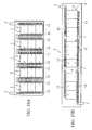
- FIGS. 19A and 19B show an assembled battery module 5 using the above-described assembled batteries 1.
- the assembled battery module 5 shown in FIG. 19A is configured such that five assembled batteries 1 shown in FIGS. 2 and 3 are connected in series, and obtains a high output.
- the assembled battery module 5 shown in FIG. 19B is configured such that assembled batteries 1 shown in FIGS. 2 and 3 are connected in parallel, and obtains a high output.
- FIG. 20 shows a vehicle 6 in which the assembled batteries 1 or the assembled battery module 5 is mounted.
- the assembled battery module 5 or the vehicle 6 attains a high output and a long lifetime due to the above-described effects of the present invention.
- an assembled battery which is characterized in that the rugged portions having at least one shape of triangular prism, cuboid, semisphere and hole shape are provided at connecting portions connecting the batteries one another in parallel or in series.
- the rugged portions having such a shape are provided at the connecting portions, thus making it possible to increase surface area of the bus bars and to improve the heat radiation efficiency thereof. Therefore, the output decrease and degradation of the entire assembled battery can be prevented.
- Air is efficiently applied to the bus bars in the case of blowing the air from the air blowing means to the assembled battery of the present invention, thus making it possible to sufficiently control heat generation at the terminal portions in the case of charge/discharge of a large current from the batteries.
- heights of the foregoing rugged portions may increase toward the leeward direction with respect to the wind direction of the air blowing means, or densities of the rugged portions may increase similarly to the above.
- angles of the major axis direction to a direction parallel to the wind direction may increase similarly. With such a structure, air is efficiently applied to the leeward batteries.
- the temperature differences in the entire assembled battery can be reduced, whereby the output decrease and degradation of the entire assembled battery can be prevented.
- the air blowing means may be used air blowing means such as a general cooling fan may be used, or air blowing means in which air is taken from outside of the vehicle during vehicle running and the like. No particular limitations are imposed on the air blowing means.
- the assembled batteries or the assembled battery module of the present invention is mounted in the vehicle, thereby a high-output vehicle that has high stability in supply of electric power can be provided.
- the assembled batteries in which temperature differences are small can be obtained by changing size and density of the rugged portions, such that lifetime of the batteries can be improved.
Landscapes
- Chemical & Material Sciences (AREA)
- Chemical Kinetics & Catalysis (AREA)
- Electrochemistry (AREA)
- General Chemical & Material Sciences (AREA)
- Engineering & Computer Science (AREA)
- Manufacturing & Machinery (AREA)
- Physics & Mathematics (AREA)
- Algebra (AREA)
- General Physics & Mathematics (AREA)
- Mathematical Analysis (AREA)
- Mathematical Optimization (AREA)
- Pure & Applied Mathematics (AREA)
- Secondary Cells (AREA)
- Battery Mounting, Suspending (AREA)
- Connection Of Batteries Or Terminals (AREA)
Applications Claiming Priority (2)
| Application Number | Priority Date | Filing Date | Title |
|---|---|---|---|
| JP2001386714A JP2003187767A (ja) | 2001-12-19 | 2001-12-19 | 組電池、組電池モジュール及びそれらを備えた車両 |
| JP2001386714 | 2001-12-19 |
Publications (1)
| Publication Number | Publication Date |
|---|---|
| EP1321990A2 true EP1321990A2 (de) | 2003-06-25 |
Family
ID=19187965
Family Applications (1)
| Application Number | Title | Priority Date | Filing Date |
|---|---|---|---|
| EP20020025283 Withdrawn EP1321990A2 (de) | 2001-12-19 | 2002-11-12 | Zusammengesetzte Batterie, zusammengesetztes Batteriemodul und Fahrzeug mit zusammengesetzter Batterie oder zusammengesetztem Batteriemodul |
Country Status (3)
| Country | Link |
|---|---|
| US (1) | US20030124419A1 (de) |
| EP (1) | EP1321990A2 (de) |
| JP (1) | JP2003187767A (de) |
Cited By (2)
| Publication number | Priority date | Publication date | Assignee | Title |
|---|---|---|---|---|
| FR2876504A1 (fr) * | 2004-10-07 | 2006-04-14 | Yi Chieh Wu | Structure de ventilation interne de boitier de batterie pour controler la temperature regnant a l'interieur de celui-ci |
| DE102009015931B4 (de) | 2008-04-02 | 2023-08-10 | Denso Corporation | Batterieeinheit mit Gebläse |
Families Citing this family (21)
| Publication number | Priority date | Publication date | Assignee | Title |
|---|---|---|---|---|
| JP2003308817A (ja) * | 2002-04-17 | 2003-10-31 | Nissan Motor Co Ltd | 組電池 |
| JP4496728B2 (ja) * | 2003-08-11 | 2010-07-07 | 日産自動車株式会社 | 組電池冷却制御装置および車両 |
| JP5240963B2 (ja) * | 2003-10-01 | 2013-07-17 | 日産自動車株式会社 | 組電池 |
| JP4894129B2 (ja) * | 2003-10-10 | 2012-03-14 | 日産自動車株式会社 | 薄型電池及び組電池 |
| ATE526694T1 (de) * | 2003-10-28 | 2011-10-15 | Johnson Controls Tech Co | Batteriesystem mit verbesserter wärmeableitung |
| JP4617672B2 (ja) * | 2003-12-26 | 2011-01-26 | トヨタ自動車株式会社 | ラミネート電池モジュールとその製造方法 |
| KR100627335B1 (ko) * | 2004-06-25 | 2006-09-25 | 삼성에스디아이 주식회사 | 전지 모듈과 전지 모듈의 격벽 |
| JP4696511B2 (ja) * | 2004-09-21 | 2011-06-08 | 日産自動車株式会社 | バッテリ冷却システム |
| JP2006213072A (ja) * | 2005-02-01 | 2006-08-17 | Advics:Kk | 車両液圧制御装置 |
| CA2496092C (en) * | 2005-02-04 | 2007-11-13 | Li-Ho Yao | Battery pack |
| US7967506B2 (en) | 2005-03-16 | 2011-06-28 | Ford Global Technologies, Llc | Power supply temperature sensor and system |
| EP1875582B1 (de) * | 2005-03-16 | 2017-02-22 | Ford Global Technologies, LLC | Stromversorgungssystem mit temperatursensorstationen |
| US7604896B2 (en) * | 2005-03-16 | 2009-10-20 | Ford Global Technologies, Llc | High voltage battery assembly for a motor vehicle |
| KR100612239B1 (ko) | 2005-04-26 | 2006-08-11 | 삼성에스디아이 주식회사 | 이차 전지 모듈과 이차 전지 모듈을 이루는 이차 전지의격벽 |
| US20080299448A1 (en) * | 2006-11-20 | 2008-12-04 | Derrick Scott Buck | Battery unit with temperature control device |
| EP2343755A4 (de) * | 2008-11-07 | 2013-06-26 | Mitsubishi Heavy Ind Ltd | Sekundärbatterie-sammelschiene und sekundärbatteriemodul |
| JP5531450B2 (ja) * | 2009-05-08 | 2014-06-25 | 株式会社デンソー | 電池パック |
| US8729866B2 (en) | 2009-09-02 | 2014-05-20 | Toyota Jidosha Kabushiki Kaisha | Sulfide-based all-solid-state lithium secondary battery system |
| DE102011079394A1 (de) * | 2011-07-19 | 2013-01-24 | Siemens Aktiengesellschaft | Energiespeichermodul |
| DE102013015422B4 (de) * | 2013-09-18 | 2015-07-23 | Airbus Defence and Space GmbH | Kühlvorrichtung zur Kühlung von Batteriezellen, Batterievorrichtung sowie Kühlverfahren |
| WO2021024384A1 (ja) * | 2019-08-06 | 2021-02-11 | 三菱電機株式会社 | 電池モジュールおよび電池モジュールシステム |
Family Cites Families (1)
| Publication number | Priority date | Publication date | Assignee | Title |
|---|---|---|---|---|
| US4983475A (en) * | 1990-02-13 | 1991-01-08 | Delans Darwin D | Bar for connecting together two plate straps of the same polarity on an electrochemical battery |
-
2001
- 2001-12-19 JP JP2001386714A patent/JP2003187767A/ja active Pending
-
2002
- 2002-11-12 EP EP20020025283 patent/EP1321990A2/de not_active Withdrawn
- 2002-12-17 US US10/320,421 patent/US20030124419A1/en not_active Abandoned
Cited By (4)
| Publication number | Priority date | Publication date | Assignee | Title |
|---|---|---|---|---|
| FR2876504A1 (fr) * | 2004-10-07 | 2006-04-14 | Yi Chieh Wu | Structure de ventilation interne de boitier de batterie pour controler la temperature regnant a l'interieur de celui-ci |
| LU91164B1 (de) * | 2004-10-07 | 2006-11-16 | Yi-Chieh Wu | Akkukasten mit einer K}hlvorrichtung |
| NL1029593C2 (nl) * | 2004-10-07 | 2007-06-05 | Yi-Chieh Wu | In een accuhuis opgenomen ventilatie-constructie voor het regelen van de temperatuur daarin. |
| DE102009015931B4 (de) | 2008-04-02 | 2023-08-10 | Denso Corporation | Batterieeinheit mit Gebläse |
Also Published As
| Publication number | Publication date |
|---|---|
| US20030124419A1 (en) | 2003-07-03 |
| JP2003187767A (ja) | 2003-07-04 |
Similar Documents
| Publication | Publication Date | Title |
|---|---|---|
| EP1321990A2 (de) | Zusammengesetzte Batterie, zusammengesetztes Batteriemodul und Fahrzeug mit zusammengesetzter Batterie oder zusammengesetztem Batteriemodul | |
| EP1244170B1 (de) | Aufladbare Lithium Zelle und Verbindungsstruktur dafür | |
| US11876199B2 (en) | Battery module, battery pack comprising same battery module, and vehicle comprising same battery pack | |
| CN100544111C (zh) | 具有在电池单元之间的附着部件的电池模块 | |
| CN108028336B (zh) | 具有用于单元模块的稳定固定装置的电池模块组件 | |
| US10361469B2 (en) | Battery module having water-cooled type cooling structure | |
| JP4374947B2 (ja) | 冷却用タブを有する積層型バイポーラ二次電池 | |
| US8124276B2 (en) | Battery structure, assembled battery, and vehicle mounting these thereon | |
| KR101252944B1 (ko) | 방열 특성이 향상된 배터리 팩 | |
| US20160133999A1 (en) | Battery module assembly having coolant flow channel | |
| US20100003581A1 (en) | Electric power storage apparatus | |
| CN101150209A (zh) | 电源系统和电动车 | |
| CN103081173A (zh) | 电池组 | |
| KR102263457B1 (ko) | 냉각 효율성이 향상된 전지셀 | |
| KR20060000433A (ko) | 이차 전지 | |
| JP2000090976A (ja) | リチウム二次電池モジュール | |
| JP3838284B2 (ja) | 非水電解質二次電池 | |
| JP2008287916A (ja) | 電池パック | |
| KR102268336B1 (ko) | 냉각 효율성이 향상된 전지셀 | |
| KR20160087141A (ko) | 방열을 촉진하기 위한 개구부를 포함하는 전지셀 카트리지 및 이를 포함하는 전지모듈 | |
| KR102564098B1 (ko) | 하나 이상의 냉각 유체 흐름 오리피스를 포함하는 가요성 패키징을 갖는 전기화학 축전지, 특히 금속-이온 축전지, 연관된 모듈 및 제조 방법 | |
| US20200185691A1 (en) | Sealed battery and assembled battery | |
| JPH0896838A (ja) | リチウムイオン二次電池 | |
| JP7460773B2 (ja) | バッテリーモジュール、それを含むバッテリーパック及び自動車 | |
| JP2005209368A (ja) | 電池パック |
Legal Events
| Date | Code | Title | Description |
|---|---|---|---|
| PUAI | Public reference made under article 153(3) epc to a published international application that has entered the european phase |
Free format text: ORIGINAL CODE: 0009012 |
|
| 17P | Request for examination filed |
Effective date: 20021112 |
|
| AK | Designated contracting states |
Designated state(s): AT BE BG CH CY CZ DE DK EE ES FI FR GB GR IE IT LI LU MC NL PT SE SK TR |
|
| AX | Request for extension of the european patent |
Extension state: AL LT LV MK RO SI |
|
| STAA | Information on the status of an ep patent application or granted ep patent |
Free format text: STATUS: THE APPLICATION HAS BEEN WITHDRAWN |
|
| 18W | Application withdrawn |
Effective date: 20040504 |