EP1321908A2 - Système de contrôle de machine de vente - Google Patents
Système de contrôle de machine de vente Download PDFInfo
- Publication number
- EP1321908A2 EP1321908A2 EP02380262A EP02380262A EP1321908A2 EP 1321908 A2 EP1321908 A2 EP 1321908A2 EP 02380262 A EP02380262 A EP 02380262A EP 02380262 A EP02380262 A EP 02380262A EP 1321908 A2 EP1321908 A2 EP 1321908A2
- Authority
- EP
- European Patent Office
- Prior art keywords
- module
- payment
- extraction
- user interface
- bus
- Prior art date
- Legal status (The legal status is an assumption and is not a legal conclusion. Google has not performed a legal analysis and makes no representation as to the accuracy of the status listed.)
- Withdrawn
Links
Images


Classifications
-
- G—PHYSICS
- G07—CHECKING-DEVICES
- G07F—COIN-FREED OR LIKE APPARATUS
- G07F5/00—Coin-actuated mechanisms; Interlocks
- G07F5/18—Coin-actuated mechanisms; Interlocks specially adapted for controlling several coin-freed apparatus from one place
-
- G—PHYSICS
- G07—CHECKING-DEVICES
- G07F—COIN-FREED OR LIKE APPARATUS
- G07F9/00—Details other than those peculiar to special kinds or types of apparatus
- G07F9/002—Vending machines being part of a centrally controlled network of vending machines
-
- G—PHYSICS
- G07—CHECKING-DEVICES
- G07F—COIN-FREED OR LIKE APPARATUS
- G07F9/00—Details other than those peculiar to special kinds or types of apparatus
- G07F9/02—Devices for alarm or indication, e.g. when empty; Advertising arrangements in coin-freed apparatus
-
- G—PHYSICS
- G05—CONTROLLING; REGULATING
- G05B—CONTROL OR REGULATING SYSTEMS IN GENERAL; FUNCTIONAL ELEMENTS OF SUCH SYSTEMS; MONITORING OR TESTING ARRANGEMENTS FOR SUCH SYSTEMS OR ELEMENTS
- G05B2219/00—Program-control systems
- G05B2219/20—Pc systems
- G05B2219/25—Pc structure of the system
- G05B2219/25032—CAN, canbus, controller area network bus
-
- G—PHYSICS
- G05—CONTROLLING; REGULATING
- G05B—CONTROL OR REGULATING SYSTEMS IN GENERAL; FUNCTIONAL ELEMENTS OF SUCH SYSTEMS; MONITORING OR TESTING ARRANGEMENTS FOR SUCH SYSTEMS OR ELEMENTS
- G05B2219/00—Program-control systems
- G05B2219/20—Pc systems
- G05B2219/26—Pc applications
- G05B2219/2645—Vending, distribute drinks
Definitions
- the invention is included in the field of vending machines.
- Vending machines such as the "Palma Mixta” machine of the Azkoyen® group (Spain)
- Spain the "Palma Mixta” machine of the Azkoyen® group
- all the logic is located on a single control card, which receives the information coming from the sensors of the machine and sends the pertinent commands to the peripheral elements or units, for example, to the extraction motors, electro-valves, etc., by means of a series of cable bundles.
- I/O input and output
- This configuration of the machine implies a series of problems.
- the need to use cable bundles of different length and number of wires complicates and makes more expensive the assembly of the electronics, as well as the maintenance thereof.
- it can be necessary to modify all the wiring related with said device which, clearly, makes it more difficult to modify or upgrade a machine. That is, this configuration implies poor flexibility.
- EP-A-0 996 103 describes vending machines in which a control card communicates with a plurality of peripheral components of the machine not by means of bundles of parallel cables mentioned above, but by means of a serial communications bus. Both the control card and the peripheral components have their respective CPU.
- EP-A-0 996 103 describes how a program installed on the control card can be changed by replacing the data in a memory, EPROM, the original content of which is erased with ultraviolet light (according to the state of the art commented in EP-A-0 996 103) or by means of the connection of a RAM card.
- EP-A-0 996 103 seems only to refer to the change of the program on the central control card, and makes no reference to the possibility of changing programs and/or data in other modules of the machine. Therefore, it appears that EP-A-0 996 103, in spite of a certain distribution of the logic (several CPUs, associated with peripherals and connected to the control card by means of a serial communications bus), in fact also envisages a fairly centralized control system, wherein all the relevant functions capable of being modified are located on the control card, which implies a fairly low degree of modularity and flexibility.
- EP-A-0 996 103 describes procedures which require physical manipulation of memories (EPROM or RAM). It would be convenient to reduce to a minimum the requirement for such modifications, with the objective of obtaining a system which does not require any physical manipulation of the machine to upgrade the programs or data thereof but instead even allows upgrades or modifications to be carried out remotely, by means of, for example, connection by radio, telephone line, GSM, etc.
- a system with distributed logic would be desirable which facilitates the wiring and which also allows that a large part of said distributed logic (specifically, one or several of the modules) can be modified (for example, a means of payment module to be replaced by another) without this requiring modifications to the other modules.
- the invention relates to a system in accordance with claim 1. Preferred embodiments of this system are defined in the dependent claims.
- vending machine control system which includes:
- the main module (PRI), the means of payment module (MDP), the user interface module (IDU) and the extraction module (EXT) are arranged so that, at least, the main module (PRI) can communicate with said payment module (MDP), user interface module (IDU) and extraction module (EXT) over said bus (6).
- the system includes means of modifying data in memories of the modules (PRI, MDP, IDU and EXT) over said bus.
- the system also includes means of modifying, at least, one part of the programs of the microcontrollers of all the aforementioned modules (PRI, MDP, IDU and EXT) over said bus.
- the microcontrollers include means of erasing and of rewriting part or the entirety of their program memory.
- microcontrollers are used which are found on the market and which can implement this process using only their own resources; microcontrollers with these characteristics are supplied by, for example, Microchip (PIC 18FXXX), Motorola (MC 68HC908XXX), SGS-THOMSON (ST7232XXX) and Texas Instruments (MSP430FXXX), among other manufacturers.
- the invention can also be implemented with microcontrollers without this self-programming characteristic, in which case the microcontrollers are assisted by external circuitry in implementing the partial or total change of their programs.
- the entirety or part of the program is sent to the module over the bus.
- the program is recorded in the program memory of the module's microcontroller, either directly, or through a buffer memory.
- control program of a module can be upgraded by parts, in which case it is not necessary to transmit and to record the entirety of the program, whereby the process of upgrading is accelerated in the event of new facilities arising or program errors being corrected which only affect some portion of the program of each module.
- the machine code of the program of each module should be divided into sections.
- said machine code should be subdivided into groups of functions, and each of said groups should be associated with some fixed start and end positions in the flash memory (or flash EPROM) of the program (the flash memory is a type of EPROM in which the program code can be amended straight away, by sectors).
- the flash memory is a type of EPROM in which the program code can be amended straight away, by sectors.
- the system includes the necessary means to carry out the operations indicated above.
- the main module (PRI) The main module (PRI) :
- Its purpose is to coordinate the activities of all the elements of the machine to perform the functionalities required of it, which can include: sale of products, maintaining accounts and statistics, communication with the user and with external means to obtain information on sales, communication with the user and with external means to carry out maintenance and servicing of the machine, and automatic supervision of its own operational state.
- the main module should carry out preferably the following functions: orderly initiation of each module; periodical scanning of the state of each module; service development.
- the main module can also carry out intermediation in the phases of executing functions of programming, data communication and upgrade of sections of program of other modules.
- the main module (PRI) includes preferably means of requesting information relative to their configuration from the means of payment module (MDP), the user interface module (IDU) and the extraction module (EXT) over the bus, and each of said modules (MDP, IDU and EXT) includes means of sending the requested information relative to the configuration thereof to the main module (PRI) over said bus, the main module (PRI) having means of storing a configuration profile of each of said modules based on said information relative to the configuration thereof.
- the main module (PRI) is arranged so that it communicates with the other modules (MDP, IDU and EXT) by sending instructions and/or data as a function of the stored configuration profile.
- the main module scans the configuration of the other modules and, based on the results of said scan, it stores a configuration profile with the object that its subsequent communication with said modules is carried out as a function of the configuration thereof, that is, in a way that is adapted to the characteristics of the other modules.
- This is important to assure modularity: if a module with certain characteristics (need for data, capability to carry out operations, etc.) is replaced with another having other characteristics, the main module detects this and carries out its subsequent communication with the module in accordance with the characteristics of said module, providing it with the data and instructions it requires in the appropriate format.
- the main module PRI
- those performances or characteristics of the machine are defined which are specific to a given application, for example: requirements of the machine type, requirements of the destination country or geographical area and/or requirements of a customer.
- the main module can include specific data relative to a certain customer, to a certain machine and/or a certain geographical area, whilst the other modules do not include such data.
- the design of the rest of the elements of the machine becomes independent of this type of variables and is rendered uniform for all peripherals of a same type, whereby, when the vending machines are manufactured, the only one of the modules (PRI, MDP, IDU and EXT) which differs as a function of the particular conditions of the machine, country (or geographical area) and/or customer is the main module (PRI).
- the means of payment module (MDP):
- MDP means of payment module
- a first possibility is that several means of payment modules (MDPs) coexist in a single machine, each one controlling different peripherals of those aforementioned. This favours scalability, by allowing as many modules to be added to the main bus as is desired. Also, it simplifies wiring, since the different modules can be connected directly to the main bus.
- MDPs means of payment modules
- this alternative implies a series of disadvantages, namely: the cost is increased notably, as each group of peripherals requires a different microcontroller ( ⁇ C); it is necessary to have as many modules as there are different groups of peripherals which can be connected to one module; and it impairs the modularity, as the PRI has to handle the different credit possibilities, the return of the different modules, etc.
- a second possibility consists in using a single means of payment module per machine, which controls several of the units or peripherals previously mentioned. Depending on the machine type and application, the most appropriate means of payment module (MDP) can be developed.
- MDP means of payment module
- the invention is implemented in accordance with the second alternative indicated above, since it is considered more practical and more economical.
- the connection is possible of more than one means of payment module (MDP) per machine, for the purpose of allowing tele-payment.
- MDP means of payment module
- the main module will only take one of them into account when making a sale. Otherwise, combinations of credit, change, etc. could arise, among the different means of payment modules (MDPs) and the characteristic functions of the means of payment module (MDP) would pass to the main module (PRI), impairing the modularity concept.
- IDU User interface module
- IDU user interface module
- the main module (PRI) queries all the modules on what functions they have; 2) Each module will respond with the codes of the menu functions which it has; and 3) The main module (PRI) sends the list of the function codes which the machine has to the user interface module (IDU).
- the user interface module (IDU) will communicate this to the main module (PRI) which will act in consequence, informing the module in question, and that module will communicate directly with the user interface module (IDU).
- the user interface module (IDU) will communicate this to the main module (PRI), and the latter will inform the pertinent module so that it executes the function.
- the extraction module can be connected to and work with, for example, one or several of the following types of extractors:
- the objective of incorporating extraction modules in the vending machine is twofold.
- this allows control of the machine to be programmed in modular form, so that control of the product extractors is carried out from the extraction module (EXT) and not from the main module (PRI).
- this allows the electronics of the machine to be simplified since the input and output cards are eliminated which, in the conventional machines, connect the (single) central control module with the extractors and the wiring of the machine is simplified.
- a first alternative consists of only using one extraction module for the whole machine, in which case said extraction module controls all the extractors; in this case, a single extraction module may have to control several types of extractors.
- This alternative implies a low cost since only one microcontroller is used to carry out the extraction module functions, at the same time as the main module (PRI) can be liberated from the task of deciding the channel from which it should extract, since all the extractors are connected to the same extraction module (EXT).
- PRI main module
- EXT extraction module
- this alternative can require microcontrollers with greater memory capacity (capable of storing the logic of all the types of extractors which can be installed in a vending machine), implies less scalability and more complex wiring (since some extractors can be physically very remote from the extraction module (EXT)).
- Another alternative would be to have a specific extraction module for each extractor type which the vending machine includes.
- one extraction module (EXT) would be installed in the vending machines which have a single extractor type (for example, cigarette machines), while those models which have several types of extractors (for example, because they sell different types of products which require different extraction mechanisms) would incorporate several extraction modules (EXT).
- Both the functionality and the communication interface of the different extraction modules (EXT) should be identical, so that the type of extractor controlled by the module is transparent for the rest of the machine.
- This second alternative facilitates the wiring (because it allows location of the different extraction modules near the corresponding extractors); it allows the use of microcontrollers with less memory capacity (since they have to include only the control logic of the type of extractor employed) (if the memory capacity so allows, it is possible to program a same extraction module with the logic of several extractor types in order to reduce inventory); and it facilitates the customisation of the number and type of connectors to the type of extractor employed.
- the drawbacks are: it impairs partly the modularity because it requires the main module (PRI) to know the relationship between the different selections and the extraction channels, since it has to request extraction of the selection by the extraction module which corresponds to the extraction channel in which the corresponding product is situated.
- the main module (PRI) should likewise handle the accounting data relating to the extraction to contemplate the possibility that a same product is in two different extractor types or that there are promotions of products associated with products located in another extractor type (for example, snacks and cans of soft drinks). Also, this second alternative requires the use of a greater number of cards (one for each extraction module).
- a control module of the extraction system is connected to the aforementioned bus (the main bus), from the serial communications controller of which module runs a local bus of the extraction system.
- the serial communications controller of which module runs a local bus of the extraction system To this local bus different product extraction modules (EXT) are connected, each one of these modules taking charge of the control of one or several extractors.
- EXT product extraction modules
- the connection of the extraction modules to the local bus is carried out through the respective serial communications controllers of the microcontrollers employed and preferably a simpler protocol is used than that employed on the main bus.
- this third alternative is the following: it favours scalability; it allows the main module (PRI) to be liberated from the task of deciding the channel from which extraction should be made, thanks to the connection of all the extractors to the same module of control of the extraction system; and it allows less costly microcontrollers to be used in the extraction modules (EXT), since the microcontrollers employed should have only a simple serial communications controller (UART type) for their connection to the local bus of the extraction system.
- PRI main module
- UART type simple serial communications controller
- the system also includes a communications module (hereinafter also termed COM) which includes means of communication with an external terminal.
- COM communications module
- the communications module (COM) includes means of converting data received from the external terminal, in accordance with an external format, into an internal format of the machine.
- the main function of the communications module is that of interface between the vending machine and an external terminal and, therefore, it should be able to receive, store or send information related with, for example:
- Said information regarding requesting writing or reading of machine data can be presented to the communications module (COM) from the external terminal in different formats or protocols.
- the mission of the communications module (COM) is that of decoding it and presenting it to the machine independently of the transmission medium or protocol used in the communication between the external terminal and the communications module (COM).
- the function of the communications module is that of translation of the protocols which the external terminal can send into commands characteristic of the vending machine.
- the external terminal can be remote.
- the communications module implements the functions corresponding to tele-payment by means of mobile telephone.
- the communications module comprises means for communicating with the external terminal over a plurality of physical means of transmission, for example:
- the communications module has to comprise means of carrying out several and, preferably, all of the following functions:
- the communications module (COM) is that of translator between the vending machine and an external terminal and its mission is that of receiving, storing and/or sending information.
- the external terminal can send said information in different formats or protocols.
- the communications module comprises means of decoding the information received and of presenting it to the machine according to an internal format/protocol of the machine, independently of the protocol or transmission medium used by the external terminal.
- the communications module comprises preferably means of:
- one of the main functions of the communications module is that of facilitating the upgrade of the software of the modules of the machine (including that of the communications module itself). This function is carried out preferably in the following way:
- the main module (PRI) will take charge of carrying out the task of replacing the old software with the new, whereby, in a first stage, there will be no interaction between the communications module (COM) and the rest of the modules of the machine (that is, the means of payment, user interface and extraction modules).
- COM communications module
- the bus The bus:
- the bus is preferably a CAN (Controller Area Network®, Robert-Bosch GmbH.) bus.
- CAN Controller Area Network®, Robert-Bosch GmbH.
- the speed and reliability characteristics of the CAN bus are superior to those of other buses on the market.
- controllers of this bus are presently being integrated in numerous families of microcontrollers on the market, without increasing excessively the cost of these microcontrollers.
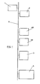
- FIG 1 the basic configuration can be seen of a preferred embodiment of the invention, in which main module (1), means of payment module (2), user interface module (3), a first extraction module (4A) (intended for control of a first type of extractors, for example, extractors of the screw type), a second extraction module (4B) (intended for control of a second type of extractors, for example, can extractors) and communications module (5) are connected to a CAN bus (6).
- the option has been chosen to have only one means of payment module (2) which can control several peripherals or means of payment units.
- two extraction modules (4A, 4B) have been incorporated, each designed for the control of a determined type of extractor, that is, with this system it is possible to control a vending machine with two different types of extractors.
- FIG. 2 illustrates how, in accordance with a preferred embodiment of the invention, means of payment module (2) is connected by means of cables to a coin return module (201), an MDB ICP coin mechanism (202), an MDB-ICP bank note reader (203) and a card reader (204).
- a coin return module 201
- an MDB ICP coin mechanism 202
- an MDB-ICP bank note reader 203
- a card reader 204
- an executive type coin mechanism (the same as an MDB-ICP bank card reader) has no obligation to inform the means of payment module of the exact amount of credit which they have.
- the main module (PRI) only has to use the credit information for displaying messages, never to perform any type of calculation since that task is carried out by the means of payment module.
- Figure 3 shows a block diagram in which it can be seen how the user interface module is associated with a monitor (301) (for example, an LCD screen of 16x2 characters, or an LED display with 8 characters), an indicator (LED) which indicates the out-of-change condition (302), an indicator (LED) which indicates the out-of-product condition (303), a button pad (304) in which each button is associated with a product, an alphanumeric keypad (305) (with this keypad it is necessary to press more than one key to make a selection and usually it is associated with screw extractors, for which reason it is also known as a screw keypad), 1 programming keypad (306) with 4 keys (A, B, C, D) which allow the operator to access and operate the machine configuration menu, 1 coin return button (307), an audible buzzer (308) (which emits beeps when the keys are pressed). Also, it can include a voice synthesizer (309) and one or several screens indicating price or product out of stock (311, 312 and 313) which are connected to user interface module
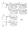
- FIG 4 it is observed how a first extraction module (4A) has been arranged to control a series of screw extractors (411-414; 421-424; 431-434; 441-444) through respective transistor cards (41; 42; 43; 44). Eight of the screw extractors (411-414; 421-424) correspond to a first tray of products and the others (431-434; 441-444) correspond to a second tray of products.
- the machine also includes extractors of another type, namely, can extractors (one of the types of can extractors employed by Azkoyen®) (451-453); these are controlled by a second extraction module (4B) through the corresponding transistor card (45).
- can extractors one of the types of can extractors employed by Azkoyen®
- the machine can include other types of extractors, in which case the extraction modules specifically designed to control said types of extractors are added preferably.
- a third extraction module (4C) is illustrated which controls, through transistor card 46, a plurality of extractors of carrousel type (461-463).
- each of the transistor cards (41) is illustrated schematically.
- the transistor cards (41-46) perform the interface function between the extractors and the corresponding extraction modules.
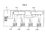
- Each extraction module (4A, 4B, 4C) has a series of connectors to which one or several transistor cards are connected, which in turn have four connectors (4101-4104) for connection of up to four extractors, it being possible to connect several transistor cards in series.
- To each connector (4101-4104) of the transistor card come the cables which power the extraction motor and the cables of the different micro-switches (end of travel, out of product, etc.) installed.
- the card also includes, either a transistor to regulate each of the motors with a single direction of rotation, or a transistor bridge for the motors which can turn in both directions, it being possible to have one of the arms of the bridge common to all extractors.
- the switching logic of the transistors resides in the microcontroller of the extraction module, which likewise has access to the values of the different micro-switches.
- transistor card (41) incorporates shift registers (4111, 4112) to act on the transistors and read the information of the micro-switches. With these registers the information in parallel form existing between transistor card (41) and extractor (411, 412, 413, 414) (the applied voltage on the different transistors or the voltage level of the micro-switches of the different extractors) is converted into serial communication between extraction module (4A) and transistor card (41), the information bits of the different extractors being sent sequentially.
Landscapes
- Physics & Mathematics (AREA)
- General Physics & Mathematics (AREA)
- Control Of Vending Devices And Auxiliary Devices For Vending Devices (AREA)
Applications Claiming Priority (2)
| Application Number | Priority Date | Filing Date | Title |
|---|---|---|---|
| ES200102822A ES2214083B1 (es) | 2001-12-18 | 2001-12-18 | Un sistema de control de una maquina expendedora. |
| ES200102822 | 2001-12-18 |
Publications (2)
| Publication Number | Publication Date |
|---|---|
| EP1321908A2 true EP1321908A2 (fr) | 2003-06-25 |
| EP1321908A3 EP1321908A3 (fr) | 2004-01-14 |
Family
ID=8499780
Family Applications (1)
| Application Number | Title | Priority Date | Filing Date |
|---|---|---|---|
| EP02380262A Withdrawn EP1321908A3 (fr) | 2001-12-18 | 2002-12-16 | Système de contrôle de machine de vente |
Country Status (2)
| Country | Link |
|---|---|
| EP (1) | EP1321908A3 (fr) |
| ES (1) | ES2214083B1 (fr) |
Cited By (3)
| Publication number | Priority date | Publication date | Assignee | Title |
|---|---|---|---|---|
| WO2007045099A1 (fr) * | 2005-10-20 | 2007-04-26 | Crane Canada Co. | Adaptateur de protocole de recycleur de billets de banque |
| US8190800B2 (en) * | 2007-07-06 | 2012-05-29 | Hitachi Ulsi Systems Co., Ltd. | Automatic vending machine with a plurality of modules and serial bus system |
| EP3092612A4 (fr) * | 2014-01-06 | 2017-05-31 | The Coca-Cola Company | Architecture de commande d'un distributeur |
Family Cites Families (7)
| Publication number | Priority date | Publication date | Assignee | Title |
|---|---|---|---|---|
| CH637228A5 (fr) * | 1980-03-27 | 1983-07-15 | Willemin Machines Sa | Dispositif de commande d'une machine ou d'une installation. |
| CA1216649A (fr) * | 1982-11-12 | 1987-01-13 | Misao Awane | Systeme de commande-regulation pour automate vendeur |
| GB2209079B (en) * | 1987-08-25 | 1991-06-26 | Sankey Vending Ltd | Apparatus for utilising processors |
| AU1260697A (en) * | 1996-02-21 | 1997-08-28 | Consolidated Technologies International | Multiplexed electrical system having a central controller and programmable control nodes |
| US6119053A (en) * | 1998-03-27 | 2000-09-12 | The Coca-Cola Company | Vending machine dual bus architecture |
| JP2000271268A (ja) * | 1999-03-23 | 2000-10-03 | Aruze Corp | 遊技機 |
| JP2001319267A (ja) * | 2000-05-09 | 2001-11-16 | Sanden Corp | 自動販売機の制御システム |
-
2001
- 2001-12-18 ES ES200102822A patent/ES2214083B1/es not_active Expired - Fee Related
-
2002
- 2002-12-16 EP EP02380262A patent/EP1321908A3/fr not_active Withdrawn
Cited By (6)
| Publication number | Priority date | Publication date | Assignee | Title |
|---|---|---|---|---|
| WO2007045099A1 (fr) * | 2005-10-20 | 2007-04-26 | Crane Canada Co. | Adaptateur de protocole de recycleur de billets de banque |
| CN101341519B (zh) * | 2005-10-20 | 2010-12-29 | 天鹤加拿大公司 | 钞票再循环器协议适配器 |
| US8190800B2 (en) * | 2007-07-06 | 2012-05-29 | Hitachi Ulsi Systems Co., Ltd. | Automatic vending machine with a plurality of modules and serial bus system |
| EP3092612A4 (fr) * | 2014-01-06 | 2017-05-31 | The Coca-Cola Company | Architecture de commande d'un distributeur |
| US10358334B2 (en) | 2014-01-06 | 2019-07-23 | The Coca-Cola Company | Dispenser control architecture |
| US11084704B2 (en) | 2014-01-06 | 2021-08-10 | The Coca-Cola Company | Dispenser control architecture |
Also Published As
| Publication number | Publication date |
|---|---|
| EP1321908A3 (fr) | 2004-01-14 |
| ES2214083A1 (es) | 2004-09-01 |
| ES2214083B1 (es) | 2005-11-01 |
Similar Documents
| Publication | Publication Date | Title |
|---|---|---|
| US7490762B2 (en) | Card activated cash dispensing automated transaction machine system and method | |
| EP0014312B1 (fr) | Terminal périphérique et système d'exécution des transactions utilisant un tel terminal | |
| US7110954B2 (en) | Wireless purchase and on-line inventory apparatus and method for vending machines | |
| US20070227856A1 (en) | Payment system for a vending machine | |
| EP0645744A2 (fr) | Système à libre accès disposant de capacités de prévision | |
| EP0722904A1 (fr) | Dispositif de distribution de carburants | |
| US20120179602A1 (en) | Automated Kiosk Transaction Function and Monitoring System | |
| EP1324286A2 (fr) | Distributeur automatique | |
| WO2001004851A1 (fr) | Appareil ameliore pour effectuer des transactions de paiements a distance | |
| US6064991A (en) | Interchangeable postage calculating module and method for data transmission | |
| JPH11353425A (ja) | Icカード端末装置 | |
| EP1321908A2 (fr) | Système de contrôle de machine de vente | |
| CA2406257C (fr) | Systeme et procede pour machine transactionnelle automatique | |
| EP1100059B1 (fr) | Systèmes de transfert de valeurs | |
| EP0832473B1 (fr) | Dispositif d'echange d'informations entre une caisse enregistreuse et un dispositif de traitement de paiement | |
| EP1043699A1 (fr) | Validation de la monnaie | |
| EP1347372B1 (fr) | Méthode et dispositif d'impression et de préparation de plis postaux à partir d'un flux de données | |
| CN111373427B (zh) | 自动售货机的mdb数据处理方法及系统 | |
| EP0499008B1 (fr) | Terminal d'entretien pour validation et identification d'unité | |
| CN1885356A (zh) | 自动售货机 | |
| EP0874334A1 (fr) | Module d'application sécurisé pour applications multi-services et un terminal muni d'un tel module d'application sécurisé | |
| JPS5844425Y2 (ja) | 入出力装置 | |
| JPS58222372A (ja) | 金銭出納装置 | |
| AU694298B2 (en) | Fuel dispenser | |
| KR100250876B1 (ko) | 금전 등록기의 프로그램 변경 내역 관리 방법 |
Legal Events
| Date | Code | Title | Description |
|---|---|---|---|
| PUAI | Public reference made under article 153(3) epc to a published international application that has entered the european phase |
Free format text: ORIGINAL CODE: 0009012 |
|
| AK | Designated contracting states |
Designated state(s): AT BE BG CH CY CZ DE DK EE ES FI FR GB GR IE IT LI LU MC NL PT SE SI SK TR |
|
| AX | Request for extension of the european patent |
Extension state: AL LT LV MK RO |
|
| PUAL | Search report despatched |
Free format text: ORIGINAL CODE: 0009013 |
|
| AK | Designated contracting states |
Kind code of ref document: A3 Designated state(s): AT BE BG CH CY CZ DE DK EE ES FI FR GB GR IE IT LI LU MC NL PT SE SI SK TR |
|
| AX | Request for extension of the european patent |
Extension state: AL LT LV MK RO |
|
| 17P | Request for examination filed |
Effective date: 20040713 |
|
| AKX | Designation fees paid |
Designated state(s): AT BE BG CH CY CZ DE DK EE ES FI FR GB GR IE IT LI LU MC NL PT SE SI SK TR |
|
| 17Q | First examination report despatched |
Effective date: 20041123 |
|
| STAA | Information on the status of an ep patent application or granted ep patent |
Free format text: STATUS: THE APPLICATION IS DEEMED TO BE WITHDRAWN |
|
| 18D | Application deemed to be withdrawn |
Effective date: 20050604 |