EP1321241A1 - Pressure gas cartridge for fastening apparatus and adaptor for intermediate joint - Google Patents
Pressure gas cartridge for fastening apparatus and adaptor for intermediate joint Download PDFInfo
- Publication number
- EP1321241A1 EP1321241A1 EP02292941A EP02292941A EP1321241A1 EP 1321241 A1 EP1321241 A1 EP 1321241A1 EP 02292941 A EP02292941 A EP 02292941A EP 02292941 A EP02292941 A EP 02292941A EP 1321241 A1 EP1321241 A1 EP 1321241A1
- Authority
- EP
- European Patent Office
- Prior art keywords
- valve
- cartridge
- ejection
- seal
- gas
- Prior art date
- Legal status (The legal status is an assumption and is not a legal conclusion. Google has not performed a legal analysis and makes no representation as to the accuracy of the status listed.)
- Granted
Links
Images

Classifications
-
- F—MECHANICAL ENGINEERING; LIGHTING; HEATING; WEAPONS; BLASTING
- F16—ENGINEERING ELEMENTS AND UNITS; GENERAL MEASURES FOR PRODUCING AND MAINTAINING EFFECTIVE FUNCTIONING OF MACHINES OR INSTALLATIONS; THERMAL INSULATION IN GENERAL
- F16K—VALVES; TAPS; COCKS; ACTUATING-FLOATS; DEVICES FOR VENTING OR AERATING
- F16K1/00—Lift valves or globe valves, i.e. cut-off apparatus with closure members having at least a component of their opening and closing motion perpendicular to the closing faces
- F16K1/30—Lift valves or globe valves, i.e. cut-off apparatus with closure members having at least a component of their opening and closing motion perpendicular to the closing faces specially adapted for pressure containers
- F16K1/301—Lift valves or globe valves, i.e. cut-off apparatus with closure members having at least a component of their opening and closing motion perpendicular to the closing faces specially adapted for pressure containers only shut-off valves, i.e. valves without additional means
- F16K1/303—Lift valves or globe valves, i.e. cut-off apparatus with closure members having at least a component of their opening and closing motion perpendicular to the closing faces specially adapted for pressure containers only shut-off valves, i.e. valves without additional means with a valve member, e.g. stem or shaft, passing through the seat
-
- B—PERFORMING OPERATIONS; TRANSPORTING
- B25—HAND TOOLS; PORTABLE POWER-DRIVEN TOOLS; MANIPULATORS
- B25C—HAND-HELD NAILING OR STAPLING TOOLS; MANUALLY OPERATED PORTABLE STAPLING TOOLS
- B25C1/00—Hand-held nailing tools; Nail feeding devices
- B25C1/08—Hand-held nailing tools; Nail feeding devices operated by combustion pressure
-
- F—MECHANICAL ENGINEERING; LIGHTING; HEATING; WEAPONS; BLASTING
- F16—ENGINEERING ELEMENTS AND UNITS; GENERAL MEASURES FOR PRODUCING AND MAINTAINING EFFECTIVE FUNCTIONING OF MACHINES OR INSTALLATIONS; THERMAL INSULATION IN GENERAL
- F16K—VALVES; TAPS; COCKS; ACTUATING-FLOATS; DEVICES FOR VENTING OR AERATING
- F16K1/00—Lift valves or globe valves, i.e. cut-off apparatus with closure members having at least a component of their opening and closing motion perpendicular to the closing faces
- F16K1/30—Lift valves or globe valves, i.e. cut-off apparatus with closure members having at least a component of their opening and closing motion perpendicular to the closing faces specially adapted for pressure containers
- F16K1/308—Connecting means
-
- F—MECHANICAL ENGINEERING; LIGHTING; HEATING; WEAPONS; BLASTING
- F16—ENGINEERING ELEMENTS AND UNITS; GENERAL MEASURES FOR PRODUCING AND MAINTAINING EFFECTIVE FUNCTIONING OF MACHINES OR INSTALLATIONS; THERMAL INSULATION IN GENERAL
- F16L—PIPES; JOINTS OR FITTINGS FOR PIPES; SUPPORTS FOR PIPES, CABLES OR PROTECTIVE TUBING; MEANS FOR THERMAL INSULATION IN GENERAL
- F16L29/00—Joints with fluid cut-off means
- F16L29/02—Joints with fluid cut-off means with a cut-off device in one of the two pipe ends, the cut-off device being automatically opened when the coupling is applied
-
- F—MECHANICAL ENGINEERING; LIGHTING; HEATING; WEAPONS; BLASTING
- F17—STORING OR DISTRIBUTING GASES OR LIQUIDS
- F17C—VESSELS FOR CONTAINING OR STORING COMPRESSED, LIQUEFIED OR SOLIDIFIED GASES; FIXED-CAPACITY GAS-HOLDERS; FILLING VESSELS WITH, OR DISCHARGING FROM VESSELS, COMPRESSED, LIQUEFIED, OR SOLIDIFIED GASES
- F17C13/00—Details of vessels or of the filling or discharging of vessels
- F17C13/04—Arrangement or mounting of valves
-
- F—MECHANICAL ENGINEERING; LIGHTING; HEATING; WEAPONS; BLASTING
- F17—STORING OR DISTRIBUTING GASES OR LIQUIDS
- F17C—VESSELS FOR CONTAINING OR STORING COMPRESSED, LIQUEFIED OR SOLIDIFIED GASES; FIXED-CAPACITY GAS-HOLDERS; FILLING VESSELS WITH, OR DISCHARGING FROM VESSELS, COMPRESSED, LIQUEFIED, OR SOLIDIFIED GASES
- F17C2201/00—Vessel construction, in particular geometry, arrangement or size
- F17C2201/01—Shape
- F17C2201/0104—Shape cylindrical
- F17C2201/0119—Shape cylindrical with flat end-piece
-
- F—MECHANICAL ENGINEERING; LIGHTING; HEATING; WEAPONS; BLASTING
- F17—STORING OR DISTRIBUTING GASES OR LIQUIDS
- F17C—VESSELS FOR CONTAINING OR STORING COMPRESSED, LIQUEFIED OR SOLIDIFIED GASES; FIXED-CAPACITY GAS-HOLDERS; FILLING VESSELS WITH, OR DISCHARGING FROM VESSELS, COMPRESSED, LIQUEFIED, OR SOLIDIFIED GASES
- F17C2201/00—Vessel construction, in particular geometry, arrangement or size
- F17C2201/03—Orientation
- F17C2201/032—Orientation with substantially vertical main axis
-
- F—MECHANICAL ENGINEERING; LIGHTING; HEATING; WEAPONS; BLASTING
- F17—STORING OR DISTRIBUTING GASES OR LIQUIDS
- F17C—VESSELS FOR CONTAINING OR STORING COMPRESSED, LIQUEFIED OR SOLIDIFIED GASES; FIXED-CAPACITY GAS-HOLDERS; FILLING VESSELS WITH, OR DISCHARGING FROM VESSELS, COMPRESSED, LIQUEFIED, OR SOLIDIFIED GASES
- F17C2201/00—Vessel construction, in particular geometry, arrangement or size
- F17C2201/05—Size
- F17C2201/058—Size portable (<30 l)
-
- F—MECHANICAL ENGINEERING; LIGHTING; HEATING; WEAPONS; BLASTING
- F17—STORING OR DISTRIBUTING GASES OR LIQUIDS
- F17C—VESSELS FOR CONTAINING OR STORING COMPRESSED, LIQUEFIED OR SOLIDIFIED GASES; FIXED-CAPACITY GAS-HOLDERS; FILLING VESSELS WITH, OR DISCHARGING FROM VESSELS, COMPRESSED, LIQUEFIED, OR SOLIDIFIED GASES
- F17C2205/00—Vessel construction, in particular mounting arrangements, attachments or identifications means
- F17C2205/03—Fluid connections, filters, valves, closure means or other attachments
- F17C2205/0302—Fittings, valves, filters, or components in connection with the gas storage device
- F17C2205/0308—Protective caps
-
- F—MECHANICAL ENGINEERING; LIGHTING; HEATING; WEAPONS; BLASTING
- F17—STORING OR DISTRIBUTING GASES OR LIQUIDS
- F17C—VESSELS FOR CONTAINING OR STORING COMPRESSED, LIQUEFIED OR SOLIDIFIED GASES; FIXED-CAPACITY GAS-HOLDERS; FILLING VESSELS WITH, OR DISCHARGING FROM VESSELS, COMPRESSED, LIQUEFIED, OR SOLIDIFIED GASES
- F17C2205/00—Vessel construction, in particular mounting arrangements, attachments or identifications means
- F17C2205/03—Fluid connections, filters, valves, closure means or other attachments
- F17C2205/0302—Fittings, valves, filters, or components in connection with the gas storage device
- F17C2205/0323—Valves
- F17C2205/0326—Valves electrically actuated
-
- F—MECHANICAL ENGINEERING; LIGHTING; HEATING; WEAPONS; BLASTING
- F17—STORING OR DISTRIBUTING GASES OR LIQUIDS
- F17C—VESSELS FOR CONTAINING OR STORING COMPRESSED, LIQUEFIED OR SOLIDIFIED GASES; FIXED-CAPACITY GAS-HOLDERS; FILLING VESSELS WITH, OR DISCHARGING FROM VESSELS, COMPRESSED, LIQUEFIED, OR SOLIDIFIED GASES
- F17C2205/00—Vessel construction, in particular mounting arrangements, attachments or identifications means
- F17C2205/03—Fluid connections, filters, valves, closure means or other attachments
- F17C2205/0302—Fittings, valves, filters, or components in connection with the gas storage device
- F17C2205/0323—Valves
- F17C2205/0329—Valves manually actuated
-
- F—MECHANICAL ENGINEERING; LIGHTING; HEATING; WEAPONS; BLASTING
- F17—STORING OR DISTRIBUTING GASES OR LIQUIDS
- F17C—VESSELS FOR CONTAINING OR STORING COMPRESSED, LIQUEFIED OR SOLIDIFIED GASES; FIXED-CAPACITY GAS-HOLDERS; FILLING VESSELS WITH, OR DISCHARGING FROM VESSELS, COMPRESSED, LIQUEFIED, OR SOLIDIFIED GASES
- F17C2205/00—Vessel construction, in particular mounting arrangements, attachments or identifications means
- F17C2205/03—Fluid connections, filters, valves, closure means or other attachments
- F17C2205/0302—Fittings, valves, filters, or components in connection with the gas storage device
- F17C2205/037—Quick connecting means, e.g. couplings
- F17C2205/0373—Adapters
-
- F—MECHANICAL ENGINEERING; LIGHTING; HEATING; WEAPONS; BLASTING
- F17—STORING OR DISTRIBUTING GASES OR LIQUIDS
- F17C—VESSELS FOR CONTAINING OR STORING COMPRESSED, LIQUEFIED OR SOLIDIFIED GASES; FIXED-CAPACITY GAS-HOLDERS; FILLING VESSELS WITH, OR DISCHARGING FROM VESSELS, COMPRESSED, LIQUEFIED, OR SOLIDIFIED GASES
- F17C2223/00—Handled fluid before transfer, i.e. state of fluid when stored in the vessel or before transfer from the vessel
- F17C2223/01—Handled fluid before transfer, i.e. state of fluid when stored in the vessel or before transfer from the vessel characterised by the phase
- F17C2223/0107—Single phase
- F17C2223/0123—Single phase gaseous, e.g. CNG, GNC
-
- F—MECHANICAL ENGINEERING; LIGHTING; HEATING; WEAPONS; BLASTING
- F17—STORING OR DISTRIBUTING GASES OR LIQUIDS
- F17C—VESSELS FOR CONTAINING OR STORING COMPRESSED, LIQUEFIED OR SOLIDIFIED GASES; FIXED-CAPACITY GAS-HOLDERS; FILLING VESSELS WITH, OR DISCHARGING FROM VESSELS, COMPRESSED, LIQUEFIED, OR SOLIDIFIED GASES
- F17C2223/00—Handled fluid before transfer, i.e. state of fluid when stored in the vessel or before transfer from the vessel
- F17C2223/03—Handled fluid before transfer, i.e. state of fluid when stored in the vessel or before transfer from the vessel characterised by the pressure level
- F17C2223/035—High pressure (>10 bar)
-
- F—MECHANICAL ENGINEERING; LIGHTING; HEATING; WEAPONS; BLASTING
- F17—STORING OR DISTRIBUTING GASES OR LIQUIDS
- F17C—VESSELS FOR CONTAINING OR STORING COMPRESSED, LIQUEFIED OR SOLIDIFIED GASES; FIXED-CAPACITY GAS-HOLDERS; FILLING VESSELS WITH, OR DISCHARGING FROM VESSELS, COMPRESSED, LIQUEFIED, OR SOLIDIFIED GASES
- F17C2270/00—Applications
- F17C2270/05—Applications for industrial use
- F17C2270/0545—Tools
-
- Y—GENERAL TAGGING OF NEW TECHNOLOGICAL DEVELOPMENTS; GENERAL TAGGING OF CROSS-SECTIONAL TECHNOLOGIES SPANNING OVER SEVERAL SECTIONS OF THE IPC; TECHNICAL SUBJECTS COVERED BY FORMER USPC CROSS-REFERENCE ART COLLECTIONS [XRACs] AND DIGESTS
- Y10—TECHNICAL SUBJECTS COVERED BY FORMER USPC
- Y10T—TECHNICAL SUBJECTS COVERED BY FORMER US CLASSIFICATION
- Y10T137/00—Fluid handling
- Y10T137/8593—Systems
- Y10T137/87917—Flow path with serial valves and/or closures
- Y10T137/88022—One valve head provides seat for other head
- Y10T137/8803—Also carries head of other valve
Definitions
- the invention relates first of all to a compressed gas cartridge intended to supply gas to a compressed gas fixing device, that is to say a device for fixing fasteners of the nail type, comprising a intake device.
- a compressed gas fixing device that is to say a device for fixing fasteners of the nail type, comprising a intake device.
- the device's intake device is usually a solenoid valve.
- Known intake devices such as that described in FR 2 771 796, have a male intake nozzle, inside a bowl formed by a peripheral protective skirt. This tip Intake is intended to cooperate with a cartridge ejection valve to move the valve away from its seat and thus allow the transfer of gas from the cartridge into the device's intake device. During the operation of transfer, it is necessary to seal around the cartridge valve and the inlet nozzle of the appliance. To this end, often, and especially in in the case of the cartridge described in FR 2 771 796, the ejection valve of the cartridge extends into a male end piece which cooperates with the male end piece inlet of the device inside a fitting so arranged appropriate.
- the present invention aims to eliminate these drawbacks.
- a compressed gas cartridge intended for supply gas to a compressed gas fixing device, comprising a protective edge forming a bowl inside which a valve ejection having a bearing and displacement surface is mounted movable in translation between a rest position and an ejection position gas, characterized in that the ejection valve is mounted, at the inside of a seal, set back from the edge of the bowl and the valve support surface does not protrude from the edge of the bowl in the rest position and is set back from the surface facing the outside of the gasket in the gas ejection position.
- the valve in rest position, protrudes from the seal.
- the bearing surface of the valve is intended to cooperate directly with a male end of a gas intake device the device to push the valve back into the ejection position in which the gasket extends on either side of the joint plane of the valve and of the male end of the intake device.
- the seal comprises an external sleeve and a internal cord in an annular shoulder of an enlarged portion of the muff.
- the bearing surface of the valve, in the rest position is set back relative to the turned surface outward of the seal to receive a first portion male end of an intermediate joint including a second portion female end is intended to receive a male end of a device gas inlet from the fixing device to push back the valve in dejection position.
- the invention also relates to the adaptation cap for the second embodiment of the cartridge of the invention, arranged to be received in the protective bowl of the cartridge and protrude therefrom and in which is mounted the intermediate seal with male end portion of cooperation with the ejection valve and female end portion of receiving the male connector from the gas inlet device of the fixation.
- a compressed gas cartridge 1 is mounted on solenoid valve 2 for compressed gas intake of a drive unit nail-like fasteners, via a connector sealing 3.
- the inlet solenoid valve 2 has a male inlet nozzle 4 extending axially - along the axis 8 - projecting from the bottom 5 of a bowl 6, formed by an annular skirt 7 for receiving an ejection foot 14 of the cartridge 1.
- the end 9 of the inlet nozzle 4 of the solenoid valve is set back relative to the annular edge 10 of the skirt 7.
- the compressed gas cartridge 1 comprises a cylindrical envelope 11 ending with a thick annular bead 12 forming a bowl 13 in the center from which the ejection foot 14 protrudes.
- the foot 14 does not protrude outside the plane of the annular edge 15 of the bead 12. In the example considered, it is flush with it.
- An ejection valve 16 is mounted in the ejection foot 14, sliding in a sleeve-shaped seal 20 against the action of a return spring 17.
- the valve 16 has, projecting from the seal 20, but not outside the bowl 13, an external part 18 extended by an internal part 19 having an annular sealing rim 21.
- the return spring 17 is housed inside the seal sleeve 20, around the internal part of valve 19, in abutment against the annular sealing rim 21 of the part of valve 19, of diameter substantially equal to that of the central bore 22 of the sleeve 20 but very slightly lower, for the exhaust compressed gas between the wall of the bore 22 of the sleeve 20 and this flange 21.
- the flange 21 of the valve 16 is in abutment against a bead sealing ring 23 housed in an annular shoulder of a portion enlarged 24 of the sealing sleeve 20 of the seal 3.
- the seal 3 therefore comprises a sleeve 20 and a cord 23 housed in the foot 14 of which an annular edge 25 covers the enlarged portion 24 of the sleeve and the sealing bead 23.
- the edge 25 of the foot 14 here is flush with the plane of the edge 15 of the bead 12.
- the sealing sleeve 20 is thus slightly set back from the edge plane 15.
- the valve part external 18 has, facing outward, a surface 26 of support and displacement of the valve which, in all circumstances, does not protrude out of the edge plane 15. Here, it is flush with it.
- its external part 18, by its portion adjacent to the surface support 26, protrudes from the sealing bead 23.
- the diameter of the outer valve portion 18 is substantially the same, very slightly smaller, than the diameter of the passage opening 27 of the sealing bead 23 and the same as the outside diameter of the intake nozzle 4.
- the side wall 28 of the external valve part 18 and the outer side wall 29 of the inlet nozzle 4 are successively in contact with the wall of the passage orifice 27 of the sealing bead 23. They constitute cylindrical surfaces sealing, axis 8.
- the end 9 of the endpiece 4 bears against the face 26 of the external valve part 18, arranged perpendicular to axis 8.
- the external valve part 18, in operation is pushed back in the ejection position by the intake nozzle 4 against the action of the spring return 17, to clear the edge of the annular valve 21 of the cord seal 23 and let the gas escape from the cartridge 1 in the solenoid valve 2 of the fixing device.
- the surface support and displacement 26 of the valve 18, 19 is set back relative to the surface 30 facing outwards from the joint bead 23, and even by with respect to its surface 31 facing inwards.
- the seal 3 In the ejection position, the seal 3, with its sleeve 20 and its bead 23 extends on either side of the joint plane of the valve 18, 19 and of the male inlet nozzle 4, which is the plane of the bearing surface 26 of the outer valve part 18.
- an intermediate seal 40 is used mounted in a adapter cap 50.
- the intermediate seal 40 is a sleeve, with a first portion male end 41, mounted in abutment against the bearing surface 26 of the valve 16 to actuate it and move aside its sealing edge 21 of the cord sealing 23, and a second female end portion 42, intended for receive the male inlet nozzle 4 of the solenoid valve 2.
- the diameter outside of the actuating end 41 corresponds to that of the end piece male inlet 4.
- the bore 43 for the passage of compressed gas, extending in the intermediate seal 40, is stepped and its section, in the portion end 42, is significantly larger than at the other end 41 for be of a diameter equal to the outside diameter of the intake nozzle 4. In consequently, the outside diameter of the end portion 42 is also enlarged relative to that of the end portion 41.
- the wall of the enlarged bore 44 in the end portion 42 has a lip sealing ring 45.
- the adapter cap 50 has the shape of a ring with a through bore stepped 51, 52, of section (51) of a diameter substantially equal to the diameter outside of the enlarged female end portion 42 of the intermediate seal 40, in a male end portion 53 intended to be received in the bowl 6 of the solenoid valve 2, and of enlarged section (52) with a diameter substantially equal to the outside diameter of the ejection foot 14 ', in a second female end portion 54 intended to receive this foot ejecting 14 'from the cartridge 1'.
- the bore 51, 52 of the cap 50 extends over a length substantially equal to that of the intermediate seal 40.
- the cap 50 At its end of smaller section 53, the cap 50 has a rim annular 55 for retaining the intermediate seal 40.
- the outer wall 56 of the cover 50 is also stepped, adapted to the bore 51, 52 for receiving the intermediate seal as well as the skirt 7 of the solenoid valve 2 and it ends, at its widened end 54, by an annular edge 57 of outside diameter equal to the inside diameter of the bead 12 of the cartridge 1 'to be received in the bowl 13 of the cartridge 1 '.
Abstract
Description
L'invention concerne tout d'abord une cartouche de gaz comprimé destinée à alimenter en gaz un appareil de fixation à gaz comprimé, c'est-à-dire un appareil d'entrainement d'éléments de fixation du type clou, comportant un dispositif d'admission. Le dispositif d'admission de l'appareil est généralement une électrovanne.The invention relates first of all to a compressed gas cartridge intended to supply gas to a compressed gas fixing device, that is to say a device for fixing fasteners of the nail type, comprising a intake device. The device's intake device is usually a solenoid valve.
Les dispositifs d'admission connus, comme par exemple celui décrit dans
FR 2 771 796, comportent un embout d'admission mâle, à l'intérieur d'une
cuvette formée par une jupe périphérique de protection. Cet embout
d'admission est destiné à coopérer avec un clapet d'éjection de la cartouche
pour écarter le clapet de son siège et permettre ainsi le transfert de gaz de la
cartouche dans le dispositif d'admission de l'appareil. Lors de l'opération de
transfert, il faut assurer l'étanchéité autour du clapet de la cartouche et de
l'embout d'admission de l'appareil. A cet effet, souvent, et notamment dans
le cas de la cartouche décrite dans FR 2 771 796, le clapet d'éjection de la
cartouche se prolonge en un embout mâle qui coopère avec l'embout mâle
d'admission de l'appareil à l'intérieur d'un raccord agencé de façon
appropriée.Known intake devices, such as that described in
Une telle disposition présente toutefois l'inconvénient que l'embout de clapet d'éjection de la cartouche fait saillie hors du bord d'une coupelle de protection, avec le risque qu'il soit cassé au cours de sa manutention, sans parler des contraintes de stockage.However, such an arrangement has the disadvantage that the end piece cartridge ejection valve protrudes from the edge of a cup protection, with the risk that it will be broken during handling, without talk about storage constraints.
La présente invention vise à éliminer ces inconvénients.The present invention aims to eliminate these drawbacks.
A cet effet, elle concerne une cartouche de gaz comprimé destinée à alimenter en gaz un appareil de fixation à gaz comprimé, comportant un bord de protection formant cuvette à l'intérieur de laquelle un clapet d'éjection présentant une surface d'appui et de déplacement est monté mobile en translation entre une position de repos et une position d'éjection de gaz, caractérisée par le fait que le clapet d'éjection est monté, à l'intérieur d'un joint d'étanchéité, en retrait par rapport au bord de la cuvette et la surface d'appui du clapet ne fait pas saillie hors du bord de la cuvette en position de repos et est en retrait par rapport à la surface tournée vers l'extérieur du joint d'étanchéité en position d'éjection de gaz.To this end, it relates to a compressed gas cartridge intended for supply gas to a compressed gas fixing device, comprising a protective edge forming a bowl inside which a valve ejection having a bearing and displacement surface is mounted movable in translation between a rest position and an ejection position gas, characterized in that the ejection valve is mounted, at the inside of a seal, set back from the edge of the bowl and the valve support surface does not protrude from the edge of the bowl in the rest position and is set back from the surface facing the outside of the gasket in the gas ejection position.
En toutes circonstances, le clapet d'éjection de la cartouche de l'invention ne fait donc plus saillie hors de la cuvette de protection. In all circumstances, the cartridge ejection valve of the invention no longer protrudes out of the protective bowl.
Dans une première forme de réalisation de la cartouche, le clapet, en position de repos, fait saillie hors du joint d'étanchéité.In a first embodiment of the cartridge, the valve, in rest position, protrudes from the seal.
Dans ce cas, la surface d'appui du clapet est destinée à coopérer directement avec un embout mâle d'un dispositif d'admission de gaz de l'appareil pour repousser le clapet en position d'éjection dans laquelle le joint d'étanchéité s'étend de part et d'autre du plan de joint du clapet et de l'embout mâle du dispositif d'admission.In this case, the bearing surface of the valve is intended to cooperate directly with a male end of a gas intake device the device to push the valve back into the ejection position in which the gasket extends on either side of the joint plane of the valve and of the male end of the intake device.
Avantageusement, le joint d'étanchéité comporte un manchon externe et un cordon interne dans un épaulement annulaire d'une portion élargie du manchon.Advantageously, the seal comprises an external sleeve and a internal cord in an annular shoulder of an enlarged portion of the muff.
Dans une deuxième forme de réalisation de la cartouche, la surface d'appui du clapet, en position de repos, est en retrait par rapport à la surface tournée vers l'extérieur du joint d'étanchéité pour recevoir une première portion d'extrémité mâle d'un joint intermédiaire dont une deuxième portion d'extrémité femelle est destinée à recevoir un embout mâle d'un dispositif d'admission de gaz de l'appareil de fixation pour repousser le clapet en position déjection.In a second embodiment of the cartridge, the bearing surface of the valve, in the rest position, is set back relative to the turned surface outward of the seal to receive a first portion male end of an intermediate joint including a second portion female end is intended to receive a male end of a device gas inlet from the fixing device to push back the valve in dejection position.
L'invention concerne également la coiffe d'adaptation pour la deuxième forme de réalisation de la cartouche de l'invention, agencée pour être reçue dans la cuvette de protection de la cartouche et en faire saillie et dans laquelle est monté le joint intermédiaire à portion d'extrémité mâle de coopération avec le clapet d'éjection et portion d'extrémité femelle de réception de l'embout mâle du dispositif d'admission de gaz de l'appareil de fixation.The invention also relates to the adaptation cap for the second embodiment of the cartridge of the invention, arranged to be received in the protective bowl of the cartridge and protrude therefrom and in which is mounted the intermediate seal with male end portion of cooperation with the ejection valve and female end portion of receiving the male connector from the gas inlet device of the fixation.
L'invention sera mieux comprise à l'aide de la description de deux formes de réalisation de la cartouche, en référence au dessin annexé, sur lequel
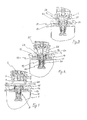
- la figure 1 est une vue en coupe éclatée de la première forme de réalisation de la cartouche de gaz comprimé de l'invention et d'une électrovanne d'admission de gaz d'un appareil de fixation à gaz comprimé;
- la figure 2 est une vue en coupe de la cartouche et de l'électrovanne de la figure 1 avec le clapet d'éjection et l'embout d'admission en contact l'un avec l'autre;
- la figure 3 est une vue analogue à celle de la figure 2, mais à l'état de transfert de gaz de la cartouche dans l'appareil;
- la figure 4 est une vue d'ensemble de l'électrovanne de la figure 1 montée sur la cartouche ;
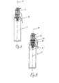
- la figure 5 est une vue en coupe éclatée de la deuxième forme de réalisation de la cartouche de gaz comprimé de l'invention, d'une électrovanne d'admission de gaz d'un appareil de fixation à gaz comprimé et de la coiffe d'adaptation avec son joint intermédiaire;
- la figure 6 est une vue en coupe de la cartouche et de l'électrovanne de la figure 5 avec le clapet d'éjection et le joint intermédiaire en contact l'un avec l'autre;
- la figure 7 une vue analogue à celle de la figure 6, mais à l'état de transfert de gaz de la cartouche dans l'appareil;
- la figure 8 est une vue d'ensemble de l'électrovanne de la figure 5 montée sur la cartouche ;
- Figure 1 is an exploded sectional view of the first embodiment of the compressed gas cartridge of the invention and of a gas inlet solenoid valve of a compressed gas fixing apparatus;
- Figure 2 is a sectional view of the cartridge and the solenoid valve of Figure 1 with the ejection valve and the intake nozzle in contact with each other;
- Figure 3 is a view similar to that of Figure 2, but in the state of gas transfer from the cartridge into the apparatus;
- Figure 4 is an overview of the solenoid valve of Figure 1 mounted on the cartridge;
- Figure 5 is an exploded sectional view of the second embodiment of the compressed gas cartridge of the invention, of a gas inlet solenoid valve of a compressed gas fixing device and of the cap adaptation with its intermediate seal;
- Figure 6 is a sectional view of the cartridge and the solenoid valve of Figure 5 with the ejection valve and the intermediate seal in contact with each other;
- Figure 7 a view similar to that of Figure 6, but in the state of gas transfer from the cartridge into the device;
- Figure 8 is an overall view of the solenoid valve of Figure 5 mounted on the cartridge;
En référence à la figure 4, une cartouche de gaz comprimé 1 se monte sur
l'électrovanne 2 d'admission de gaz comprimé d'un appareil d'entrainement
d'éléments de fixation du genre clou, par l'intermédiaire d'un raccord
d'étanchéité 3.Referring to Figure 4, a compressed
L'électrovanne d'admission 2 comporte un embout d'admission mâle 4
s'étendant axialement - le long de l'axe 8 - en saillie hors du fond 5 d'une
cuvette 6, formée par une jupe annulaire 7 de réception d'un pied d'éjection
14 de la cartouche 1. L'extrémité 9 de l'embout d'admission 4 de
l'électrovanne est en retrait par rapport au bord annulaire 10 de la jupe 7.The
La cartouche de gaz comprimé 1 comporte une enveloppe cylindrique 11 se
terminant par un épais bourrelet annulaire 12 formant cuvette 13 au centre
de laquelle fait saillie le pied d'éjection 14. Le pied 14 ne fait pas saillie
hors du plan du bord annulaire 15 du bourrelet 12. Dans l'exemple
considéré, il l'affleure.The
Un clapet d'éjection 16 est monté dans le pied d'éjection 14, coulissant dans
un joint 20 en forme de manchon contre l'action d'un ressort de rappel 17.
Le clapet 16 comporte, en saillie hors du joint 20, mais pas hors de la
cuvette 13, une partie externe 18 prolongée par une partie interne 19
comportant un rebord annulaire d'étanchéité 21. Le ressort de rappel 17 est
logé à l'intérieur du manchon de joint 20, autour de la partie interne de
clapet 19, en appui contre le rebord annulaire d'étanchéité 21 de la partie de
clapet 19, de diamètre sensiblement égal à celui de l'alésage central 22 du
manchon 20 mais toutefois très légèrement inférieur, pour l'échappement
du gaz comprimé entre la paroi de l'alésage 22 du manchon 20 et ce rebord
21. Au repos, le rebord 21 du clapet 16 est en appui contre un cordon
annulaire d'étanchéité 23 logé dans un épaulement annulaire d'une portion
élargie 24 du manchon d'étanchéité 20 du joint 3.An
Le joint d'étanchéité 3 comporte donc un manchon 20 et un cordon 23 logés
dans le pied 14 dont un bord annulaire 25 recouvre la portion élargie 24 du
manchon et le cordon d'étanchéité 23. Le bord 25 du pied 14 affleure ici le
plan du bord 15 du bourrelet 12. Le manchon d'étanchéité 20 est ainsi
légèrement en retrait par rapport au plan du bord 15. La partie de clapet
externe 18 présente, tournée vers l'extérieur, une surface 26 d'appui et de
déplacement du clapet qui, en toutes circonstances, ne fait pas saillie hors
du plan du bord 15. Ici, elle l'affleure. Par contre, dans la position de repos
du clapet 16, sa partie externe 18, par sa portion adjacente à la surface
d'appui 26, fait saillie hors du cordon d'étanchéité 23.The
On notera que le diamètre de la partie de clapet externe 18 est sensiblement
le même, très légèrement inférieur, que le diamètre de l'orifice de passage
27 du cordon d'étanchéité 23 et le même que le diamètre extérieur de
l'embout d'admission 4.Note that the diameter of the
En fonctionnement, la paroi latérale 28 de la partie de clapet externe 18 et
la paroi latérale extérieure 29 de l'embout d'admission 4 sont
successivement en contact avec la paroi de l'orifice de passage 27 du
cordon d'étanchéité 23. Elles constituent des surfaces cylindriques
d'étanchéité, d'axe 8.In operation, the side wall 28 of the
Plus précisément, et toujours en fonctionnement, l'extrémité 9 de l'embout
4 vient en appui contre la face 26 de la partie de clapet externe 18, disposée
perpendiculairement à l'axe 8. Grâce à des moyens conventionnels non
représentés, la partie de clapet externe 18, en fonctionnement, est repoussée
en position d'éjection par l'embout d'admission 4 contre l'action du ressort
de rappel 17, pour dégager le rebord du clapet annulaire 21 du cordon de
joint 23 et laisser le gaz s'échapper de la cartouche 1 dans l'électrovanne 2
de l'appareil de fixation. Dans cette position d'éjection de gaz, la surface
d'appui et de déplacement 26 du clapet 18, 19 est en retrait par rapport à la
surface 30 tournée vers l'extérieur du cordon de joint 23, et même par
rapport à sa surface 31 tournée vers l'intérieur. More precisely, and still in operation, the
Dans la position d'éjection, le joint d'étanchéité 3, avec son manchon 20 et
son cordon 23, s'étend de part et d'autre du plan de joint du clapet 18, 19 et
de l'embout mâle d'admission 4, qui est le plan de la surface d'appui 26 de
la partie de clapet externe 18.In the ejection position, the
La deuxième forme de réalisation 1' de la cartouche, représentée sur les figures 5 à 8, se distingue ici de la première par deux caractéristiques seulement :
- le pied d'éjection 14' est franchement en retrait par rapport au plan du
bord annulaire 15 du
bourrelet 12; - la partie de clapet externe 18', avec sa surface d'appui et de
déplacement 26, en position de repos, est en retrait par rapport au plan de lasurface 30 tournée vers l'extérieur du cordon d'étanchéité 23 du joint 3'.
- the ejection foot 14 'is clearly set back relative to the plane of the
annular edge 15 of thebead 12; - the external valve part 18 ', with its bearing and
displacement surface 26, in the rest position, is set back relative to the plane of thesurface 30 facing outwards of thesealing bead 23 of the seal 3' .
Avec cette cartouche, on utilise un joint intermédiaire 40 monté dans une
coiffe d'adaptation 50.With this cartridge, an
Le joint intermédiaire 40 est un manchon, avec une première portion
d'extrémité mâle 41, montée en appui contre la surface d'appui 26 du clapet
16 pour l'actionner et écarter son rebord d'étanchéité 21 du cordon
d'étanchéité 23, et une deuxième portion d'extrémité femelle 42, destinée à
recevoir l'embout mâle d'admission 4 de l'électrovanné 2. Le diamètre
extérieur de l'extrémité d'actionnement 41 correspond à celui de l'embout
mâle d'admission 4. L'alésage 43 de passage du gaz comprimé, s'étendant
dans le joint intermédiaire 40, est étagé et sa section, dans la portion
d'extrémité 42, est notablement plus grande qu'à l'autre extrémité 41 pour
être d'un diamètre égal au diamètre extérieur de l'embout d'admission 4. En
conséquence, le diamètre extérieur de la portion d'extrémité 42 est aussi
élargi par rapport à celui de la portion d'extrémité 41. Pour améliorer
l'étanchéité entre le joint intermédiaire 40 et l'embout d'admission 4, la
paroi de l'alésage élargi 44 dans la portion d'extrémité 42 présente une lèvre
annulaire d'étanchéité 45.The
La coiffe d'adaptation 50 a la forme d'une bague avec un alésage traversant
étagé 51, 52, de section (51) d'un diamètre sensiblement égal au diamètre
extérieur de la portion d'extrémité femelle élargie 42 du joint intermédiaire
40, dans une portion d'extrémité mâle 53 destinée à être reçue dans la
cuvette 6 de l'électrovanne 2, et de section élargie (52) d'un diamètre
sensiblement égal au diamètre extérieur du pied d'éjection 14', dans une
deuxième portion d'extrémité femelle 54 destinée à recevoir ce pied
d'éjection 14' de la cartouche 1'. L'alésage 51, 52 de la coiffe 50 s'étend sur
une longueur sensiblement égale à celle du joint intermédiaire 40. A son
extrémité de plus petite section 53, la coiffe 50 comporte un rebord
annulaire 55 de retenue du joint intermédiaire 40. La paroi extérieure 56 de
la coiffe 50 est également étagée, adaptée à l'alésage 51, 52 de réception du
joint intermédiaire ainsi qu'à la jupe 7 de l'électrovanne 2 et elle se termine,
à son extrémité élargie 54, par un bord annulaire 57 de diamètre extérieur
égal au diamètre intérieur du bourrelet 12 de la cartouche 1' pour être reçu
dans la cuvette 13 de la cartouche 1'.The
Ce n'est donc qu'en position de fonctionnement que le joint intermédiaire
40 et la coiffe d'adaptation 50 font saillie hors de la cuvette 13 de la
cartouche 1'.It is therefore only in the operating position that the
En fonctionnement, pour repousser le clapet d'éjection 16 de la cartouche 1'
de sa position de repos (figures 5, 6) à sa position d'éjection (figure 7),
l'extrémité mâle 41 du joint intermédiaire 40 étant en appui contre la
surface 26 du clapet 16 grâce à la coiffe d'adaptation 50, immobilisée dans
la cuvette 13 de la cartouche 1', le joint intermédiaire 40, repoussé par
l'embout d'admission 4, repousse la portion de clapet 18' contre l'action du
ressort 17, pour dégager le rebord de clapet annulaire 21 du cordon de joint
23 et laisser le gaz s'échapper de la cartouche 1' dans l'électrovanne 2 de
l'appareil de fixation. Alors, le joint intermédiaire est aussi dégagé du
rebord 55 de la coiffe 50. Dans cette position d'éjection de gaz, la surface
d'appui et de déplacement 26 du clapet 18', 16, est en retrait par rapport à la
surface 31 du cordon 23, tournée vers l'intérieur.In operation, to push back the
Claims (11)
Applications Claiming Priority (2)
| Application Number | Priority Date | Filing Date | Title |
|---|---|---|---|
| FR0116367 | 2001-12-18 | ||
| FR0116367A FR2833684B1 (en) | 2001-12-18 | 2001-12-18 | COMPRESSED GAS CARTRIDGE FOR FIXING APPARATUS AND HATCH FOR ADAPTING AN INTERMEDIATE JOINT |
Publications (2)
| Publication Number | Publication Date |
|---|---|
| EP1321241A1 true EP1321241A1 (en) | 2003-06-25 |
| EP1321241B1 EP1321241B1 (en) | 2007-06-13 |
Family
ID=8870622
Family Applications (1)
| Application Number | Title | Priority Date | Filing Date |
|---|---|---|---|
| EP02292941A Expired - Lifetime EP1321241B1 (en) | 2001-12-18 | 2002-11-28 | Pressure gas cartridge for fastening apparatus and adaptor for intermediate joint |
Country Status (14)
| Country | Link |
|---|---|
| US (1) | US6889731B2 (en) |
| EP (1) | EP1321241B1 (en) |
| JP (1) | JP4405723B2 (en) |
| KR (1) | KR100508275B1 (en) |
| CN (1) | CN1272568C (en) |
| AT (1) | ATE364482T1 (en) |
| AU (1) | AU2002306203B2 (en) |
| CA (1) | CA2414345C (en) |
| DE (1) | DE60220632T2 (en) |
| DK (1) | DK1321241T3 (en) |
| ES (1) | ES2288542T3 (en) |
| FR (1) | FR2833684B1 (en) |
| MX (1) | MXPA02012555A (en) |
| NZ (1) | NZ522921A (en) |
Cited By (2)
| Publication number | Priority date | Publication date | Assignee | Title |
|---|---|---|---|---|
| WO2008076389A1 (en) * | 2006-12-14 | 2008-06-26 | The Gates Corporation | Two stage fluid connector for a pressurized fluid reservoirs |
| DE202013001376U1 (en) | 2013-02-14 | 2013-04-09 | Olaf Kersten | Cartridge adapter system with removal device for gas-operated setting devices |
Families Citing this family (20)
| Publication number | Priority date | Publication date | Assignee | Title |
|---|---|---|---|---|
| PT1530002E (en) * | 2003-11-04 | 2006-09-29 | Cavagna Group Spa | PRESSURIZED FLUID CONTAINER VALVE WITH SOIL LOCKING DEVICE |
| US7478740B2 (en) * | 2006-06-30 | 2009-01-20 | Illinois Tool Works Inc. | Enhanced fuel passageway and adapter for combustion tool fuel cell |
| FR2870921B1 (en) * | 2004-05-25 | 2007-07-06 | Prospection Et D Inv S Techniq | ADAPTER FOR CONNECTING A GAS CARTRIDGE AND A GAS INLET DEVICE OF A GAS FIXING APPARATUS, THE CARTRIDGE, THE SOLENOID VALVE AND THE APPARATUS WITH THE ADAPTER |
| DE102005006971B3 (en) * | 2005-02-16 | 2006-08-10 | Rothenberger Ag | Adapter for connection of gas consumer, especially burner, to compressed gas cylinder has bore in which is installed a through-bored, axially freely movable pressure component for opening of cylinder valve |
| FR2884894B1 (en) * | 2005-04-22 | 2007-06-29 | Prospection Et D Inv S Techniq | COMBUSTION GAS CARTRIDGE FOR GAS FIXING APPARATUS |
| FR2884892B1 (en) * | 2005-04-26 | 2010-05-21 | Prospection & Inventions | ASSEMBLY OF AN ENERGY TRANSMISSION DEVICE OF A MANUALLY ACTUATED APPARATUS AND AN ENERGY SOURCE HAVING ROTATION LOCKING AND ANGULAR INDEXING OF THE SOURCE |
| FR2884896B1 (en) | 2005-04-26 | 2007-06-29 | Prospection Et D Inv S Techniq | SEALING CONNECTION AND ASSEMBLY OF A TRANSMISSION MEMBER, A GAS CARTRIDGE AND AN ADAPTER COMPRISING THE CONNECTION |
| US7845532B2 (en) * | 2006-11-09 | 2010-12-07 | Stanley Fastening Systems, L.P. | Cordless fastener driving device |
| KR100861248B1 (en) * | 2007-04-11 | 2008-10-02 | 주식회사 뉴로스 | Blow off valve for turbo blower |
| US8236046B2 (en) * | 2008-06-10 | 2012-08-07 | Boston Scientific Scimed, Inc. | Bioerodible endoprosthesis |
| FR2941762A1 (en) * | 2009-02-03 | 2010-08-06 | Taema | DEVICE FOR SELECTIVELY SEALING A FLUID PASSAGE, AND TAP COMPRISING SUCH A DEVICE |
| US9802303B2 (en) | 2010-04-13 | 2017-10-31 | Illinois Tool Works Inc. | Interface for fuel delivery system for combustion fastener driver |
| US9739367B2 (en) * | 2011-07-14 | 2017-08-22 | Oetiker Ny, Inc. | Transmission anti-leak valve |
| EP3102869B1 (en) * | 2014-02-04 | 2020-01-01 | Strauss Water Ltd | Pressurized gas container and coupling means for appliances |
| GB2532944A (en) * | 2014-12-01 | 2016-06-08 | Eco-Burner Products Ltd | Improvements in fuel transfer adapters |
| WO2016135715A1 (en) * | 2015-02-25 | 2016-09-01 | Strauss Water Ltd. | Pressurized gas container |
| CN106763760B (en) * | 2016-11-29 | 2018-07-13 | 宁波照华环保科技有限公司 | Explosion-proof pressure bucket on purifier |
| US10781957B2 (en) * | 2017-01-24 | 2020-09-22 | Staubli Faverges | Fluid coupling element and fluid-coupling comprising such an element |
| US10618152B2 (en) * | 2017-08-09 | 2020-04-14 | Black & Decker Inc. | All-direction valve and handheld power tool having same |
| CN109704257A (en) * | 2018-12-13 | 2019-05-03 | 李保强 | A kind of pressure pot filling valve and its working method |
Citations (4)
| Publication number | Priority date | Publication date | Assignee | Title |
|---|---|---|---|---|
| US4971224A (en) * | 1987-07-07 | 1990-11-20 | Application Des Gaz | Valve and container with a valve |
| EP0471503A2 (en) * | 1990-08-14 | 1992-02-19 | Illinois Tool Works Inc. | Fluid dispenser |
| EP0922902A1 (en) * | 1997-11-28 | 1999-06-16 | Societe De Prospection Et D'inventions Techniques Spit | Coupling for compressed gas fastening tool and a compressed gas cartridge |
| US6138714A (en) * | 1999-04-23 | 2000-10-31 | Kim; Dong-Sook | Adapter for a dome-shaped high pressure butane gas container |
Family Cites Families (6)
| Publication number | Priority date | Publication date | Assignee | Title |
|---|---|---|---|---|
| FR1500117A (en) | 1966-07-18 | 1967-11-03 | Utilisation Ration Gaz | Safety shutter assembly, in particular for pressurized gas cylinder valves |
| US4949745A (en) * | 1988-12-27 | 1990-08-21 | Air-Lock, Incorporated | Clean air connector |
| DE4319910C2 (en) * | 1992-06-17 | 2000-04-27 | Isi Metallwarenfabrik Ges M B | Refillable compressed gas capsule |
| US6467515B1 (en) * | 2001-11-29 | 2002-10-22 | Hwai-Tay Lin | Gas container |
| CN101057021B (en) * | 2004-09-15 | 2010-05-05 | 株式会社铃寅 | Metal-coated textile |
| KR102112122B1 (en) * | 2020-01-16 | 2020-05-18 | 김이수 | Hot water injection system of multi-type branch tube spray nozzle and prefabricated hot water pipe and the method of repairing sewer pipes using it |
-
2001
- 2001-12-18 FR FR0116367A patent/FR2833684B1/en not_active Expired - Fee Related
-
2002
- 2002-11-27 AU AU2002306203A patent/AU2002306203B2/en not_active Ceased
- 2002-11-28 AT AT02292941T patent/ATE364482T1/en not_active IP Right Cessation
- 2002-11-28 DK DK02292941T patent/DK1321241T3/en active
- 2002-11-28 EP EP02292941A patent/EP1321241B1/en not_active Expired - Lifetime
- 2002-11-28 DE DE60220632T patent/DE60220632T2/en not_active Expired - Lifetime
- 2002-11-28 ES ES02292941T patent/ES2288542T3/en not_active Expired - Lifetime
- 2002-12-04 NZ NZ522921A patent/NZ522921A/en not_active IP Right Cessation
- 2002-12-06 KR KR10-2002-0077258A patent/KR100508275B1/en not_active IP Right Cessation
- 2002-12-12 US US10/317,061 patent/US6889731B2/en not_active Expired - Fee Related
- 2002-12-16 CA CA002414345A patent/CA2414345C/en not_active Expired - Fee Related
- 2002-12-17 CN CNB021571279A patent/CN1272568C/en not_active Expired - Fee Related
- 2002-12-17 MX MXPA02012555A patent/MXPA02012555A/en active IP Right Grant
- 2002-12-18 JP JP2002366437A patent/JP4405723B2/en not_active Expired - Fee Related
Patent Citations (4)
| Publication number | Priority date | Publication date | Assignee | Title |
|---|---|---|---|---|
| US4971224A (en) * | 1987-07-07 | 1990-11-20 | Application Des Gaz | Valve and container with a valve |
| EP0471503A2 (en) * | 1990-08-14 | 1992-02-19 | Illinois Tool Works Inc. | Fluid dispenser |
| EP0922902A1 (en) * | 1997-11-28 | 1999-06-16 | Societe De Prospection Et D'inventions Techniques Spit | Coupling for compressed gas fastening tool and a compressed gas cartridge |
| US6138714A (en) * | 1999-04-23 | 2000-10-31 | Kim; Dong-Sook | Adapter for a dome-shaped high pressure butane gas container |
Cited By (3)
| Publication number | Priority date | Publication date | Assignee | Title |
|---|---|---|---|---|
| WO2008076389A1 (en) * | 2006-12-14 | 2008-06-26 | The Gates Corporation | Two stage fluid connector for a pressurized fluid reservoirs |
| US8033523B2 (en) | 2006-12-14 | 2011-10-11 | The Gates Corporation | Systems and methods for two stage fluid path attachment to pressurized fluid reservoirs |
| DE202013001376U1 (en) | 2013-02-14 | 2013-04-09 | Olaf Kersten | Cartridge adapter system with removal device for gas-operated setting devices |
Also Published As
| Publication number | Publication date |
|---|---|
| DK1321241T3 (en) | 2007-10-15 |
| US20030111136A1 (en) | 2003-06-19 |
| FR2833684B1 (en) | 2004-05-28 |
| CA2414345C (en) | 2007-07-03 |
| MXPA02012555A (en) | 2003-06-25 |
| EP1321241B1 (en) | 2007-06-13 |
| NZ522921A (en) | 2003-05-30 |
| CA2414345A1 (en) | 2003-06-18 |
| ES2288542T3 (en) | 2008-01-16 |
| FR2833684A1 (en) | 2003-06-20 |
| CN1428534A (en) | 2003-07-09 |
| JP4405723B2 (en) | 2010-01-27 |
| US6889731B2 (en) | 2005-05-10 |
| KR100508275B1 (en) | 2005-08-17 |
| JP2003214599A (en) | 2003-07-30 |
| KR20030051243A (en) | 2003-06-25 |
| DE60220632T2 (en) | 2008-02-14 |
| DE60220632D1 (en) | 2007-07-26 |
| AU2002306203B2 (en) | 2005-10-20 |
| CN1272568C (en) | 2006-08-30 |
| ATE364482T1 (en) | 2007-07-15 |
Similar Documents
| Publication | Publication Date | Title |
|---|---|---|
| EP1321241B1 (en) | Pressure gas cartridge for fastening apparatus and adaptor for intermediate joint | |
| EP0649683B1 (en) | Dispensing assembly with a variable volume compression chamber and a membrane | |
| EP0547925B1 (en) | Control device for the dispensing of a product, especially a foaming mousse product | |
| EP0911565B1 (en) | Quick-acting connection between a rigid pipe and a connector | |
| EP0777049B1 (en) | Pump connection device | |
| EP1321242B1 (en) | Joint for connecting pressure gas cartridge to fastening apparatus | |
| FR2873185A1 (en) | IMPLANTATION CARTRIDGE FOR A PIPE CONNECTION INTENDED TO TAKE PLACE IN HOUSING | |
| EP1171367B1 (en) | Fixing element for dispensing a liquid product and dispenser comprising said element | |
| EP1463674B1 (en) | Fluid product dispensing valve and fluid product dispensing device comprising same | |
| EP1009540A1 (en) | Dispensing device with conical socketing fixing ring | |
| WO1997025253A1 (en) | Nozzle for dispensing a liquid or pasty material | |
| EP0455552B1 (en) | Actuating device for delivering valve | |
| EP0740101A1 (en) | Quick acting coupling having an autonomously loaded valve | |
| EP1156883B1 (en) | Device for mounting a pump on the neck of a container with a fixing flange | |
| EP0499754A1 (en) | Closure for securely fixing an electrical cable to an opening and protective cable sleeve comprising such closures | |
| EP1352716B1 (en) | One-piece coupling for compressed gas fastening tool and a compressed gas cartridge | |
| EP1467842B1 (en) | Compressed gas cartridge for fixing apparatus with sealing integrated connection | |
| EP0394139B1 (en) | Intermediate connector for breathing apparatus end piece | |
| FR2692559A1 (en) | Security system for dispensing container - includes locking piece movable between locking position of operating tube and actuating position permitting dispensing of product | |
| CH655375A5 (en) | VALVE FOR FILLING A GAS CONTAINER. | |
| FR2653381A1 (en) | PAINTING / WRITING INSTRUMENT. | |
| FR2810302A1 (en) | Dynamic air replenishing device for liquid product dispenser comprises flat ring forming joint sealing supported beneath pump body truncated shoulder | |
| FR2762807A1 (en) | Closing end and cap for filling pipe of vehicle fuel tank | |
| FR2646654A3 (en) | Pumping mechanism intended for distributing lotion from a bottle/container | |
| FR2653523A3 (en) | Connector for fitting a steel cylinder of compressed gas to a tyre inflation valve |
Legal Events
| Date | Code | Title | Description |
|---|---|---|---|
| PUAI | Public reference made under article 153(3) epc to a published international application that has entered the european phase |
Free format text: ORIGINAL CODE: 0009012 |
|
| AK | Designated contracting states |
Designated state(s): AT BE BG CH CY CZ DE DK EE ES FI FR GB GR IE IT LI LU MC NL PT SE SK TR |
|
| AX | Request for extension of the european patent |
Extension state: AL LT LV MK RO SI |
|
| 17P | Request for examination filed |
Effective date: 20031229 |
|
| AKX | Designation fees paid |
Designated state(s): AT BE BG CH CY CZ DE DK EE ES FI FR GB GR IE IT LI LU MC NL PT SE SK TR |
|
| 17Q | First examination report despatched |
Effective date: 20040308 |
|
| GRAP | Despatch of communication of intention to grant a patent |
Free format text: ORIGINAL CODE: EPIDOSNIGR1 |
|
| GRAS | Grant fee paid |
Free format text: ORIGINAL CODE: EPIDOSNIGR3 |
|
| GRAA | (expected) grant |
Free format text: ORIGINAL CODE: 0009210 |
|
| AK | Designated contracting states |
Kind code of ref document: B1 Designated state(s): AT BE BG CH CY CZ DE DK EE ES FI FR GB GR IE IT LI LU MC NL PT SE SK TR |
|
| REG | Reference to a national code |
Ref country code: GB Ref legal event code: FG4D Free format text: NOT ENGLISH |
|
| REG | Reference to a national code |
Ref country code: CH Ref legal event code: EP |
|
| REG | Reference to a national code |
Ref country code: IE Ref legal event code: FG4D Free format text: LANGUAGE OF EP DOCUMENT: FRENCH |
|
| REF | Corresponds to: |
Ref document number: 60220632 Country of ref document: DE Date of ref document: 20070726 Kind code of ref document: P |
|
| REG | Reference to a national code |
Ref country code: SE Ref legal event code: TRGR |
|
| GBT | Gb: translation of ep patent filed (gb section 77(6)(a)/1977) |
Effective date: 20070912 |
|
| REG | Reference to a national code |
Ref country code: DK Ref legal event code: T3 |
|
| REG | Reference to a national code |
Ref country code: GR Ref legal event code: EP Ref document number: 20070402791 Country of ref document: GR |
|
| PG25 | Lapsed in a contracting state [announced via postgrant information from national office to epo] |
Ref country code: AT Free format text: LAPSE BECAUSE OF FAILURE TO SUBMIT A TRANSLATION OF THE DESCRIPTION OR TO PAY THE FEE WITHIN THE PRESCRIBED TIME-LIMIT Effective date: 20070613 |
|
| REG | Reference to a national code |
Ref country code: ES Ref legal event code: FG2A Ref document number: 2288542 Country of ref document: ES Kind code of ref document: T3 |
|
| PG25 | Lapsed in a contracting state [announced via postgrant information from national office to epo] |
Ref country code: CZ Free format text: LAPSE BECAUSE OF FAILURE TO SUBMIT A TRANSLATION OF THE DESCRIPTION OR TO PAY THE FEE WITHIN THE PRESCRIBED TIME-LIMIT Effective date: 20070613 Ref country code: BG Free format text: LAPSE BECAUSE OF FAILURE TO SUBMIT A TRANSLATION OF THE DESCRIPTION OR TO PAY THE FEE WITHIN THE PRESCRIBED TIME-LIMIT Effective date: 20070913 Ref country code: PT Free format text: LAPSE BECAUSE OF FAILURE TO SUBMIT A TRANSLATION OF THE DESCRIPTION OR TO PAY THE FEE WITHIN THE PRESCRIBED TIME-LIMIT Effective date: 20071113 |
|
| PG25 | Lapsed in a contracting state [announced via postgrant information from national office to epo] |
Ref country code: SK Free format text: LAPSE BECAUSE OF FAILURE TO SUBMIT A TRANSLATION OF THE DESCRIPTION OR TO PAY THE FEE WITHIN THE PRESCRIBED TIME-LIMIT Effective date: 20070613 |
|
| PLBE | No opposition filed within time limit |
Free format text: ORIGINAL CODE: 0009261 |
|
| STAA | Information on the status of an ep patent application or granted ep patent |
Free format text: STATUS: NO OPPOSITION FILED WITHIN TIME LIMIT |
|
| 26N | No opposition filed |
Effective date: 20080314 |
|
| PG25 | Lapsed in a contracting state [announced via postgrant information from national office to epo] |
Ref country code: MC Free format text: LAPSE BECAUSE OF NON-PAYMENT OF DUE FEES Effective date: 20071130 |
|
| PG25 | Lapsed in a contracting state [announced via postgrant information from national office to epo] |
Ref country code: LI Free format text: LAPSE BECAUSE OF NON-PAYMENT OF DUE FEES Effective date: 20071130 Ref country code: CH Free format text: LAPSE BECAUSE OF NON-PAYMENT OF DUE FEES Effective date: 20071130 |
|
| REG | Reference to a national code |
Ref country code: CH Ref legal event code: PL |
|
| PG25 | Lapsed in a contracting state [announced via postgrant information from national office to epo] |
Ref country code: EE Free format text: LAPSE BECAUSE OF FAILURE TO SUBMIT A TRANSLATION OF THE DESCRIPTION OR TO PAY THE FEE WITHIN THE PRESCRIBED TIME-LIMIT Effective date: 20070613 |
|
| PG25 | Lapsed in a contracting state [announced via postgrant information from national office to epo] |
Ref country code: FI Free format text: LAPSE BECAUSE OF FAILURE TO SUBMIT A TRANSLATION OF THE DESCRIPTION OR TO PAY THE FEE WITHIN THE PRESCRIBED TIME-LIMIT Effective date: 20070613 |
|
| PGFP | Annual fee paid to national office [announced via postgrant information from national office to epo] |
Ref country code: GR Payment date: 20081127 Year of fee payment: 7 |
|
| PG25 | Lapsed in a contracting state [announced via postgrant information from national office to epo] |
Ref country code: CY Free format text: LAPSE BECAUSE OF FAILURE TO SUBMIT A TRANSLATION OF THE DESCRIPTION OR TO PAY THE FEE WITHIN THE PRESCRIBED TIME-LIMIT Effective date: 20070613 |
|
| PG25 | Lapsed in a contracting state [announced via postgrant information from national office to epo] |
Ref country code: LU Free format text: LAPSE BECAUSE OF NON-PAYMENT OF DUE FEES Effective date: 20071128 |
|
| PG25 | Lapsed in a contracting state [announced via postgrant information from national office to epo] |
Ref country code: TR Free format text: LAPSE BECAUSE OF FAILURE TO SUBMIT A TRANSLATION OF THE DESCRIPTION OR TO PAY THE FEE WITHIN THE PRESCRIBED TIME-LIMIT Effective date: 20070613 |
|
| PGFP | Annual fee paid to national office [announced via postgrant information from national office to epo] |
Ref country code: IE Payment date: 20091124 Year of fee payment: 8 Ref country code: SE Payment date: 20091127 Year of fee payment: 8 |
|
| PGFP | Annual fee paid to national office [announced via postgrant information from national office to epo] |
Ref country code: IT Payment date: 20091126 Year of fee payment: 8 |
|
| PG25 | Lapsed in a contracting state [announced via postgrant information from national office to epo] |
Ref country code: GR Free format text: LAPSE BECAUSE OF NON-PAYMENT OF DUE FEES Effective date: 20100602 |
|
| REG | Reference to a national code |
Ref country code: SE Ref legal event code: EUG |
|
| PG25 | Lapsed in a contracting state [announced via postgrant information from national office to epo] |
Ref country code: SE Free format text: LAPSE BECAUSE OF NON-PAYMENT OF DUE FEES Effective date: 20101129 |
|
| PG25 | Lapsed in a contracting state [announced via postgrant information from national office to epo] |
Ref country code: IE Free format text: LAPSE BECAUSE OF NON-PAYMENT OF DUE FEES Effective date: 20101129 |
|
| PG25 | Lapsed in a contracting state [announced via postgrant information from national office to epo] |
Ref country code: IT Free format text: LAPSE BECAUSE OF NON-PAYMENT OF DUE FEES Effective date: 20101128 |
|
| PGFP | Annual fee paid to national office [announced via postgrant information from national office to epo] |
Ref country code: DK Payment date: 20121126 Year of fee payment: 11 |
|
| PGFP | Annual fee paid to national office [announced via postgrant information from national office to epo] |
Ref country code: GB Payment date: 20121126 Year of fee payment: 11 Ref country code: ES Payment date: 20121126 Year of fee payment: 11 Ref country code: BE Payment date: 20121129 Year of fee payment: 11 |
|
| PGFP | Annual fee paid to national office [announced via postgrant information from national office to epo] |
Ref country code: FR Payment date: 20131118 Year of fee payment: 12 Ref country code: DE Payment date: 20131127 Year of fee payment: 12 |
|
| PGFP | Annual fee paid to national office [announced via postgrant information from national office to epo] |
Ref country code: NL Payment date: 20131126 Year of fee payment: 12 |
|
| BERE | Be: lapsed |
Owner name: SOC. DE PROSPECTION ET D'INVENTIONS TECHNIQUES SP Effective date: 20131130 |
|
| REG | Reference to a national code |
Ref country code: DK Ref legal event code: EBP Effective date: 20131130 |
|
| GBPC | Gb: european patent ceased through non-payment of renewal fee |
Effective date: 20131128 |
|
| PG25 | Lapsed in a contracting state [announced via postgrant information from national office to epo] |
Ref country code: BE Free format text: LAPSE BECAUSE OF NON-PAYMENT OF DUE FEES Effective date: 20131130 |
|
| PG25 | Lapsed in a contracting state [announced via postgrant information from national office to epo] |
Ref country code: DK Free format text: LAPSE BECAUSE OF NON-PAYMENT OF DUE FEES Effective date: 20131130 |
|
| PG25 | Lapsed in a contracting state [announced via postgrant information from national office to epo] |
Ref country code: GB Free format text: LAPSE BECAUSE OF NON-PAYMENT OF DUE FEES Effective date: 20131128 |
|
| REG | Reference to a national code |
Ref country code: ES Ref legal event code: FD2A Effective date: 20150430 |
|
| REG | Reference to a national code |
Ref country code: DE Ref legal event code: R119 Ref document number: 60220632 Country of ref document: DE |
|
| REG | Reference to a national code |
Ref country code: NL Ref legal event code: V1 Effective date: 20150601 |
|
| PG25 | Lapsed in a contracting state [announced via postgrant information from national office to epo] |
Ref country code: ES Free format text: LAPSE BECAUSE OF NON-PAYMENT OF DUE FEES Effective date: 20131129 |
|
| REG | Reference to a national code |
Ref country code: FR Ref legal event code: ST Effective date: 20150731 |
|
| PG25 | Lapsed in a contracting state [announced via postgrant information from national office to epo] |
Ref country code: NL Free format text: LAPSE BECAUSE OF NON-PAYMENT OF DUE FEES Effective date: 20150601 |
|
| PG25 | Lapsed in a contracting state [announced via postgrant information from national office to epo] |
Ref country code: DE Free format text: LAPSE BECAUSE OF NON-PAYMENT OF DUE FEES Effective date: 20150602 |
|
| PG25 | Lapsed in a contracting state [announced via postgrant information from national office to epo] |
Ref country code: FR Free format text: LAPSE BECAUSE OF NON-PAYMENT OF DUE FEES Effective date: 20141201 |