EP1321230A1 - Schleifgerät mit Absaughaube - Google Patents
Schleifgerät mit Absaughaube Download PDFInfo
- Publication number
- EP1321230A1 EP1321230A1 EP02406075A EP02406075A EP1321230A1 EP 1321230 A1 EP1321230 A1 EP 1321230A1 EP 02406075 A EP02406075 A EP 02406075A EP 02406075 A EP02406075 A EP 02406075A EP 1321230 A1 EP1321230 A1 EP 1321230A1
- Authority
- EP
- European Patent Office
- Prior art keywords
- guide elements
- grinding device
- drive spindle
- suction hood
- angle
- Prior art date
- Legal status (The legal status is an assumption and is not a legal conclusion. Google has not performed a legal analysis and makes no representation as to the accuracy of the status listed.)
- Granted
Links
- 239000000428 dust Substances 0.000 claims abstract description 12
- 239000013013 elastic material Substances 0.000 claims description 3
- 239000002245 particle Substances 0.000 description 4
- 230000015572 biosynthetic process Effects 0.000 description 1
- 238000000605 extraction Methods 0.000 description 1
- 230000007704 transition Effects 0.000 description 1
Images
Classifications
-
- B—PERFORMING OPERATIONS; TRANSPORTING
- B24—GRINDING; POLISHING
- B24B—MACHINES, DEVICES, OR PROCESSES FOR GRINDING OR POLISHING; DRESSING OR CONDITIONING OF ABRADING SURFACES; FEEDING OF GRINDING, POLISHING, OR LAPPING AGENTS
- B24B55/00—Safety devices for grinding or polishing machines; Accessories fitted to grinding or polishing machines for keeping tools or parts of the machine in good working condition
- B24B55/06—Dust extraction equipment on grinding or polishing machines
- B24B55/10—Dust extraction equipment on grinding or polishing machines specially designed for portable grinding machines, e.g. hand-guided
- B24B55/102—Dust extraction equipment on grinding or polishing machines specially designed for portable grinding machines, e.g. hand-guided with rotating tools
Definitions
- the invention relates to a grinder with a housing and one in a working direction motor-driven drive spindle, on its free, projecting over the housing End a tool holder for a tool is provided and to the housing, a the free end of the drive spindle surrounding the suction hood connects to the tool holder is open towards, the suction hood at the open end, one has at least a part of the circumference extending dust curtain, which with several extending substantially parallel to the longitudinal direction of the drive spindle Guide elements is provided.
- Grinding devices of the type mentioned above have a suction hood for dust extraction for example dust particles.
- a suction hood for dust extraction for example dust particles.
- vacuum source creates a vacuum.
- the vacuum ensures that by a tool from particles separated from a surface can be removed from a work area. Thereby pollution of an environment by the particles, in particular dust particles, is prevented.
- From CH 681 776 is a grinder with a housing and one in one working direction motor-driven drive spindle known. On the free, the housing protruding end this has a tool holder for releasably fixing a Tool on.
- a housing which surrounds the free end of the work spindle, is connected to the housing.
- Suction hood which is open for the tool holder. At the open end the suction hood has a dust curtain formed by bristles or lamellae.
- a disadvantage of the known solution is that the suction power, especially in the margins rich of the suction hood, is insufficient.
- the present invention has for its object a grinding device with a dust curtain to create an optimal suction performance, especially in the open edge area the suction hood ensures.
- the object is achieved in that the guide elements are transverse to the longitudinal direction the drive spindle has a cross section with a greater longitudinal extent than that have a transverse extension extending transversely thereto.
- a control is due to the fact that the several guide elements, which extend in the longitudinal direction of the drive spindle, have a greater longitudinal extension than a wider extension the air flow in the open edge area of the suction hood is ensured.
- the dimensions and arrangement of the guide elements ensure an optimal flow.
- the longitudinal extension of the guide elements is preferably inclined relative to the circumferential direction by an angle of inclination in the working direction of rotation in order to ensure an alignment of the guide element which is matched to the working direction of rotation of the work spindle.
- This means that the longitudinal extension of the guide elements is inclined by the angle of inclination with respect to a tangent in the point of contact with the outer circumference.
- the guiding elements aligned in this way prevent vortex formation, in particular in the edge region of the open suction hood, and thus an undesirable reduction in the suction power.
- the angle of inclination is advantageously between 5 ° to 25 ° in order to ensure an optimal alignment of the guide elements.
- Adjacent guide elements preferably overlap in the radial projection area of the Drive spindle at least partially.
- the overlap ensures a vortex-free guidance the air flow in a transition area between the environment of the grinder and the vacuumable interior in the exhaust hood.
- the end region of the longitudinal extension of the cross section facing the drive spindle the guide elements is preferably around in relation to the remaining area of the cross section an angle of curvature angled in the direction of rotation to create a vortex in the interior to prevent the suction hood, the angle of curvature advantageously between 15 ° to 45 °, optionally 23 °.
- the guide elements can preferably be fastened to the suction hood by a support element, wherein the guide elements and the support element are advantageously formed in one piece are.
- the guide element is preferably made of an elastic material in order to Tumbling movement of the grinder against damage to a surface to be machined to prevent the guiding elements.
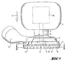
- the 1 to 3 is a grinder with a housing 1 and one in a working direction A represented by a motor M driven spindle 2.
- a tool holder 4 On that Free end 3 of the drive spindle 2 projecting from the housing 1 is a tool holder 4 provided that at the free end 3 of a connecting to the housing 1 suction hood 5 is included.
- the suction hood 5 is open towards the tool holder 4.
- the dust curtain 7 has several in the longitudinal direction L of the drive spindle 2 extending guide elements 8.
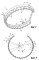
- the guide elements 8 point transversely to the longitudinal direction L of the drive spindle 2, for example an essentially quadrangular cross-section, with a larger longitudinal extension a than the transverse extension b.
- the longitudinal extension a advantageously corresponds about 17 times the width extension b.
- the guiding elements are opposite the circumferential direction by an angle of inclination ⁇ of about 18 ° inclined in the working direction A. This means that the longitudinal extension a of the guide elements 8 compared to a tagente t is inclined at the point of contact p with the outer circumference by the angle of inclination ⁇ .
- Adjacent guide elements 8 partially overlap in the radial projection area of the drive spindle 2 in one Overlap angle Y of about 5 ° in the working direction A.
- Adjacent guide elements (8) by 0.2 to 0.7 times their longitudinal extent a.
- annular support member 10 is provided, for example in one piece with the guide elements 8 is formed.
- the support member 10 is preferably by a fastener a snap device 11, releasably connectable to the housing 1.
- Both the support element 10 and the guide elements 8 are made of an elastic material, for example Rubber, manufactured.
- the snap device 11 has a hook-shaped tongue 12 with a hook element 13 and one arranged on the housing 1 engages with the hook element 13 bringable recess.
- the suction hood 5 has a connection for connecting a vacuum source, not shown Suction nozzle 14, for example by means of a suction hose with the vacuum source is connectable.
Landscapes
- Engineering & Computer Science (AREA)
- Mechanical Engineering (AREA)
- Grinding-Machine Dressing And Accessory Apparatuses (AREA)
- Finish Polishing, Edge Sharpening, And Grinding By Specific Grinding Devices (AREA)
- Disintegrating Or Milling (AREA)
- Carbon And Carbon Compounds (AREA)
Abstract
Description
der Luftströmung im offenen Randbereich der Absaughaube sichergestellt. Die Leitelemente gewährleisten durch ihre Dimensionierung und Anordnung einen optimalen Strömungsverlauf.
Der Neigungswinkel beträgt vorteilhafterweise zwischen 5° bis 25°, um eine optimale Ausrichtung der Leitelemente sicherzustellen.
- Fig. 1
- eine teilweise Seitenansicht des erfindungsgemässen Schleifgeräts;
- Fig. 2
- eine perspektivische Ansicht des in Fig. 1 dargestellten Staubvorhangs;
- Fig. 3
- einen quer zur Antriebsspindel verlaufenden Querschnitt des in Fig. 2 dargestellten Staubvorhangs gemäss der Ebene III-II in Fig. 1;
Claims (10)
dadurch gekennzeichnet, dass die Leitelemente (8) quer zur Längsrichtung (L) der Antriebsspindel (2) einen Querschnitt, mit einer grösseren Längserstreckung (a) als die quer dazu verlaufende Breiterstreckung (b) aufweisen.
Applications Claiming Priority (2)
| Application Number | Priority Date | Filing Date | Title |
|---|---|---|---|
| DE10162631 | 2001-12-20 | ||
| DE10162631A DE10162631A1 (de) | 2001-12-20 | 2001-12-20 | Schleifgerät mit Absaughaube |
Publications (2)
| Publication Number | Publication Date |
|---|---|
| EP1321230A1 true EP1321230A1 (de) | 2003-06-25 |
| EP1321230B1 EP1321230B1 (de) | 2011-06-15 |
Family
ID=7709945
Family Applications (1)
| Application Number | Title | Priority Date | Filing Date |
|---|---|---|---|
| EP02406075A Expired - Lifetime EP1321230B1 (de) | 2001-12-20 | 2002-12-09 | Schleifgerät mit Absaughaube |
Country Status (4)
| Country | Link |
|---|---|
| EP (1) | EP1321230B1 (de) |
| AT (1) | ATE512763T1 (de) |
| DE (1) | DE10162631A1 (de) |
| PL (1) | PL202773B1 (de) |
Cited By (2)
| Publication number | Priority date | Publication date | Assignee | Title |
|---|---|---|---|---|
| WO2008088926A1 (en) * | 2007-01-12 | 2008-07-24 | I.T., Inc. | Hood plates for handheld grinding tools |
| EP3705229A1 (de) * | 2019-03-04 | 2020-09-09 | Hilti Aktiengesellschaft | Staubhaubenerweiterungsvorrichtung und system umfassend eine solche staubhaubenerweiterungsvorrichtung und einen adapter |
Citations (2)
| Publication number | Priority date | Publication date | Assignee | Title |
|---|---|---|---|---|
| US4099328A (en) | 1977-07-20 | 1978-07-11 | Schlemmer John E | Machine for removing floor covering |
| CH681776A5 (en) | 1990-04-23 | 1993-05-28 | Heinz Baehni | Electric floor cleaning and polishing machine - has floating ring with cleaning brush or lamella crown and suction hose connection for removing dust or water from floor surface. |
-
2001
- 2001-12-20 DE DE10162631A patent/DE10162631A1/de not_active Ceased
-
2002
- 2002-12-09 EP EP02406075A patent/EP1321230B1/de not_active Expired - Lifetime
- 2002-12-09 AT AT02406075T patent/ATE512763T1/de active
- 2002-12-19 PL PL357898A patent/PL202773B1/pl unknown
Patent Citations (2)
| Publication number | Priority date | Publication date | Assignee | Title |
|---|---|---|---|---|
| US4099328A (en) | 1977-07-20 | 1978-07-11 | Schlemmer John E | Machine for removing floor covering |
| CH681776A5 (en) | 1990-04-23 | 1993-05-28 | Heinz Baehni | Electric floor cleaning and polishing machine - has floating ring with cleaning brush or lamella crown and suction hose connection for removing dust or water from floor surface. |
Cited By (5)
| Publication number | Priority date | Publication date | Assignee | Title |
|---|---|---|---|---|
| WO2008088926A1 (en) * | 2007-01-12 | 2008-07-24 | I.T., Inc. | Hood plates for handheld grinding tools |
| US7625265B2 (en) | 2007-01-12 | 2009-12-01 | I.T., Inc. | Hood plates for handheld grinding tools |
| EP3705229A1 (de) * | 2019-03-04 | 2020-09-09 | Hilti Aktiengesellschaft | Staubhaubenerweiterungsvorrichtung und system umfassend eine solche staubhaubenerweiterungsvorrichtung und einen adapter |
| WO2020178072A1 (de) * | 2019-03-04 | 2020-09-10 | Hilti Aktiengesellschaft | Staubhaubenerweiterungsvorrichtung und system umfassend eine solche staubhaubenerweiterungsvorrichtung und einen adapter |
| US12397395B2 (en) | 2019-03-04 | 2025-08-26 | Hilti Aktiengesellschaft | Chamfering dust hood extension device and adapter |
Also Published As
| Publication number | Publication date |
|---|---|
| DE10162631A1 (de) | 2003-07-10 |
| PL202773B1 (pl) | 2009-07-31 |
| EP1321230B1 (de) | 2011-06-15 |
| PL357898A1 (en) | 2003-06-30 |
| ATE512763T1 (de) | 2011-07-15 |
Similar Documents
| Publication | Publication Date | Title |
|---|---|---|
| DE69302813T2 (de) | Rotor für gasturbinen | |
| DE4218396B4 (de) | Filtereinrichtung, insbesondere zum Filtrieren der Ansaugluft eines Verbrennungsmotors | |
| DE2928914C2 (de) | Gerät zur Unterwasserreinigung | |
| EP0710527A2 (de) | Handwerkzeugmaschine zur Flächenbearbeitung | |
| DE4105336C2 (de) | Saugreinigungswerkzeug | |
| DE19936555A1 (de) | Staubschutzhaube für Oberflächenschleifgerät | |
| DE102010045994A1 (de) | Handgeführtes Arbeitsgerät | |
| EP1854583A1 (de) | Absaugvorrichtung für ein Abbauwerkzeuggerät | |
| DE102006000212A1 (de) | Absaugvorrichtung für ein Abbauwerkzeuggerät | |
| DE20203683U1 (de) | Handhobelmaschine | |
| EP0215476B1 (de) | Rotationsschleifgerät mit Staubabsaugvorrichtung | |
| DE2635405C3 (de) | Anordnung zur Staubabsaugung beim Vortrieb von Tunneln und Strecken mit Hilfe von Vortriebsmaschinen | |
| DE19945060B4 (de) | Schleifhandwerkzeugmaschine | |
| EP3176920A2 (de) | Abdeckvorrichtung für ein elektronikgehäuse eines elektromotors | |
| DE10162631A1 (de) | Schleifgerät mit Absaughaube | |
| EP0916453B1 (de) | Absaugvorrichtung für handgeführtes Werkzeugggerät | |
| EP2106327A1 (de) | Handgeführte werkzeugmaschine | |
| EP1925401B1 (de) | Motorgetriebenes Handschleifgerät mit verstellbarer Absaugeinrichtung | |
| EP2070651A1 (de) | Schleifteller und Schleifblatt | |
| DE69604573T2 (de) | Selbstreinigendes filter für pneumatische kreislaufe | |
| DE19951479B4 (de) | Saugvorrichtung für ein Werkzeug | |
| EP2062682A1 (de) | Staubabsaugung für eine Handwerkzeugmaschine | |
| CH674686A5 (de) | ||
| DE3501451A1 (de) | Vorrichtung zur beheizung von fahrgastraeumen o.dgl., insbesondere in omnibussen | |
| EP1714734B1 (de) | Staubabsaugeinrichtung zur lösbaren Anbringung an einem Werkzeuggerät, mit schiebenden Ansaugbereich |
Legal Events
| Date | Code | Title | Description |
|---|---|---|---|
| PUAI | Public reference made under article 153(3) epc to a published international application that has entered the european phase |
Free format text: ORIGINAL CODE: 0009012 |
|
| AK | Designated contracting states |
Designated state(s): AT BE BG CH CY CZ DE DK EE ES FI FR GB GR IE IT LI LU MC NL PT SE SI SK TR |
|
| AX | Request for extension of the european patent |
Extension state: AL LT LV MK RO |
|
| 17P | Request for examination filed |
Effective date: 20031229 |
|
| AKX | Designation fees paid |
Designated state(s): AT BE BG CH CY CZ DE DK EE ES FI FR GB GR IE IT LI LU MC NL PT SE SI SK TR |
|
| 17Q | First examination report despatched |
Effective date: 20081117 |
|
| GRAP | Despatch of communication of intention to grant a patent |
Free format text: ORIGINAL CODE: EPIDOSNIGR1 |
|
| GRAS | Grant fee paid |
Free format text: ORIGINAL CODE: EPIDOSNIGR3 |
|
| GRAA | (expected) grant |
Free format text: ORIGINAL CODE: 0009210 |
|
| AK | Designated contracting states |
Kind code of ref document: B1 Designated state(s): AT BE BG CH CY CZ DE DK EE ES FI FR GB GR IE IT LI LU MC NL PT SE SI SK TR |
|
| REG | Reference to a national code |
Ref country code: GB Ref legal event code: FG4D Free format text: NOT ENGLISH Ref country code: CH Ref legal event code: EP |
|
| REG | Reference to a national code |
Ref country code: IE Ref legal event code: FG4D Free format text: LANGUAGE OF EP DOCUMENT: GERMAN |
|
| REG | Reference to a national code |
Ref country code: DE Ref legal event code: R096 Ref document number: 50215089 Country of ref document: DE Effective date: 20110721 |
|
| REG | Reference to a national code |
Ref country code: SE Ref legal event code: TRGR |
|
| REG | Reference to a national code |
Ref country code: NL Ref legal event code: VDEP Effective date: 20110615 |
|
| PG25 | Lapsed in a contracting state [announced via postgrant information from national office to epo] |
Ref country code: GR Free format text: LAPSE BECAUSE OF FAILURE TO SUBMIT A TRANSLATION OF THE DESCRIPTION OR TO PAY THE FEE WITHIN THE PRESCRIBED TIME-LIMIT Effective date: 20110916 Ref country code: CY Free format text: LAPSE BECAUSE OF FAILURE TO SUBMIT A TRANSLATION OF THE DESCRIPTION OR TO PAY THE FEE WITHIN THE PRESCRIBED TIME-LIMIT Effective date: 20110615 Ref country code: SI Free format text: LAPSE BECAUSE OF FAILURE TO SUBMIT A TRANSLATION OF THE DESCRIPTION OR TO PAY THE FEE WITHIN THE PRESCRIBED TIME-LIMIT Effective date: 20110615 Ref country code: FI Free format text: LAPSE BECAUSE OF FAILURE TO SUBMIT A TRANSLATION OF THE DESCRIPTION OR TO PAY THE FEE WITHIN THE PRESCRIBED TIME-LIMIT Effective date: 20110615 |
|
| PG25 | Lapsed in a contracting state [announced via postgrant information from national office to epo] |
Ref country code: NL Free format text: LAPSE BECAUSE OF FAILURE TO SUBMIT A TRANSLATION OF THE DESCRIPTION OR TO PAY THE FEE WITHIN THE PRESCRIBED TIME-LIMIT Effective date: 20110615 |
|
| REG | Reference to a national code |
Ref country code: IE Ref legal event code: FD4D |
|
| PG25 | Lapsed in a contracting state [announced via postgrant information from national office to epo] |
Ref country code: EE Free format text: LAPSE BECAUSE OF FAILURE TO SUBMIT A TRANSLATION OF THE DESCRIPTION OR TO PAY THE FEE WITHIN THE PRESCRIBED TIME-LIMIT Effective date: 20110615 Ref country code: PT Free format text: LAPSE BECAUSE OF FAILURE TO SUBMIT A TRANSLATION OF THE DESCRIPTION OR TO PAY THE FEE WITHIN THE PRESCRIBED TIME-LIMIT Effective date: 20111017 Ref country code: CZ Free format text: LAPSE BECAUSE OF FAILURE TO SUBMIT A TRANSLATION OF THE DESCRIPTION OR TO PAY THE FEE WITHIN THE PRESCRIBED TIME-LIMIT Effective date: 20110615 Ref country code: IE Free format text: LAPSE BECAUSE OF FAILURE TO SUBMIT A TRANSLATION OF THE DESCRIPTION OR TO PAY THE FEE WITHIN THE PRESCRIBED TIME-LIMIT Effective date: 20110615 |
|
| PG25 | Lapsed in a contracting state [announced via postgrant information from national office to epo] |
Ref country code: SK Free format text: LAPSE BECAUSE OF FAILURE TO SUBMIT A TRANSLATION OF THE DESCRIPTION OR TO PAY THE FEE WITHIN THE PRESCRIBED TIME-LIMIT Effective date: 20110615 |
|
| PLBE | No opposition filed within time limit |
Free format text: ORIGINAL CODE: 0009261 |
|
| STAA | Information on the status of an ep patent application or granted ep patent |
Free format text: STATUS: NO OPPOSITION FILED WITHIN TIME LIMIT |
|
| 26N | No opposition filed |
Effective date: 20120316 |
|
| PG25 | Lapsed in a contracting state [announced via postgrant information from national office to epo] |
Ref country code: DK Free format text: LAPSE BECAUSE OF FAILURE TO SUBMIT A TRANSLATION OF THE DESCRIPTION OR TO PAY THE FEE WITHIN THE PRESCRIBED TIME-LIMIT Effective date: 20110615 |
|
| BERE | Be: lapsed |
Owner name: HILTI AKTIENGESELLSCHAFT Effective date: 20111231 |
|
| REG | Reference to a national code |
Ref country code: DE Ref legal event code: R097 Ref document number: 50215089 Country of ref document: DE Effective date: 20120316 |
|
| PG25 | Lapsed in a contracting state [announced via postgrant information from national office to epo] |
Ref country code: MC Free format text: LAPSE BECAUSE OF NON-PAYMENT OF DUE FEES Effective date: 20111231 |
|
| REG | Reference to a national code |
Ref country code: CH Ref legal event code: PL |
|
| GBPC | Gb: european patent ceased through non-payment of renewal fee |
Effective date: 20111209 |
|
| PG25 | Lapsed in a contracting state [announced via postgrant information from national office to epo] |
Ref country code: LI Free format text: LAPSE BECAUSE OF NON-PAYMENT OF DUE FEES Effective date: 20111231 Ref country code: GB Free format text: LAPSE BECAUSE OF NON-PAYMENT OF DUE FEES Effective date: 20111209 Ref country code: CH Free format text: LAPSE BECAUSE OF NON-PAYMENT OF DUE FEES Effective date: 20111231 Ref country code: BE Free format text: LAPSE BECAUSE OF NON-PAYMENT OF DUE FEES Effective date: 20111231 |
|
| REG | Reference to a national code |
Ref country code: AT Ref legal event code: MM01 Ref document number: 512763 Country of ref document: AT Kind code of ref document: T Effective date: 20111209 |
|
| PG25 | Lapsed in a contracting state [announced via postgrant information from national office to epo] |
Ref country code: ES Free format text: LAPSE BECAUSE OF FAILURE TO SUBMIT A TRANSLATION OF THE DESCRIPTION OR TO PAY THE FEE WITHIN THE PRESCRIBED TIME-LIMIT Effective date: 20110926 |
|
| PG25 | Lapsed in a contracting state [announced via postgrant information from national office to epo] |
Ref country code: LU Free format text: LAPSE BECAUSE OF NON-PAYMENT OF DUE FEES Effective date: 20111209 |
|
| PG25 | Lapsed in a contracting state [announced via postgrant information from national office to epo] |
Ref country code: AT Free format text: LAPSE BECAUSE OF NON-PAYMENT OF DUE FEES Effective date: 20111209 Ref country code: BG Free format text: LAPSE BECAUSE OF FAILURE TO SUBMIT A TRANSLATION OF THE DESCRIPTION OR TO PAY THE FEE WITHIN THE PRESCRIBED TIME-LIMIT Effective date: 20110915 |
|
| PG25 | Lapsed in a contracting state [announced via postgrant information from national office to epo] |
Ref country code: TR Free format text: LAPSE BECAUSE OF FAILURE TO SUBMIT A TRANSLATION OF THE DESCRIPTION OR TO PAY THE FEE WITHIN THE PRESCRIBED TIME-LIMIT Effective date: 20110615 |
|
| REG | Reference to a national code |
Ref country code: FR Ref legal event code: PLFP Year of fee payment: 14 |
|
| REG | Reference to a national code |
Ref country code: FR Ref legal event code: PLFP Year of fee payment: 15 |
|
| REG | Reference to a national code |
Ref country code: FR Ref legal event code: PLFP Year of fee payment: 16 |
|
| PGFP | Annual fee paid to national office [announced via postgrant information from national office to epo] |
Ref country code: FR Payment date: 20211224 Year of fee payment: 20 Ref country code: DE Payment date: 20211210 Year of fee payment: 20 Ref country code: SE Payment date: 20211221 Year of fee payment: 20 |
|
| PGFP | Annual fee paid to national office [announced via postgrant information from national office to epo] |
Ref country code: IT Payment date: 20211224 Year of fee payment: 20 |
|
| REG | Reference to a national code |
Ref country code: DE Ref legal event code: R071 Ref document number: 50215089 Country of ref document: DE |
|
| REG | Reference to a national code |
Ref country code: SE Ref legal event code: EUG |