EP1321086A2 - Accessoire à brosse pour appareils electriques, en particulier aspirateurs, balais electriques ou similaires, muni d'un conduit d'aspiration - Google Patents
Accessoire à brosse pour appareils electriques, en particulier aspirateurs, balais electriques ou similaires, muni d'un conduit d'aspiration Download PDFInfo
- Publication number
- EP1321086A2 EP1321086A2 EP02028122A EP02028122A EP1321086A2 EP 1321086 A2 EP1321086 A2 EP 1321086A2 EP 02028122 A EP02028122 A EP 02028122A EP 02028122 A EP02028122 A EP 02028122A EP 1321086 A2 EP1321086 A2 EP 1321086A2
- Authority
- EP
- European Patent Office
- Prior art keywords
- brush accessory
- accessory according
- flat box
- brush
- face
- Prior art date
- Legal status (The legal status is an assumption and is not a legal conclusion. Google has not performed a legal analysis and makes no representation as to the accuracy of the status listed.)
- Withdrawn
Links
- 244000007853 Sarothamnus scoparius Species 0.000 title claims abstract description 9
- 230000008878 coupling Effects 0.000 claims abstract description 10
- 238000010168 coupling process Methods 0.000 claims abstract description 10
- 238000005859 coupling reaction Methods 0.000 claims abstract description 10
- 238000004140 cleaning Methods 0.000 claims abstract description 7
- 239000000463 material Substances 0.000 claims abstract description 5
- 239000011538 cleaning material Substances 0.000 claims description 8
- 230000006835 compression Effects 0.000 claims description 2
- 238000007906 compression Methods 0.000 claims description 2
- 239000004753 textile Substances 0.000 claims description 2
- 230000000284 resting effect Effects 0.000 description 4
- 230000013011 mating Effects 0.000 description 2
- 239000000428 dust Substances 0.000 description 1
- 230000000694 effects Effects 0.000 description 1
- 239000012535 impurity Substances 0.000 description 1
- 230000000670 limiting effect Effects 0.000 description 1
- 230000007774 longterm Effects 0.000 description 1
- 230000004048 modification Effects 0.000 description 1
- 238000012986 modification Methods 0.000 description 1
- 239000002245 particle Substances 0.000 description 1
- 230000035515 penetration Effects 0.000 description 1
- 239000002699 waste material Substances 0.000 description 1
Images


Classifications
-
- A—HUMAN NECESSITIES
- A47—FURNITURE; DOMESTIC ARTICLES OR APPLIANCES; COFFEE MILLS; SPICE MILLS; SUCTION CLEANERS IN GENERAL
- A47L—DOMESTIC WASHING OR CLEANING; SUCTION CLEANERS IN GENERAL
- A47L9/00—Details or accessories of suction cleaners, e.g. mechanical means for controlling the suction or for effecting pulsating action; Storing devices specially adapted to suction cleaners or parts thereof; Carrying-vehicles specially adapted for suction cleaners
- A47L9/02—Nozzles
- A47L9/06—Nozzles with fixed, e.g. adjustably fixed brushes or the like
-
- A—HUMAN NECESSITIES
- A47—FURNITURE; DOMESTIC ARTICLES OR APPLIANCES; COFFEE MILLS; SPICE MILLS; SUCTION CLEANERS IN GENERAL
- A47L—DOMESTIC WASHING OR CLEANING; SUCTION CLEANERS IN GENERAL
- A47L9/00—Details or accessories of suction cleaners, e.g. mechanical means for controlling the suction or for effecting pulsating action; Storing devices specially adapted to suction cleaners or parts thereof; Carrying-vehicles specially adapted for suction cleaners
- A47L9/02—Nozzles
- A47L9/06—Nozzles with fixed, e.g. adjustably fixed brushes or the like
- A47L9/0633—Nozzles with fixed, e.g. adjustably fixed brushes or the like with retractable brushes, combs, lips or pads
- A47L9/064—Nozzles with fixed, e.g. adjustably fixed brushes or the like with retractable brushes, combs, lips or pads actuating means therefor
- A47L9/0653—Nozzles with fixed, e.g. adjustably fixed brushes or the like with retractable brushes, combs, lips or pads actuating means therefor with mechanical actuation, e.g. using a lever
Definitions
- the present invention relates to a brush accessory for electrical appliances, particularly vacuum cleaners, electric brooms and the like, provided with a suction tube.
- These known accessories substantially comprise a narrow-tipped lance, a wide nozzle optionally provided with bristles, or an actual box-like brush: all these accessories are internally hollow and have a rear opening for fitting, as mentioned, at the end of the suction tube with which said electrical appliances are normally provided.
- some of said known brushes have, at the connection of the rear opening on the brush body, an articulation that allows the rotation on one plane of the tube, which acts not only as an element for the passage of the collected impurities toward the inside of the collection region of the electrical appliance but also as a handling grip for the user.
- This articulation associated with a bend of the rear opening for the tube at an obtuse angle, allows to maneuver the brush during its use, making it rotate over the surface to be cleaned in order to allow it to pass edgeways even within substantially confined spaces.
- each one of said accessories has a specific function and is provided, for this reason, as equipment for a single electrical appliance and must be changed in each instance during work.
- the aim of the present invention is to eliminate the above-mentioned drawbacks of the known art, by providing a brush accessory for electrical appliances, particularly vacuum cleaners, electric brooms and the like, which have a suction tube that allows to clean joined horizontal and vertical surfaces with the same accuracy and ease while using a single accessory.
- an object of the present invention is to provide a brush accessory that is simple, safe in use, effective in operation and has a relatively low cost.
- the present brush accessory for electrical appliances particularly vacuum cleaners, electric brooms and the like, provided with a suction tube
- said accessory being constituted by a substantially flat box-like body that has a polygonal plan shape, by a layer of material for cleaning a surface, which is supported on a face of said flat body that is considered as the lower face, by at least one articulated coupling for said suction tube, characterized in that said polygonal box-like body forms at least one slender and elongated vertex for passing in confined spaces and is provided with a means for supporting and guiding said brush accessory located on the upper opposite face thereof.
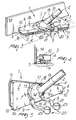
- the reference numeral 1 generally designates a brush accessory for electrical appliances, particularly vacuum cleaners, electric brooms and the like, which are provided with a suction tube 2, said accessory being essentially constituted by a substantially flat box-like body 3 whose plan shape is polygonal and, in the specific case, triangular.
- a layer 5 of material for cleaning a surface "S1" is coupled on a lower face 4 of the box-like body 3, while on an opposite upper face 6 there is an articulated coupling 7 for the suction tube 2.
- the triangular box-like body 3 forms at least one slender and elongated vertex 8, which is suitable to be inserted in tight spaces; moreover, the box-like body 3 has a means 9 for supporting and guiding the brush accessory 1, which is located on the upper face 6 thereof.
- the flat box-like body 3 has, on at least one side 3a, two freely rotating wheels 10, whose axes are perpendicular to the faces 4 and 6, for resting and sliding on surfaces "S2" that meet at an angle the surface "S1" to be cleaned.
- the layer 5 of cleaning material is constituted, in a first possible embodiment of the invention, by a plurality of bristles 11 (Figures 3 to 7), which protrude from the lower face 4; in a second possible embodiment, the layer 5 can be constituted ( Figures 1 and 2), by at least one textile or sponge-like pad 12 which is substantially laminar and rigidly coupled to the lower face 4.
- the articulated coupling 7 is constituted by a head 13, which is mounted so that it can rotate to the left and to the right on the upper face 6 of the flat box-like body 3, with a rotation axis that is perpendicular thereto and is provided with at least one slotted opening 14 which is located laterally and in an upper region and is substantially vertical.
- a tube-like rear opening 15 protrudes from the head 13 and is connected, at one end, to corresponding means 16 for connection to the inside of the flat box-like body 3; the tube-like rear opening 15 passes through the slotted opening 14, oscillates therein and constitutes the connection, at the opposite end, for a mating end of the suction tube 3.
- the head 13 is substantially shaped like a spherical dome and is provided, at its base, with a selector 17, which is suitable to lock or release its rotation.
- the means 16 for connecting the end of the tube-like rear opening 15 are constituted by an extension of said end, which forms a second dome 18 that is rigidly coupled thereto and is mounted in sliding contact inside the spherical dome that constitutes the head 13.
- the supporting and guiding means 9 is constituted by at least one fork 19, which has two prongs which are mutually joined at the base by a connecting pivot (not shown in the drawings) and is articulated to the flat box-like body 3; said base of the fork 19 is parallel to the side 3a provided with the two freely rotating wheels 10.
- the fork 19 can be arranged alternately in an upright position that is perpendicular to the upper face 6 ( Figures 2, 5, 6) or in a reclined position ( Figures 1, 3 and 7), which is substantially parallel and transverse with respect to the upper face 6.
- the prongs of the fork 19 protrude from said upper face and are both provided with respective elements 20 for resting and sliding on a surface S1 or S2; said elements are constituted, for each prong, by at least one ball 21, which is contained so that it can rotate freely in a respective receptacle 22 which is shaped like a sleeve 23 and is rigidly coupled to the free end of the respective prong, with an axis that is substantially perpendicular thereto; the sleeve 23 is shorter than the diameter of the ball 21, so that the polar portions of the ball 21 protrude from the open ends of said sleeve.
- both the spherical dome-shaped head 13 and the fork 19 can be accommodated, respectively in a stable fashion and in a reclined arrangement, in a corresponding hollow seat 24 provided to size in the upper face 6 of the flat box-like body 3: the prongs of the fork 19, when said fork is in the reclined position, lie on either side of the spherical dome-shaped head 13 and are substantially co-planar with respect to the upper face 6.
- the flat box-like body 3 is composed of two half-bodies which interpenetrate telescopically; at least one of said half-bodies, i.e., the lower half-body, designated by the reference numeral 104, can be moved parallel to itself with respect to the other upper half-body, designated by the reference numeral 103, which contains the preceding half-body and supports the articulated coupling 7 and the supporting and guiding means 9, while the second lower half-body 104 bears the layer 5 of cleaning material.
- Elastic means 105 for contrasting the movement of the lower half-body 104 with respect to the upper half-body 103 are interposed between the upper half-body 103 and the lower half-body 104.
- the selector 17 is constituted by a half-ring 25, in which the diametrical ends 26 are articulated at 27 to the spherical dome-shaped head 13; in the preferred embodiment of the invention, both ends 26 of the half-ring 25 have respective pins 28, which protrude at right angles with respect to the half-ring 25 and are directed toward the lower half-body 104, which has a double pair of openings, which are alternately through openings, designated by the reference numeral 29, and concave blind openings, designated by the reference numeral 30, for engagement with the pins 28; the half-ring 25 can rotate about the articulations 27 of the diametrical ends 26, between a position in which it is raised with respect to the upper half-body 103, in which the pins 28 are disengaged from all the openings 29 and 30, consequently allowing the free rotation of the head 13 with respect to the flat box-like body 3, and a lowered position that is flush with the upper face 6 and in which the pins 28 are in a configuration for engaging a pair of said openings,
- the lowering of the half-ring 25 produces a thrust on the lower half-body 104 and the corresponding sliding thereof toward the outside of the box-like body 3 with respect to the upper half-body 103; in this manner, the layer 5 of cleaning material protrudes stably from the lower portion of the box-like body 3.
- the elastic contrast means 105 are constituted by at least one helical spring 106, which can be loaded by compression and is interposed between the upper half-body 103 and the lower half-body 104; the turns of the spring 106 are wound coaxially on a pivot 107, which protrudes at right angles from the lower face of the upper half-body 103 and passes through an opening that is coaxial to the pivot 107 (not visible in the drawings) and is formed in the lower half-body 104; the free end of the pivot 107 forms a receptacle 108 for containing one end of the spring 106, whose opposite end rests on the lower face of the upper half-body 103.
- the operation of the brush accessory 1 according to the present invention is as follows: said brush accessory is fitted onto the end of a suction tube 2 of an electrical appliance, for example a vacuum cleaner, by mutually coupling in a bayonet fashion the mating ends of the suction tube 2 and the end of the rear opening 15.
- an electrical appliance for example a vacuum cleaner
- the user then chooses whether to use the brush accessory 1 so that it can float freely or to fix the angular position of the flat box-like body 3 with respect to the rear opening 15 and therefore with respect to the suction tube 2, which also acts as a handling grip.
- the lowering of the half-ring 25 causes the penetration of said pins into the openings, locking said rotation, but with no effect on the lower half-body 104 and therefore on the layer 5 of cleaning material, which therefore remains contained within the box-like body 3; in the alternative case of alignment between the pins 28 and the concave and blind openings 30, the lowering of the half-ring 25 causes the mutual engagement of the pins 28 and said concave and blind openings 30, and the consequent thrust of said pins on said openings: the thrust determines a telescopic sliding of the lower half-body 104 with respect to the upper half-body 103 and the exit of the layer 5 of cleaning material from the base of the box-like body 3.
- the thrust occurs in contrast with the spring 106, which is compressed and tends to return the lower half-body 104, contained in the upper half-body 103, to its normal arrangement.
- the fork 19 is left in the reclined position, so that the prongs are contained within the hollow seat 24 and protrude from the side that lies opposite the side 3a, so that the balls 21 rest on the surface S1 together with the bristles 11 or the pad 12, giving greater stability to the brush accessory 1 and keeping it constantly parallel to said surface S1 during rubbing.
- the fork 19 is raised and arranged vertically with respect to the faces 6 and 4 of the flat box-like body 3; this allows to move closer with the side 3a thereof directed toward the vertical surface S2 and to rest on said surface both the wheels 10 and the balls 21, so as to be able to slide easily back and forth the brush accessory 1, keeping it stable during the back-and-forth sliding.
- the brush accessory 1 When the surface to be cleaned is vertical (S2), the brush accessory 1 is turned through 90°, making the head 13 rotate so as to arrange the slot 14 so that it is directed diagonally upward.
- the fork 19 is still kept in the position in which it is raised from its hollow seat 24 so as to provide, with the balls 21, support on the horizontal surface S1 during back-and-forth sliding.
- the flat box-like body 3 is thus arranged edgeways, making the bristles 11 or the pad 12 adhere to the vertical surface S2; the back-and-forth sliding of the brush accessory 1 is also facilitated by the wheels 10 which, by performing a translational motion while resting on said horizontal flat surface S1, keep the box-like body 3 slightly raised from it and eliminate all friction.
- the angular mutual position of the rear opening 15 and the box-like body 3 is determined by the conditions of use of the brush accessory 1; for example, Figure 8 shows the configuration of minimum possible transverse space occupation, in which the rear opening 15 is directed away from the slender vertex 8, in order to be able to pass said vertex between two contiguous elements, such as two pieces of furniture; Figures 1 to 6 instead illustrate the configuration of maximum transverse space occupation, in which the rear opening 15 is arranged transversely to the flat box-like body 3, which in this manner can have a larger active front.
- the materials used, as well as the shapes and the dimensions, may be any according to requirements without thereby abandoning the scope of the protection of the present invention.
Landscapes
- Engineering & Computer Science (AREA)
- Mechanical Engineering (AREA)
- Nozzles For Electric Vacuum Cleaners (AREA)
- Brushes (AREA)
- Massaging Devices (AREA)
Applications Claiming Priority (2)
| Application Number | Priority Date | Filing Date | Title |
|---|---|---|---|
| ITMO20010255 | 2001-12-21 | ||
| IT2001MO000255A ITMO20010255A1 (it) | 2001-12-21 | 2001-12-21 | Accessorio spazzola per elettrodomestici, in particolare aspirapolvere, scope elettriche e simili dotati di tubo aspirante |
Publications (2)
| Publication Number | Publication Date |
|---|---|
| EP1321086A2 true EP1321086A2 (fr) | 2003-06-25 |
| EP1321086A3 EP1321086A3 (fr) | 2004-08-18 |
Family
ID=11450941
Family Applications (1)
| Application Number | Title | Priority Date | Filing Date |
|---|---|---|---|
| EP02028122A Withdrawn EP1321086A3 (fr) | 2001-12-21 | 2002-12-18 | Accessoire à brosse pour appareils electriques, en particulier aspirateurs, balais electriques ou similaires, muni d'un conduit d'aspiration |
Country Status (2)
| Country | Link |
|---|---|
| EP (1) | EP1321086A3 (fr) |
| IT (1) | ITMO20010255A1 (fr) |
Cited By (3)
| Publication number | Priority date | Publication date | Assignee | Title |
|---|---|---|---|---|
| EP2995233A1 (fr) * | 2014-09-15 | 2016-03-16 | Indesit Company S.p.A. | Balai électrique réversible |
| JP2021013588A (ja) * | 2019-07-12 | 2021-02-12 | シャープ株式会社 | 電気掃除機の吸込口体およびそれを備えた電気掃除機 |
| US11937762B2 (en) | 2019-06-26 | 2024-03-26 | Milwaukee Electric Tool Corporation | Vacuum tools |
Citations (6)
| Publication number | Priority date | Publication date | Assignee | Title |
|---|---|---|---|---|
| DE657633C (de) * | 1936-08-15 | 1938-03-10 | Elektrolux Akt Ges | Kugelgelenk fuer Staubsaugermundstuecke |
| US4638527A (en) * | 1986-02-20 | 1987-01-27 | Fleischhauer Eugene T | Vacuum cleaner attachments |
| US5392491A (en) * | 1991-11-01 | 1995-02-28 | Gold Star Co., Ltd. | Cleaner head for a vacuum cleaner |
| US5509171A (en) * | 1994-12-07 | 1996-04-23 | Zejda; Frantisek | Vacuum cleaner bumper system |
| JPH10229959A (ja) * | 1997-02-18 | 1998-09-02 | Hideki Kimura | 掃除機 |
| WO2001003565A1 (fr) * | 1999-07-12 | 2001-01-18 | Moulinex S.A. | Suceur d'aspirateur de poussiere articule et aspirateur equipe d'un tel suceur |
-
2001
- 2001-12-21 IT IT2001MO000255A patent/ITMO20010255A1/it unknown
-
2002
- 2002-12-18 EP EP02028122A patent/EP1321086A3/fr not_active Withdrawn
Patent Citations (6)
| Publication number | Priority date | Publication date | Assignee | Title |
|---|---|---|---|---|
| DE657633C (de) * | 1936-08-15 | 1938-03-10 | Elektrolux Akt Ges | Kugelgelenk fuer Staubsaugermundstuecke |
| US4638527A (en) * | 1986-02-20 | 1987-01-27 | Fleischhauer Eugene T | Vacuum cleaner attachments |
| US5392491A (en) * | 1991-11-01 | 1995-02-28 | Gold Star Co., Ltd. | Cleaner head for a vacuum cleaner |
| US5509171A (en) * | 1994-12-07 | 1996-04-23 | Zejda; Frantisek | Vacuum cleaner bumper system |
| JPH10229959A (ja) * | 1997-02-18 | 1998-09-02 | Hideki Kimura | 掃除機 |
| WO2001003565A1 (fr) * | 1999-07-12 | 2001-01-18 | Moulinex S.A. | Suceur d'aspirateur de poussiere articule et aspirateur equipe d'un tel suceur |
Non-Patent Citations (1)
| Title |
|---|
| PATENT ABSTRACTS OF JAPAN vol. 1998, no. 14, 31 December 1998 (1998-12-31) & JP 10 229959 A (KIMURA HIDEKI), 2 September 1998 (1998-09-02) * |
Cited By (4)
| Publication number | Priority date | Publication date | Assignee | Title |
|---|---|---|---|---|
| EP2995233A1 (fr) * | 2014-09-15 | 2016-03-16 | Indesit Company S.p.A. | Balai électrique réversible |
| CN105411485A (zh) * | 2014-09-15 | 2016-03-23 | 英德斯特股份公司 | 可翻转的电动扫帚 |
| US11937762B2 (en) | 2019-06-26 | 2024-03-26 | Milwaukee Electric Tool Corporation | Vacuum tools |
| JP2021013588A (ja) * | 2019-07-12 | 2021-02-12 | シャープ株式会社 | 電気掃除機の吸込口体およびそれを備えた電気掃除機 |
Also Published As
| Publication number | Publication date |
|---|---|
| EP1321086A3 (fr) | 2004-08-18 |
| ITMO20010255A1 (it) | 2003-06-21 |
| ITMO20010255A0 (it) | 2001-12-21 |
Similar Documents
| Publication | Publication Date | Title |
|---|---|---|
| KR102238138B1 (ko) | 거치대 및 이를 포함하는 진공청소기 | |
| CN101869455B (zh) | 电动吸尘器 | |
| CN109715018B (zh) | 用于真空吸尘器的清洁头 | |
| US3815170A (en) | Cleaning nozzle attachment for a suction cleaner | |
| CN101564281B (zh) | 电动吸尘器 | |
| CN102232814B (zh) | 电动吸尘器 | |
| EP1222892B1 (fr) | Buse d'aspiration pour appareils de nettoyage tels que des aspirateurs, des brosses électriques ou similaires | |
| US8286299B2 (en) | Handheld canister vacuum cleaner | |
| SK64996A3 (en) | Vacuum cleaner electromotively driven with telescoping handle | |
| US11426049B2 (en) | Multi-surface spray mop and mop supporting stand | |
| EP1321086A2 (fr) | Accessoire à brosse pour appareils electriques, en particulier aspirateurs, balais electriques ou similaires, muni d'un conduit d'aspiration | |
| US8407853B1 (en) | High place vacuum cleaner attachment | |
| KR20220012727A (ko) | 진공청소기 | |
| KR20220012730A (ko) | 진공청소기 | |
| JP6540820B2 (ja) | 掃除具及びバキューム掃除機 | |
| EP0980667A2 (fr) | Balai à franges | |
| JP6763455B2 (ja) | 掃除具及びバキューム掃除機 | |
| JP7056700B2 (ja) | 掃除具及びコードレス型掃除機 | |
| KR100569350B1 (ko) | 진공청소기의 바퀴 장착구조 | |
| NZ740668B2 (en) | Cleaning tool and vacuum cleaner |
Legal Events
| Date | Code | Title | Description |
|---|---|---|---|
| PUAI | Public reference made under article 153(3) epc to a published international application that has entered the european phase |
Free format text: ORIGINAL CODE: 0009012 |
|
| AK | Designated contracting states |
Designated state(s): AT BE BG CH CY CZ DE DK EE ES FI FR GB GR IE IT LI LU MC NL PT SE SI SK TR |
|
| AX | Request for extension of the european patent |
Extension state: AL LT LV MK RO |
|
| PUAL | Search report despatched |
Free format text: ORIGINAL CODE: 0009013 |
|
| AK | Designated contracting states |
Kind code of ref document: A3 Designated state(s): AT BE BG CH CY CZ DE DK EE ES FI FR GB GR IE IT LI LU MC NL PT SE SI SK TR |
|
| AX | Request for extension of the european patent |
Extension state: AL LT LV MK RO |
|
| RIC1 | Information provided on ipc code assigned before grant |
Ipc: 7A 47L 9/02 B Ipc: 7A 47L 9/06 A |
|
| AKX | Designation fees paid | ||
| REG | Reference to a national code |
Ref country code: DE Ref legal event code: 8566 |
|
| STAA | Information on the status of an ep patent application or granted ep patent |
Free format text: STATUS: THE APPLICATION IS DEEMED TO BE WITHDRAWN |
|
| 18D | Application deemed to be withdrawn |
Effective date: 20050219 |