EP1320738B1 - Method and apparatus for leak testing closed containers - Google Patents
Method and apparatus for leak testing closed containers Download PDFInfo
- Publication number
- EP1320738B1 EP1320738B1 EP00960280A EP00960280A EP1320738B1 EP 1320738 B1 EP1320738 B1 EP 1320738B1 EP 00960280 A EP00960280 A EP 00960280A EP 00960280 A EP00960280 A EP 00960280A EP 1320738 B1 EP1320738 B1 EP 1320738B1
- Authority
- EP
- European Patent Office
- Prior art keywords
- signal
- force
- container
- biasing
- unit
- Prior art date
- Legal status (The legal status is an assumption and is not a legal conclusion. Google has not performed a legal analysis and makes no representation as to the accuracy of the status listed.)
- Expired - Lifetime
Links
- 238000012360 testing method Methods 0.000 title claims abstract description 100
- 238000000034 method Methods 0.000 title claims description 48
- 238000006243 chemical reaction Methods 0.000 claims description 19
- 238000005259 measurement Methods 0.000 claims description 9
- 238000012544 monitoring process Methods 0.000 claims description 8
- 238000012935 Averaging Methods 0.000 claims description 7
- 238000005070 sampling Methods 0.000 claims description 7
- IJGRMHOSHXDMSA-UHFFFAOYSA-N Atomic nitrogen Chemical compound N#N IJGRMHOSHXDMSA-UHFFFAOYSA-N 0.000 claims description 6
- 239000007788 liquid Substances 0.000 claims description 6
- 238000003860 storage Methods 0.000 claims description 6
- 238000004140 cleaning Methods 0.000 claims description 4
- 230000001419 dependent effect Effects 0.000 claims description 4
- 238000011010 flushing procedure Methods 0.000 claims description 4
- 239000007789 gas Substances 0.000 claims description 4
- 238000003754 machining Methods 0.000 claims description 3
- 229910052757 nitrogen Inorganic materials 0.000 claims description 3
- 238000007788 roughening Methods 0.000 claims description 3
- 238000010438 heat treatment Methods 0.000 claims description 2
- 238000002847 impedance measurement Methods 0.000 claims 1
- 238000010586 diagram Methods 0.000 description 6
- 238000004519 manufacturing process Methods 0.000 description 4
- 238000001514 detection method Methods 0.000 description 3
- 230000000630 rising effect Effects 0.000 description 3
- 230000006835 compression Effects 0.000 description 2
- 238000007906 compression Methods 0.000 description 2
- 238000009826 distribution Methods 0.000 description 2
- 238000005530 etching Methods 0.000 description 2
- 238000011156 evaluation Methods 0.000 description 2
- 235000011837 pasties Nutrition 0.000 description 2
- 238000003825 pressing Methods 0.000 description 2
- 238000003466 welding Methods 0.000 description 2
- 230000003044 adaptive effect Effects 0.000 description 1
- 230000003321 amplification Effects 0.000 description 1
- 238000009530 blood pressure measurement Methods 0.000 description 1
- 238000011161 development Methods 0.000 description 1
- 238000002474 experimental method Methods 0.000 description 1
- 230000007774 longterm Effects 0.000 description 1
- 239000000463 material Substances 0.000 description 1
- 238000000691 measurement method Methods 0.000 description 1
- 238000003199 nucleic acid amplification method Methods 0.000 description 1
- 238000005488 sandblasting Methods 0.000 description 1
- 238000007789 sealing Methods 0.000 description 1
- 238000004904 shortening Methods 0.000 description 1
- 230000003068 static effect Effects 0.000 description 1
- 230000001052 transient effect Effects 0.000 description 1
- 230000001960 triggered effect Effects 0.000 description 1
Images


Classifications
-
- G—PHYSICS
- G01—MEASURING; TESTING
- G01M—TESTING STATIC OR DYNAMIC BALANCE OF MACHINES OR STRUCTURES; TESTING OF STRUCTURES OR APPARATUS, NOT OTHERWISE PROVIDED FOR
- G01M3/00—Investigating fluid-tightness of structures
- G01M3/02—Investigating fluid-tightness of structures by using fluid or vacuum
- G01M3/36—Investigating fluid-tightness of structures by using fluid or vacuum by detecting change in dimensions of the structure being tested
- G01M3/363—Investigating fluid-tightness of structures by using fluid or vacuum by detecting change in dimensions of the structure being tested the structure being removably mounted in a test cell
Definitions
- the present invention is directed to a method for leak testing closed containers with at least one flexible wall area and to a leak testing apparatus for leak testing a closed container with such flexible wall area, irrespective whether such container is filled with a product or not.
- accuracy is largely influenced by the degree of vacuum which is established in the surrounding of the container, which makes it necessary, for high accuracy, to provide relatively expensive vacuum pumps, possibly even multiple stage vacuum pumps, if vacuum is to be established down to the level as only reached with turbo vacuum pumps.
- This object is resolved by the method of leak testing as mentioned above, comprising the steps of relatively moving a biasing member towards and onto the flexible wall area of the container, stopping such moving and monitoring a biasing force on said container.
- the biasing force monitored is sampled at a first point in time resulting in a first force measuring signal and is sampled at at least one second subsequent point in time, resulting in a second force measuring signal.
- Such an arrangement is disclosed in US-A-4756184 .
- the present invention departs from the recognition that if a container to be tested is biased, leading to either compression or expansion of such container, biasing forces will apply to surfaces applied externally to the wall of the container as reaction forces of the expanded or the compressed container. Such reaction forces may easily be monitored. If such biasing is installed to a predetermined level and then stopped, a tight container will lead to monitoring a constant reaction force according to the biasing level reached. If the container is leaky, there will occur an exchange of medium between the surrounding of the container and its inside, leading to a decrease of the reaction force monitored over time.
- biasing is installed up to a predetermined biasing force.
- biasing of the container under test is controlled as a function of the difference signal generated, so as to hold said difference signal on a predetermined value and exploiting the action of the biasing member as a leak indication.
- a negative feedback loop is established, where the biasing member controllably counteracts a change of force monitored due to leakage, so that in extreme no change of force will occur due to the fact that the biasing member maintains by appropriate action a constant reaction force.
- biasing the container is not established by relatively moving external surfaces onto the wall of the container, but in that a pressure difference is installed between the inside of the container and its surrounding. Thereby, the pressure difference is in a most preferred embodiment established by evacuating the surrounding of the container.
- the flexible wall area of the container has then the tendency of bowing outwards, and if this bowing outwards is barred by stationary surfaces outside the container, the container will act with a respective force on such surfaces. This force is monitored.
- an existing leak in a container is clogged by the wall area with such leak being urged onto an external surface
- a structure may be realised by interposing a mesh- or grid-like member between wall area of the container and such an external surface or, and preferably, by roughening such surface as by etching or machining.
- the first force measuring signal is stored and the difference signal is generated in dependency of the stored first force measuring signal and the second measuring signal.
- the difference signal namely from the first force measuring signal stored, and the first force measuring signal unstored.
- the resulting difference signal as a zero offset signal, is stored and zero offset of latter generated difference signal is compensated by the stored zero offset signal.
- the leak testing apparatus comprises a biasing arrangement for compressing or expanding a container under test, further a force detector applicable to the wall of the container under test and generating an electric output signal.
- the output of the force detector is operationally connected to a storing unit, the output of the storing unit operationally connected to a comparator unit.
- the second input of the comparator unit is operationally connected to the output of the force detector.
- the invention is especially suited for leak testing so-called pouches, all around flexible wall containers, filled e.g. with pasty material.
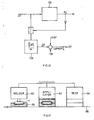
- Fig. 1 shows schematically one principle according to the present invention.
- a container to be leak tested, 1, has an area of its wall 3 which is flexible.
- the principle of the present invention resides in the fact that for leak testing container 1 a biasing member 5 is moved by means of a drive 7 towards and onto the wall of the container 1 and a force detector 9 monitors the reaction force F and generates an electric signal F el according to that force F.
- the force detector 9 is directly coupled to the biasing member 5 and both are driven relative to and onto the flexible area 3 of the wall of the container 1, which latter resides e.g. on a base plate 11.
- the drive 7, which moves one of the biasing member 5, of force detector 9 or of a combined force detector and biasing member 5/9 arrangement with respect to the flexible area 3 of the wall of container 1, is in fact realised as a pneumatic drive.
- Force detector 9 and biasing member 5 are kept stationary in a test chamber 13.
- the test chamber 13 is evacuated, thereby generating a pressure difference ⁇ p between the surrounding of the container 1 and its interior, which is directed from the inside to the outside of the container.
- the flexible wall portion 3 is bent outwards and moved towards and onto the force detector 9, which here and as a preferred embodiment simultaneously acts as biasing member and as force detector.
- biasing container 1 by relatively moving biasing member 5 towards and onto container 1 leads to force detector 9 detecting a rising force F as the container 1 is urged together in the embodiments according to fig. 1 or 2 or is expanded according to the preferred embodiment of fig. 3 .
- fig. 4 as soon as biasing member 5 contacts the wall to of container 1, the reaction force F rises as biasing member 5 is further urged onto the wall of container 1. After a predetermined time t 1 the relative movement of container wall 1 and biasing member 5 is stopped. This leads to a constant reaction force F o , if the container is unleaky and its wall does not further react up to achieving equilibrium of shape.
- a large leak LL is inventively already detected if the biasing member is moved at a predetermined rate or speed towards and onto the container wall and after a predetermined time span as of t 1 - to a predetermined force, as of F o , is not reached.
- such a behaviour of the container is already detected after a time span which is shorter than t 1 - to, so as to become able to stop biasing of the container early enough and before pressing or suctioning a product contained in the container to and into its surrounding.
- a shorter time span t LL - to and after this time span of increased biasing it is checked whether a predetermined threshold force, according to fig. 4 as of F LL , is reached or not. If it is not reached according to the biasing course (b) further biasing is stopped and the heavily leaky container is freed of any bias as quickly as possible.
- the reaction force monitored, F will reach after the predetermined time span of increasing biasing, t 1 - t 0 , the threshold value as of F o as required and leakage behaviour of the container will only be detected afterwards.
- a predetermined time span t 2 - t 1 up to t 2 is installed, during which the system consisting of container 1, biasing member 5 and force detector 9 is left for attaining equilibrium e.g. of the shape of the container.
- the monitored reaction force F At or after reaching t 2 the monitored reaction force F, then prevailing, F 2 , is sampled and stored. After lapse of a further time span t 3 - t 2 up to t 3 again the monitored reaction force F is sampled as F 3 and is compared with reaction force F 2 as was stored. Thus, the difference ⁇ F of F 3 and F 2 is principally evaluated as leak indicative signal.
- Combined biasing member and force detector 9/5 is rigidly mounted within chamber 13 and preferably opposite and adjacent to the area 3 of flexible wall of container 1.
- the force detector 9 generates electrical signal S(F) as a function of the force acting between area 3 and contact area of the biasing/force detector assembly 9/5, which is as schematically shown provided with a surface structure 19 to prevent that surface shutting a leak of area 3 incidentally just happening to be located there, where area 3 is or is going to contact the assembly 9/5.
- the same structuring 19a is preferably provided at the bottom surface of chamber 13.
- the signal S(F) is fed at a time t LL , controlled by timing unit 17 as schematically shown and by switch unit SW 1 , to a comparator unit 21, where at time moment t LL the output signal S(F) is compared with the large leak indicative threshold value S 0 (F LL ) as preset at unit 23.
- switching unit SW 2 Whenever at moment t LL , S 0 (F LL ) is not reached by the force signal S(F), switching unit SW 2 , the input thereof being connected to S(F), is opened disabling via a control unit 25 further biasing e.g. by pump 15. If the threshold value S(F LL ) is at least reached by S(F) at the moment t LL , then signal S(F) is led to a further switching unit SW 3 , where, controlled from timing unit 17 at moment t 2 , the prevailing signal is in fact sampled and stored in storing unit 27. Thus, in unit 27 there is stored a value according to force F 2 of fig. 4 .
- the output of the storing unit 27 is fed to a comparing unit 28, to which, again controlled from timing unit 17, at moment t 3 signal S(F) is additionally fed according to the then prevailing value F 3 .
- comparing unit 28 compares the force value at moment t 2 with the value of that force prevailing at moment t 3 .
- the output ⁇ F of comparator unit 28 is indicative of leak behaviour of container 1 under test beside of a large leak prevailing, which has been previously detected.
- Fig. 6 a most preferred realisation of storing unit 27 and comparator unit 28, schematically shown in fig. 5 , is depicted.
- the output signal of the force detector 9 in assembly 9/5 is input to a conversion unit 121, which comprises, as an input stage, an analogue to digital converter 121a, followed by a digital to analogue converter 121b.
- the output of the converter stage 121 is fed to a difference amplifier unit 123, which additionally receives directly the output signal from force detector 9.
- the output of the difference amplifier 123 according to the comparator unit 28 of fig. 5 , acts on a further amplifier unit 125, the output of which being superimposed at 128 to its input via storage unit 127.
- the input of the storage unit 127 is fed from the output of unit 125.
- a timer unit 129 controls the arrangement.
- the timer unit 129 For storing the signal according to the force value F 2 as of fig. 5 , at time t 2 the timer unit 129 enables a conversion cycle at unit 121, so that a reconverted analogue output signal el o (F 2 ) appears at the analogue output.
- the substantially same signal S(F) from force detector 9 is applied as a signal el (F 2 ) to the second input of unit 123.
- a zero signal should appear at the output unit 125, which signal is stored in the storing unit 127, enabled by the timing unit 129, according to unit 17 of fig. 5 .
- no conversion is triggered at the unit 121, so that there appears at the input of amplifier 123 directly from force detector 9 the signal according to the force value F 3 prevailing at t 3 , and from stage 121 the stored signal according to force value F 2 , which was prevailing at, t 2 .
- the zero offset signal which was stored to unit 127, is now superimposed as an offset compensating signal to the output of unit 123, so that the resulting signal at the output of amplifier unit 125 is zero offset compensated. This allows a very accurate measurement of the force difference ⁇ F as of fig. 4 .
- the volume of the test chamber 13 is not very critical with respect to the volume of the container to be tested.
- a force is evaluated.
- accuracy of measurement is largely dependent on the remaining volume between the wall of the test chamber and that of the container, because leakage will affect the pressure in that intermediate volume the more the smaller than said intermediated volume is selected.
- a wall portion of the container is urged against the force detector. Leakage to the surrounding will affect such force irrespective of the surrounding volume and thus of the relative volume of the test chamber with respect to the container to be tested.
- testing chambers which are minimum in volume with respect to the containers to be tested therein, if biasing is performed by vacuumising according to fig. 3 .
- the level of measuring is set and may be selected.
- the flexible wall portion in its bowing action will reside along a successively larger contact area on the force detector and/or the biasing member with an eye on the embodiment of fig. 3 , establishing a larger biasing pressure difference ⁇ p will lead to an overproportionally rising biasing force F.
- This accords to an amplification of the signal ⁇ F according to fig. 4 to be exploited. This again significantly improves accuracy of the overall measuring system and makes it easy to establish the range of evaluation signals.
- a recess 32 substantially shaped according to pouch 34 (dashed lines) to be tested therein.
- a suctioning line 36 for instance in the base plate 30 there is applied one or more than one suctioning line 36 to be connected to an evacuating pump according to pump 15.
- the top plate 37 as of fig. 8 which is conceived similarly to the bottom plate 30, has a recess 38, which, once the top plate 37 is deposited upon the base plate 30, defines with recess 32 the test chamber or test cavity.
- the bottom surface 40b and the top surface 40a of the two plates 30 and 37 do snugly and vacuum tightly fit and are thereby, if necessary, provided with respective sealing members all around the recesses 32/38.
- a force detector arrangement 42 with a large detection surface 44 fitted to the shape of the test cavity.
- the force detector arrangement 42 preferably operates on the principle of resistance gauge, i.e. pressurising the surface 44 will generate a force according to pressure multiplied by contact surface, which will slightly bend the resistance gauge element, thereby generating the electric signal S(F) according to fig. 5 .
- force detectors operating on different physical principles may clearly be used, thereby preferably force detectors, which operate on minimum mechanical movement.
- a piezo force detector may be used.
- the test cavity as formed by the two recesses 32 and 38 of fig. 7 and 8 for testing pouches is made to snugly fit the shape of a container 1 (a pouch) to be tested therein, it is possible to get additional information especially about large leaks by measuring the electric impedance outside the container under test, which is changed whenever e.g. a liquid content of a leaky container is urged or suctioned out of such container.
- the inner surface of the test cavity may be subdivided in electrically conductive electrodes 44. Every second electrode 44 is connected to one input connector 46 to an impedance measuring unit 48, every electrode in-between to input connector 49.
- Impedance measuring unit 48 may measure AC and/or DC impedance, preferably DC impedance. Thus, whenever the container, as pouch 34, is biased and a liquid or pasty content is pressed into the test cavity, irrespective of large leak measurement according to figs. 4 and 5 as was discussed above, a change in impedance measured at the unit 48 will indicate such a leak, and the output signal of the impedance measuring unit 48 will stop further biasing of the container.
- lines or pipes may be provided abutting in the test cavity and connected to liquid and/or gaseous cleaning media as to a source of air or, and preferably, nitrogen and/or of pressurised liquid flushing medium and further (not shown) a heater may be incorporated into the walls of the test cavity to dry and additionally clean a spoiled test cavity.
- a container 1 to be tested is biased, be it according to the teaching of the fig. 1 or 2 , to which fig. 10 is directed or according to fig. 3 , to which fig. 9 is directed, at least two wall portions of the container, which are disposed one opposite the other, denoted in the figs. 9 and 10 as 51a and 51b, will be firmly pressed onto the biasing member/force detector arrangement or more generically to surfaces.
- a leak to be in such an area of container's wall such a leak might be clogged by such a surface. Therefore and as schematically shown in figs.
- fig. 11a Force versus time courses as measured according to the inventive method and with an inventive apparatus in preferred mode are shown in fig. 11a for very large and large leaks VGL, in fig. 11b for small leaks and for unleaky containers in fig. 11c . These figs. shall be discussed in connection with fig. 12 , which shows a preferred monitoring and control unit.
- the timing unit 201 of fig. 12 initiates at time t lo biasing of a container 1 under test, be it according to the embodiment of fig. 1 or 2 or 3 . According to the embodiment of fig. 3 , thus the timing unit 201 initiates evacuation of the test cavity 13.
- comparator unit 102 is enabled by timer unit 201 at t 10 + ⁇ T.
- the VGL signal preferably stops the biasing cycle, because this would lead just to pressing content of the container under test into the surrounding.
- biasing of the container under test continues up to a further moment of time t 13 .
- the timer unit 201 disables biasing drive, be it the mechanical drive 7 according to the embodiments of the figs. 1 and 2 , or the evacuation pump 15 as of the embodiment of fig. 3 .
- timer unit 201 position of timer unit 201 enables comparator unit 111, to which a further reference value RFGL is led, generated by a reference signal source 113. If at time t 13 the force detected by the force detector has not reached RFGL, then comparator unit 111 generates an output signal GL indicating that the container under test has a large leak GL. Here again, some reactions are taken with respect to further operation of the testing system.
- the timer unit 201 is principally reset because the testing has been completed and the quality of the instantaneously tested container 1 established has been identified. This is schematically shown in fig. 12 by the signal RS 201 . If not reset shortly after t 13 the value S(F) (t 13 ) of the force detected by the force detector is stored in a holding or storing unit 117. The output of the holding or storing unit 117 is led to one input of the difference forming unit 119, whereas the second input of this unit 119 is connected to the output S(F) of the force detector.
- the reference value ⁇ FREF is fed to the comparator unit 125.
- the value of ⁇ FREF may controllably be varied in time and/or a reference value ⁇ R , to which ⁇ FREF is referred to, may also controllably be varied in time.
- a signal FL is generated at unit 125, indicating presence of a fine leak FL in the container 1 under test. This according to the situation as shown in fig. 11b . If the ⁇ F-signal does not reach ⁇ FREF then the container is considered unleaky, as none of the signals VGL, GL and FL has been generated. This accords with fig. 11c .
- This bypass of a testing chamber 13, whereat a container has been identified as heavily or even slightly leaking, is performed so as not to influence further testing results at that chamber and especially not to spoil the vacuum pump 15 connected thereto due to content of the leaky container being suctioned towards and into such pump.
- This bypass chamber is reconditioned during further testing cycles at the other chambers after the leaky container having been removed.
- Reconditioning may be done by heating that chamber 13, flushing it by a liquid and/or a gas, preferably nitrogen, especially by a heated gas.
- the force values measured at the tight containers are slightly different and define a statistic distribution as shown in fig. 13 .
- the value of RFGL as used at the comparator 111 of fig. 12 or as used according to the figs. 11a to 11c is found in that an offset value ⁇ RFGL is subtracted from (RFGL) m .
- temperatures and manufacturing tolerances of such containers may vary. Such parameters may slowly change and may vary (RFGL) m .
- the actual output signal of the force detector is entered into an averaging unit 130 as shown in fig. 14 , wherein the last m values of actual force of not heavily leaky containers are averaged.
- the output average result signal accords with (RFGL) m of fig. 13 , now varies in time e.g. due to varying manufacturing parameters of one and the same type of containers.
- the result of this operation is a dynamically varying reference value RFGL, which is applied to comparator unit 111 of fig. 12 .
- This dynamically varying reference value RFGL is shown in fig. 15 qualitatively, starting from an initial setting as e.g. found as was explained with the help of measurements at unleaky test containers.
- FIG. 17 there is shown an inline plant, wherein generically assembling and testing of containers is done inline.
- pouches are first welded at a welding station 60 in a base plate 30 as shown in fig. 7 used as carrier and support for assembling.
- the carrier formed by plate 30 is moved to an applicator station, where the top plate 37 as of fig. 8 is assembled upon the bottom plate 30.
- the thus sealingly closed test cavity is moved and applied to a test station 64, where the inventive test is performed.
- the system of welder 60 and/or applicator 62 and/or tester 64 may thereby be stationary with respect to a conveyor 66 for base plate 30. Nevertheless, and depending on time requested for a certain operation, especially tester 64 may be moved together with conveyor 66 for a predetermined time, so as to become independent of speed of conveyor 66.
- a leak testing technique which is much less critical in achieving the same accuracy as with leak testing techniques evaluating pressure measurements.
- Biasing containers according to the present invention is much simpler than establishing a perfect vacuum around such container and measuring a biasing force considerably easier than accurately measuring the time development of a vacuum pressure surrounding the container.
- vacuum measurement much more unknown and uncontrollable parameters may affect the measured entities, namely vacuum pressure, than in the here inventively exploited force measurement.
- setting of the measuring level in vacuum measurement technique greatly influences the expenditure for vacuum pumps, varying and setting a biasing force is of much less effort.
- the inventive method and apparatus are especially suited for testing pouches, but clearly may be used for testing all kinds of containers up to big tanks as long as a wall portion thereof is flexibly bendable.
- the present invention may be realised at inline plants with a multitude of testing stations, e.g. arranged on a carousel with a very high throughput.
Landscapes
- Physics & Mathematics (AREA)
- General Physics & Mathematics (AREA)
- Examining Or Testing Airtightness (AREA)
- Closing Of Containers (AREA)
Priority Applications (2)
| Application Number | Priority Date | Filing Date | Title |
|---|---|---|---|
| DK09150253.4T DK2040054T3 (da) | 2000-09-26 | 2000-09-26 | Fremgangsmåde og apparat til tæthedsprøvning af lukkede beholdere |
| EP09150253.4A EP2040054B1 (en) | 2000-09-26 | 2000-09-26 | Method and apparatus for leak testing closed containers |
Applications Claiming Priority (1)
| Application Number | Priority Date | Filing Date | Title |
|---|---|---|---|
| PCT/CH2000/000526 WO2000073760A2 (en) | 2000-09-26 | 2000-09-26 | Method and apparatus for leak testing closed containers |
Related Child Applications (1)
| Application Number | Title | Priority Date | Filing Date |
|---|---|---|---|
| EP09150253.4A Division EP2040054B1 (en) | 2000-09-26 | 2000-09-26 | Method and apparatus for leak testing closed containers |
Publications (2)
| Publication Number | Publication Date |
|---|---|
| EP1320738A2 EP1320738A2 (en) | 2003-06-25 |
| EP1320738B1 true EP1320738B1 (en) | 2009-03-18 |
Family
ID=4358139
Family Applications (2)
| Application Number | Title | Priority Date | Filing Date |
|---|---|---|---|
| EP00960280A Expired - Lifetime EP1320738B1 (en) | 2000-09-26 | 2000-09-26 | Method and apparatus for leak testing closed containers |
| EP09150253.4A Expired - Lifetime EP2040054B1 (en) | 2000-09-26 | 2000-09-26 | Method and apparatus for leak testing closed containers |
Family Applications After (1)
| Application Number | Title | Priority Date | Filing Date |
|---|---|---|---|
| EP09150253.4A Expired - Lifetime EP2040054B1 (en) | 2000-09-26 | 2000-09-26 | Method and apparatus for leak testing closed containers |
Country Status (13)
| Country | Link |
|---|---|
| US (2) | US6439032B1 (enExample) |
| EP (2) | EP1320738B1 (enExample) |
| JP (1) | JP4854891B2 (enExample) |
| CN (1) | CN100342225C (enExample) |
| AT (1) | ATE426152T1 (enExample) |
| AU (4) | AU2000272661C1 (enExample) |
| DE (1) | DE60041835D1 (enExample) |
| DK (2) | DK1320738T3 (enExample) |
| ES (2) | ES2459665T3 (enExample) |
| NO (1) | NO20031242D0 (enExample) |
| PT (2) | PT2040054E (enExample) |
| RU (2) | RU2243524C1 (enExample) |
| WO (1) | WO2000073760A2 (enExample) |
Families Citing this family (44)
| Publication number | Priority date | Publication date | Assignee | Title |
|---|---|---|---|---|
| US6082184A (en) * | 1997-05-27 | 2000-07-04 | Martin Lehmann | Method for leak testing and leak testing apparatus |
| DE60041835D1 (de) * | 2000-09-26 | 2009-04-30 | Martin Lehmann | Verfahren und vorrichtung zur dichtheitsprüfung geschlossener behälter |
| US6840087B2 (en) * | 2000-09-26 | 2005-01-11 | Martin Lehmann | Method and apparatus for leak testing closed containers |
| ITBO20010371A1 (it) * | 2001-06-12 | 2002-12-12 | Ima Spa | Metodo per la verifica dell'integrita' di confezioni, in particolare monodose, e stazione che attua tale metodo |
| EP1469296A1 (en) * | 2003-04-14 | 2004-10-20 | Lorenzo Campanini | Process and apparatus for checking sealor tightness of a package made of flexible or semirigid material |
| EP1515364B1 (en) | 2003-09-15 | 2016-04-13 | Nuvotronics, LLC | Device package and methods for the fabrication and testing thereof |
| US7947013B2 (en) * | 2004-01-09 | 2011-05-24 | G.I. View Ltd. | Pressure-propelled system for body lumen |
| US8419678B2 (en) | 2004-01-09 | 2013-04-16 | G.I. View Ltd. | Pressure-propelled system for body lumen |
| JP4353860B2 (ja) * | 2004-06-24 | 2009-10-28 | 株式会社エヌテック | 容器の検査方法及び装置 |
| US7862875B2 (en) * | 2004-10-04 | 2011-01-04 | Trico Corporation | Flinger disc |
| CN101115437A (zh) * | 2005-01-06 | 2008-01-30 | G.I.视频有限公司 | 导向元件上的胃肠工具 |
| CN101541227B (zh) * | 2005-02-10 | 2013-06-05 | G.I.视频有限公司 | 用于带导向元件的胃肠工具的前进技术 |
| US8430809B2 (en) * | 2005-08-01 | 2013-04-30 | G. I View Ltd. | Capsule for use in small intestine |
| US20090182197A1 (en) * | 2005-08-01 | 2009-07-16 | G.I. View Ltd. | Tools for use in small intestine |
| US9241614B2 (en) * | 2005-08-01 | 2016-01-26 | G.I. View Ltd. | Tools for use in esophagus |
| CN103148986B (zh) * | 2005-09-09 | 2016-03-02 | 马丁·莱曼 | 用于制造不渗漏封闭容器的方法和渗漏测试设备 |
| RU2370743C1 (ru) * | 2005-09-09 | 2009-10-20 | Мартин Леманн | Способы изготовления герметично закрытых контейнеров и устройство для испытания на герметичность |
| US7380440B2 (en) * | 2005-09-09 | 2008-06-03 | Martin Lehmann | Methods for manufacturing unleaky closed containers and leak testing apparatus |
| AU2005255063B2 (en) * | 2005-09-09 | 2011-12-15 | Wilco Ag | Methods for manufacturing unleaky closed containers and leak testing apparatus |
| KR101489989B1 (ko) * | 2008-07-30 | 2015-02-04 | 지.아이. 뷰 리미티드 | 기동성이 강화된 시스템 및 그에 대한 방법 |
| EP2375961B1 (en) | 2008-11-03 | 2019-01-09 | G.I. View Ltd. | Remote pressure sensing system and method thereof |
| RU2390742C1 (ru) * | 2008-11-10 | 2010-05-27 | Российская Федерация, от имени которой выступает Государственная корпорация по атомной энергии "Росатом" | Способ контроля контейнеров с хранящимися в них материалами |
| DK2502043T3 (en) * | 2009-11-20 | 2018-04-23 | Packaging Tech & Inspection Llc | Rest vacuum state of a method and system for vacuum degradation leakage testing |
| US9200993B2 (en) | 2011-11-01 | 2015-12-01 | Teledyne Instruments, Inc. | Flexible container inspection |
| US20150316441A1 (en) * | 2012-12-05 | 2015-11-05 | University Of Florida Research Foundation, Inc. | Method and apparatus for testing quality of seal and package integrity |
| US9561323B2 (en) * | 2013-03-14 | 2017-02-07 | Fresenius Medical Care Holdings, Inc. | Medical fluid cassette leak detection methods and devices |
| ITBO20130128A1 (it) * | 2013-03-26 | 2014-09-27 | Bonfiglioli Engineering S P A | Metodo ed apparato per la verifica di corpi siringa. |
| HUE034635T2 (en) * | 2013-03-27 | 2018-02-28 | Wilco Ag | A method for checking and / or testing devices in a row and equipment for performing such a procedure |
| KR102377615B1 (ko) * | 2013-12-10 | 2022-03-22 | 아벡, 아이엔씨. | 장치 및 사용 방법 |
| CN104977142A (zh) * | 2014-04-09 | 2015-10-14 | 江苏神通阀门股份有限公司 | 一种密闭阀寿命试验装置 |
| CN104111150B (zh) * | 2014-06-30 | 2017-10-24 | 苏州大学 | 一种容器检测口的密封性检测装置和检测方法 |
| CN105444927A (zh) * | 2015-11-25 | 2016-03-30 | 广州坚诺机械设备有限公司 | 一种基于挤压的容器压力快速无损检测设备及方法 |
| US10067027B2 (en) * | 2016-03-04 | 2018-09-04 | Robert Bosch Gmbh | Test methodology to reduce false rejections and increase number of containers tested for tightness |
| CN106370365B (zh) * | 2016-08-16 | 2019-07-02 | 中国科学院化学研究所 | 液体封装装置的检漏方法 |
| US10319654B1 (en) | 2017-12-01 | 2019-06-11 | Cubic Corporation | Integrated chip scale packages |
| CN108150629A (zh) * | 2017-12-29 | 2018-06-12 | 盛瑞传动股份有限公司 | 变矩器壳体总成及其气密测量工艺 |
| CN108851162B (zh) * | 2018-03-29 | 2021-06-01 | 保定市三川电气有限责任公司 | 物料真空回潮的控制方法及系统、回潮机 |
| ES2935309T3 (es) | 2019-10-17 | 2023-03-03 | Delta Eng Bvba | Probador de fugas |
| IT201900021456A1 (it) | 2019-11-18 | 2021-05-18 | Ceccarani Eng S R L | Dispositivo di controllo della tenuta ermetica di contenitori flessibili chiusi |
| DE102019135223A1 (de) * | 2019-12-19 | 2021-06-24 | Krones Ag | Verfahren und Vorrichtung zum Erkennen der Strukturintegrität eines zu verschließenden Behälters |
| US11867591B2 (en) | 2020-11-12 | 2024-01-09 | Lockheed Martin Corporation | Backup oxygen supply bottle pressure measurement and leak test tool |
| US11692672B2 (en) | 2020-12-17 | 2023-07-04 | Lockheed Martin Corporation | Pressure relief shipping adapter for a bottle head assembly |
| US20250129894A1 (en) * | 2023-10-18 | 2025-04-24 | Lockheed Martin Corporation | Pressure relief shipping adapter |
| IT202300026271A1 (it) * | 2023-12-07 | 2025-06-07 | S A T S R L | Procedimento ed apparato per il controllo della presenza di uno o più fori in un articolo per il contenimento di un materiale biologico o farmaceutico |
Citations (1)
| Publication number | Priority date | Publication date | Assignee | Title |
|---|---|---|---|---|
| EP0619015B1 (de) * | 1992-08-27 | 1997-11-19 | Martin Lehmann | Verfahren zur prüfung eines behältnisses, prüfanordnung, verwendung |
Family Cites Families (34)
| Publication number | Priority date | Publication date | Assignee | Title |
|---|---|---|---|---|
| US2784373A (en) * | 1953-03-02 | 1957-03-05 | Nat Res Corp | High-vacuum device |
| US3837215A (en) * | 1973-05-21 | 1974-09-24 | T Massage | Method and apparatus for testing sealed containers |
| US4107997A (en) * | 1975-09-15 | 1978-08-22 | Advanced Patent Technology, Incorporated | Alloy sensor |
| FR2351400A1 (fr) * | 1976-05-10 | 1977-12-09 | Lesieur Cotelle | Procede et appareil de controle et de selection de conditionnements comportant des emballages scelles |
| GB2059381A (en) * | 1979-10-06 | 1981-04-23 | Danepak Ltd | Leak detecting of vacuum sealed packages |
| JPS5719638A (en) * | 1980-07-11 | 1982-02-01 | Citizen Watch Co Ltd | Inspection for air leak of wrist watch |
| US4449396A (en) * | 1982-03-01 | 1984-05-22 | Carrier Corporation | Probe for measuring electrical conductance |
| US4459843A (en) * | 1982-07-06 | 1984-07-17 | Durham La Moyne W | Apparatus and method for testing containers |
| JPS59157537A (ja) * | 1983-02-28 | 1984-09-06 | Toyo Seikan Kaisha Ltd | 缶内圧検出方法及びその装置 |
| US4955226A (en) * | 1984-12-26 | 1990-09-11 | Frito-Lay, Inc. | Method and apparatus for automatically detecting the presence of holes in filled and sealed packed plastic bags |
| GB8506443D0 (en) * | 1985-03-13 | 1985-04-17 | Bishopbarn Ltd | Testing leaks in packages |
| US4715215A (en) * | 1985-04-25 | 1987-12-29 | The Aro Corporation | Method and apparatus for testing the fluid-tight sealed integrity of a hermetically-sealed package in a rapidly-stabilized environment |
| US4771630A (en) * | 1985-12-20 | 1988-09-20 | Warner-Lambert Company | Method and apparatus for testing hermetic seal integrity of sealed packages and containers |
| US4756184A (en) * | 1987-03-12 | 1988-07-12 | General Mills, Inc. | Apparatus and method for seal testing flexible containers |
| DE3716095C1 (de) * | 1987-05-14 | 1988-09-08 | Hamba Maschf | Becherfuellwerk fuer Nahrungs- und Genussmittel,insbesondere fuer Molkereiprodukte |
| US4862732A (en) * | 1987-10-19 | 1989-09-05 | Benthos, Inc. | Leak testing |
| US4747299A (en) * | 1987-10-28 | 1988-05-31 | The Aro Corporation | Method of testing a package seal |
| SU1619085A1 (ru) * | 1988-02-04 | 1991-01-07 | Предприятие П/Я М-5068 | Способ контрол герметичности изделий |
| JPH0257533A (ja) * | 1988-08-22 | 1990-02-27 | Taiyo Fishery Co Ltd | 密閉容器のリーク検査方法 |
| US5029463A (en) * | 1990-03-01 | 1991-07-09 | American Air Liquide | Leak detection device for in-line measurement of package integrity |
| US5195360A (en) * | 1990-10-12 | 1993-03-23 | General Mills, Inc. | Apparatus and methods for testing double packages |
| GB9204137D0 (en) * | 1992-02-26 | 1992-04-08 | Fenlon Christopher | Sealed package integrity testing machine |
| US5915270A (en) | 1992-08-27 | 1999-06-22 | Lehmann; Martin | Method for testing containers, use of the method, and a testing device |
| US5528925A (en) * | 1993-01-19 | 1996-06-25 | Luigino's, Inc. | Method and apparatus for testing the seal between a container and a flexible lid |
| US5533385A (en) * | 1995-02-06 | 1996-07-09 | Frievalt; William | Package seal integrity testing device and method of operation thereof |
| CA2230214A1 (en) * | 1995-08-25 | 1997-03-06 | Christopher Fenlon | Method of and apparatus for testing for leaks in a package |
| GB9601014D0 (en) | 1996-01-18 | 1996-03-20 | Testamatic Ltd | Package tester |
| US5767392A (en) * | 1996-08-28 | 1998-06-16 | The Clorox Company | Method and apparatus for leak testing containers having a flexible side wall structure |
| EP0791814A3 (en) * | 1997-05-26 | 1997-11-26 | Martin Lehmann | Method for leak testing and leak testing apparatus |
| US6082184A (en) * | 1997-05-27 | 2000-07-04 | Martin Lehmann | Method for leak testing and leak testing apparatus |
| EP0786655B1 (de) * | 1997-05-07 | 2002-07-24 | Martin Lehmann | Verfahren zur Dichtheitsprüfung geschlossener Behälter, Prüfkammer, Prüfanordnung und Prüfanlage hierfür |
| JP2000088694A (ja) * | 1998-09-16 | 2000-03-31 | Ishida Co Ltd | 密封容器の密封性検査装置 |
| JP2000131182A (ja) * | 1998-10-22 | 2000-05-12 | Nikka Kensa Kikai Kk | 密封容器の密封不良検査方法および装置 |
| DE60041835D1 (de) * | 2000-09-26 | 2009-04-30 | Martin Lehmann | Verfahren und vorrichtung zur dichtheitsprüfung geschlossener behälter |
-
2000
- 2000-09-26 DE DE60041835T patent/DE60041835D1/de not_active Expired - Lifetime
- 2000-09-26 US US09/669,669 patent/US6439032B1/en not_active Expired - Lifetime
- 2000-09-26 DK DK00960280T patent/DK1320738T3/da active
- 2000-09-26 DK DK09150253.4T patent/DK2040054T3/da active
- 2000-09-26 PT PT91502534T patent/PT2040054E/pt unknown
- 2000-09-26 CN CNB008199108A patent/CN100342225C/zh not_active Expired - Fee Related
- 2000-09-26 ES ES09150253.4T patent/ES2459665T3/es not_active Expired - Lifetime
- 2000-09-26 RU RU2003112218/28A patent/RU2243524C1/ru not_active IP Right Cessation
- 2000-09-26 ES ES00960280T patent/ES2323749T3/es not_active Expired - Lifetime
- 2000-09-26 AT AT00960280T patent/ATE426152T1/de active
- 2000-09-26 WO PCT/CH2000/000526 patent/WO2000073760A2/en not_active Ceased
- 2000-09-26 AU AU2000272661A patent/AU2000272661C1/en not_active Ceased
- 2000-09-26 AU AU7266100A patent/AU7266100A/xx active Pending
- 2000-09-26 EP EP00960280A patent/EP1320738B1/en not_active Expired - Lifetime
- 2000-09-26 JP JP2001500835A patent/JP4854891B2/ja not_active Expired - Lifetime
- 2000-09-26 EP EP09150253.4A patent/EP2040054B1/en not_active Expired - Lifetime
- 2000-09-26 PT PT00960280T patent/PT1320738E/pt unknown
-
2002
- 2002-07-30 US US10/207,148 patent/US6557395B2/en not_active Expired - Lifetime
-
2003
- 2003-03-18 NO NO20031242A patent/NO20031242D0/no not_active Application Discontinuation
-
2005
- 2005-11-04 AU AU2005229712A patent/AU2005229712C1/en not_active Ceased
-
2008
- 2008-08-11 AU AU2008203815A patent/AU2008203815B9/en not_active Ceased
- 2008-08-14 RU RU2008133456/28A patent/RU2389006C1/ru not_active IP Right Cessation
Patent Citations (1)
| Publication number | Priority date | Publication date | Assignee | Title |
|---|---|---|---|---|
| EP0619015B1 (de) * | 1992-08-27 | 1997-11-19 | Martin Lehmann | Verfahren zur prüfung eines behältnisses, prüfanordnung, verwendung |
Also Published As
Similar Documents
| Publication | Publication Date | Title |
|---|---|---|
| EP1320738B1 (en) | Method and apparatus for leak testing closed containers | |
| AU2000272661A1 (en) | Method and apparatus for leak testing closed containers | |
| US7313944B2 (en) | Method and apparatus for leak testing closed containers | |
| US7584650B2 (en) | Methods for manufacturing unleaky closed containers and leak testing apparatus | |
| RU2492440C2 (ru) | Способ испытания закрытого контейнера на герметичность, способ изготовления герметично закрытых контейнеров и устройство для испытания на герметичность | |
| RU2344396C2 (ru) | Способ испытания на герметичность закрытых контейнеров и устройство для его осуществления | |
| CN101126673A (zh) | 对封闭容器进行渗漏试验的方法和仪器 | |
| CN101126672A (zh) | 对封闭容器进行渗漏试验的方法和仪器 | |
| CN101126670A (zh) | 对封闭容器进行渗漏试验的方法和仪器 | |
| CN101126671A (zh) | 对封闭容器进行渗漏试验的方法和仪器 | |
| NZ566115A (en) | Methods for manufacturing unleaky closed containers and leak testing apparatus | |
| KR20080045274A (ko) | 비누설 밀폐 용기 제조 방법 및 누설 검사 장치 |
Legal Events
| Date | Code | Title | Description |
|---|---|---|---|
| PUAI | Public reference made under article 153(3) epc to a published international application that has entered the european phase |
Free format text: ORIGINAL CODE: 0009012 |
|
| 17P | Request for examination filed |
Effective date: 20030111 |
|
| AK | Designated contracting states |
Designated state(s): AT BE CH CY DE DK ES FI FR GB GR IE IT LI LU MC NL PT SE |
|
| AX | Request for extension of the european patent |
Extension state: AL LT LV MK RO SI |
|
| GRAP | Despatch of communication of intention to grant a patent |
Free format text: ORIGINAL CODE: EPIDOSNIGR1 |
|
| RAP1 | Party data changed (applicant data changed or rights of an application transferred) |
Owner name: LEHMANN, MARTIN |
|
| RIN1 | Information on inventor provided before grant (corrected) |
Inventor name: LEHMANN, MARTIN |
|
| GRAS | Grant fee paid |
Free format text: ORIGINAL CODE: EPIDOSNIGR3 |
|
| GRAA | (expected) grant |
Free format text: ORIGINAL CODE: 0009210 |
|
| AK | Designated contracting states |
Kind code of ref document: B1 Designated state(s): AT BE CH CY DE DK ES FI FR GB GR IE IT LI LU MC NL PT SE |
|
| REG | Reference to a national code |
Ref country code: GB Ref legal event code: FG4D |
|
| REG | Reference to a national code |
Ref country code: CH Ref legal event code: EP |
|
| REG | Reference to a national code |
Ref country code: CH Ref legal event code: NV Representative=s name: TROESCH SCHEIDEGGER WERNER AG |
|
| REG | Reference to a national code |
Ref country code: IE Ref legal event code: FG4D |
|
| REF | Corresponds to: |
Ref document number: 60041835 Country of ref document: DE Date of ref document: 20090430 Kind code of ref document: P |
|
| REG | Reference to a national code |
Ref country code: PT Ref legal event code: SC4A Free format text: AVAILABILITY OF NATIONAL TRANSLATION Effective date: 20090514 |
|
| REG | Reference to a national code |
Ref country code: GR Ref legal event code: EP Ref document number: 20090401325 Country of ref document: GR |
|
| REG | Reference to a national code |
Ref country code: DK Ref legal event code: T3 |
|
| REG | Reference to a national code |
Ref country code: SE Ref legal event code: TRGR |
|
| REG | Reference to a national code |
Ref country code: ES Ref legal event code: FG2A Ref document number: 2323749 Country of ref document: ES Kind code of ref document: T3 |
|
| PLBE | No opposition filed within time limit |
Free format text: ORIGINAL CODE: 0009261 |
|
| STAA | Information on the status of an ep patent application or granted ep patent |
Free format text: STATUS: NO OPPOSITION FILED WITHIN TIME LIMIT |
|
| 26N | No opposition filed |
Effective date: 20091221 |
|
| PG25 | Lapsed in a contracting state [announced via postgrant information from national office to epo] |
Ref country code: MC Free format text: LAPSE BECAUSE OF NON-PAYMENT OF DUE FEES Effective date: 20090930 |
|
| REG | Reference to a national code |
Ref country code: HK Ref legal event code: WD Ref document number: 1058232 Country of ref document: HK |
|
| PGFP | Annual fee paid to national office [announced via postgrant information from national office to epo] |
Ref country code: GR Payment date: 20090827 Year of fee payment: 10 |
|
| PG25 | Lapsed in a contracting state [announced via postgrant information from national office to epo] |
Ref country code: LU Free format text: LAPSE BECAUSE OF NON-PAYMENT OF DUE FEES Effective date: 20090926 |
|
| PG25 | Lapsed in a contracting state [announced via postgrant information from national office to epo] |
Ref country code: GR Free format text: LAPSE BECAUSE OF NON-PAYMENT OF DUE FEES Effective date: 20110404 |
|
| PG25 | Lapsed in a contracting state [announced via postgrant information from national office to epo] |
Ref country code: CY Free format text: LAPSE BECAUSE OF FAILURE TO SUBMIT A TRANSLATION OF THE DESCRIPTION OR TO PAY THE FEE WITHIN THE PRESCRIBED TIME-LIMIT Effective date: 20090318 |
|
| REG | Reference to a national code |
Ref country code: CH Ref legal event code: PUE Owner name: WILCO AG, CH Free format text: FORMER OWNER: LEHMANN, MARTIN, CH |
|
| REG | Reference to a national code |
Ref country code: DE Ref legal event code: R082 Ref document number: 60041835 Country of ref document: DE Representative=s name: STREHL, SCHUEBEL-HOPF & PARTNER, DE |
|
| REG | Reference to a national code |
Ref country code: DE Ref legal event code: R081 Ref document number: 60041835 Country of ref document: DE Owner name: WILCO AG, CH Free format text: FORMER OWNER: LEHMANN, MARTIN, WOHLEN, CH Effective date: 20130206 Ref country code: DE Ref legal event code: R082 Ref document number: 60041835 Country of ref document: DE Representative=s name: STREHL, SCHUEBEL-HOPF & PARTNER, DE Effective date: 20130206 Ref country code: DE Ref legal event code: R082 Ref document number: 60041835 Country of ref document: DE Representative=s name: PATENTANWAELTE STREHL, SCHUEBEL-HOPF & PARTNER, DE Effective date: 20130206 Ref country code: DE Ref legal event code: R082 Ref document number: 60041835 Country of ref document: DE Representative=s name: STREHL SCHUEBEL-HOPF & PARTNER MBB PATENTANWAE, DE Effective date: 20130206 |
|
| REG | Reference to a national code |
Ref country code: PT Ref legal event code: PC4A Owner name: WILCO AG, CH Effective date: 20130409 |
|
| REG | Reference to a national code |
Ref country code: NL Ref legal event code: SD Effective date: 20130605 |
|
| REG | Reference to a national code |
Ref country code: FR Ref legal event code: TP Owner name: WILCO AG, CH Effective date: 20130523 |
|
| REG | Reference to a national code |
Ref country code: AT Ref legal event code: PC Ref document number: 426152 Country of ref document: AT Kind code of ref document: T Owner name: WILCO AG, CH Effective date: 20130719 |
|
| REG | Reference to a national code |
Ref country code: ES Ref legal event code: PC2A Owner name: WILCO AG Effective date: 20131031 |
|
| REG | Reference to a national code |
Ref country code: GB Ref legal event code: 732E Free format text: REGISTERED BETWEEN 20131107 AND 20131113 |
|
| REG | Reference to a national code |
Ref country code: FR Ref legal event code: PLFP Year of fee payment: 16 |
|
| PGFP | Annual fee paid to national office [announced via postgrant information from national office to epo] |
Ref country code: CH Payment date: 20150924 Year of fee payment: 16 Ref country code: PT Payment date: 20150922 Year of fee payment: 16 Ref country code: FI Payment date: 20150909 Year of fee payment: 16 Ref country code: GB Payment date: 20150923 Year of fee payment: 16 Ref country code: IE Payment date: 20150909 Year of fee payment: 16 Ref country code: ES Payment date: 20150810 Year of fee payment: 16 |
|
| PGFP | Annual fee paid to national office [announced via postgrant information from national office to epo] |
Ref country code: FR Payment date: 20150811 Year of fee payment: 16 Ref country code: AT Payment date: 20150825 Year of fee payment: 16 Ref country code: BE Payment date: 20150911 Year of fee payment: 16 Ref country code: SE Payment date: 20150911 Year of fee payment: 16 |
|
| PGFP | Annual fee paid to national office [announced via postgrant information from national office to epo] |
Ref country code: DK Payment date: 20150910 Year of fee payment: 16 |
|
| PGFP | Annual fee paid to national office [announced via postgrant information from national office to epo] |
Ref country code: IT Payment date: 20150925 Year of fee payment: 16 |
|
| PGFP | Annual fee paid to national office [announced via postgrant information from national office to epo] |
Ref country code: NL Payment date: 20150909 Year of fee payment: 16 |
|
| PG25 | Lapsed in a contracting state [announced via postgrant information from national office to epo] |
Ref country code: BE Free format text: LAPSE BECAUSE OF NON-PAYMENT OF DUE FEES Effective date: 20160930 |
|
| REG | Reference to a national code |
Ref country code: DK Ref legal event code: EBP Effective date: 20160930 |
|
| PG25 | Lapsed in a contracting state [announced via postgrant information from national office to epo] |
Ref country code: SE Free format text: LAPSE BECAUSE OF NON-PAYMENT OF DUE FEES Effective date: 20160927 Ref country code: FI Free format text: LAPSE BECAUSE OF NON-PAYMENT OF DUE FEES Effective date: 20160926 |
|
| REG | Reference to a national code |
Ref country code: CH Ref legal event code: PL |
|
| REG | Reference to a national code |
Ref country code: SE Ref legal event code: EUG |
|
| REG | Reference to a national code |
Ref country code: NL Ref legal event code: MM Effective date: 20161001 |
|
| REG | Reference to a national code |
Ref country code: AT Ref legal event code: MM01 Ref document number: 426152 Country of ref document: AT Kind code of ref document: T Effective date: 20160926 |
|
| GBPC | Gb: european patent ceased through non-payment of renewal fee |
Effective date: 20160926 |
|
| PG25 | Lapsed in a contracting state [announced via postgrant information from national office to epo] |
Ref country code: PT Free format text: LAPSE BECAUSE OF NON-PAYMENT OF DUE FEES Effective date: 20170327 |
|
| REG | Reference to a national code |
Ref country code: IE Ref legal event code: MM4A |
|
| PG25 | Lapsed in a contracting state [announced via postgrant information from national office to epo] |
Ref country code: NL Free format text: LAPSE BECAUSE OF NON-PAYMENT OF DUE FEES Effective date: 20161001 |
|
| REG | Reference to a national code |
Ref country code: FR Ref legal event code: ST Effective date: 20170531 |
|
| PG25 | Lapsed in a contracting state [announced via postgrant information from national office to epo] |
Ref country code: CH Free format text: LAPSE BECAUSE OF NON-PAYMENT OF DUE FEES Effective date: 20160930 Ref country code: IE Free format text: LAPSE BECAUSE OF NON-PAYMENT OF DUE FEES Effective date: 20160926 Ref country code: GB Free format text: LAPSE BECAUSE OF NON-PAYMENT OF DUE FEES Effective date: 20160926 Ref country code: LI Free format text: LAPSE BECAUSE OF NON-PAYMENT OF DUE FEES Effective date: 20160930 Ref country code: FR Free format text: LAPSE BECAUSE OF NON-PAYMENT OF DUE FEES Effective date: 20160930 |
|
| PG25 | Lapsed in a contracting state [announced via postgrant information from national office to epo] |
Ref country code: IT Free format text: LAPSE BECAUSE OF NON-PAYMENT OF DUE FEES Effective date: 20160926 Ref country code: AT Free format text: LAPSE BECAUSE OF NON-PAYMENT OF DUE FEES Effective date: 20160926 |
|
| REG | Reference to a national code |
Ref country code: BE Ref legal event code: MM Effective date: 20160930 |
|
| PG25 | Lapsed in a contracting state [announced via postgrant information from national office to epo] |
Ref country code: DK Free format text: LAPSE BECAUSE OF NON-PAYMENT OF DUE FEES Effective date: 20160930 |
|
| PG25 | Lapsed in a contracting state [announced via postgrant information from national office to epo] |
Ref country code: ES Free format text: LAPSE BECAUSE OF NON-PAYMENT OF DUE FEES Effective date: 20160927 |
|
| REG | Reference to a national code |
Ref country code: ES Ref legal event code: FD2A Effective date: 20181120 |
|
| PGFP | Annual fee paid to national office [announced via postgrant information from national office to epo] |
Ref country code: DE Payment date: 20190910 Year of fee payment: 20 |
|
| REG | Reference to a national code |
Ref country code: DE Ref legal event code: R071 Ref document number: 60041835 Country of ref document: DE |