EP1319810A1 - Brennkraftmaschine mit Kolbenkühlung und Schmierung eines Ventiltriebes - Google Patents
Brennkraftmaschine mit Kolbenkühlung und Schmierung eines Ventiltriebes Download PDFInfo
- Publication number
- EP1319810A1 EP1319810A1 EP02027805A EP02027805A EP1319810A1 EP 1319810 A1 EP1319810 A1 EP 1319810A1 EP 02027805 A EP02027805 A EP 02027805A EP 02027805 A EP02027805 A EP 02027805A EP 1319810 A1 EP1319810 A1 EP 1319810A1
- Authority
- EP
- European Patent Office
- Prior art keywords
- oil
- bores
- lubricating
- nozzles
- spray nozzles
- Prior art date
- Legal status (The legal status is an assumption and is not a legal conclusion. Google has not performed a legal analysis and makes no representation as to the accuracy of the status listed.)
- Granted
Links
Images

Classifications
-
- F—MECHANICAL ENGINEERING; LIGHTING; HEATING; WEAPONS; BLASTING
- F01—MACHINES OR ENGINES IN GENERAL; ENGINE PLANTS IN GENERAL; STEAM ENGINES
- F01M—LUBRICATING OF MACHINES OR ENGINES IN GENERAL; LUBRICATING INTERNAL COMBUSTION ENGINES; CRANKCASE VENTILATING
- F01M9/00—Lubrication means having pertinent characteristics not provided for in, or of interest apart from, groups F01M1/00 - F01M7/00
- F01M9/10—Lubrication of valve gear or auxiliaries
- F01M9/104—Lubrication of valve gear or auxiliaries of tappets
-
- F—MECHANICAL ENGINEERING; LIGHTING; HEATING; WEAPONS; BLASTING
- F01—MACHINES OR ENGINES IN GENERAL; ENGINE PLANTS IN GENERAL; STEAM ENGINES
- F01M—LUBRICATING OF MACHINES OR ENGINES IN GENERAL; LUBRICATING INTERNAL COMBUSTION ENGINES; CRANKCASE VENTILATING
- F01M1/00—Pressure lubrication
- F01M1/08—Lubricating systems characterised by the provision therein of lubricant jetting means
-
- F—MECHANICAL ENGINEERING; LIGHTING; HEATING; WEAPONS; BLASTING
- F01—MACHINES OR ENGINES IN GENERAL; ENGINE PLANTS IN GENERAL; STEAM ENGINES
- F01M—LUBRICATING OF MACHINES OR ENGINES IN GENERAL; LUBRICATING INTERNAL COMBUSTION ENGINES; CRANKCASE VENTILATING
- F01M11/00—Component parts, details or accessories, not provided for in, or of interest apart from, groups F01M1/00 - F01M9/00
- F01M11/02—Arrangements of lubricant conduits
Definitions
- the invention relates to an internal combustion engine according to the generic term of claim 1.
- Oil spray nozzles for cooling piston crowns.
- the Oil spray nozzles are positioned on the inside of a crankcase and via an axially parallel to the crankshaft penetrating the crankcase Oil channel supplied with lubricating oil. About this oil channel too the lubricating nozzles for the lubrication of the valve lifters.
- the oil spray nozzles and the lubrication nozzles are arranged in separate holes which is natural requires a large number of holes. To be flawless Ensuring cooling of the piston crowns is an exact positioning of the oil spray nozzles indispensable, which creates difficulties during assembly. Further provides the variety of holes for the oil spray nozzles and the lubricating nozzles represents a high manufacturing effort.
- the invention has for its object the manufacturing cost for the attachment to keep the oil spray nozzles and the lubricating nozzles as low as possible and without affecting the functionality of these parts.
- the oil spray nozzles used in the first holes are attached using a tab and only one screw both oil-tight and against twisting secured.
- Figure 1 shows an example of a cross section through a V-engine. Is shown a cylinder bank 1.
- the valve train consists of a roller tappet 2 with a camshaft 3.
- the push rod is not shown here.
- an oil spray nozzle 4 is provided, which counteracts the piston crown is directed.
- the supply of the oil spray nozzle 4 and one Lubricating nozzle 5 with oil takes place via a common oil channel 6 which covers the entire Cylinder bank 1 penetrates axially parallel to a crankshaft.
- the oil spray nozzle 4 and the lubricating nozzle 5 are concentric Bores 7, 8 introduced, which start from the inside of the crankcase and penetrate the oil channel 6 and end in a tappet guide 9.
- the oil spray nozzle 4 is in an outgoing from the crankcase and in the oil passage 6 opening first bore 7 installed, the lubricating nozzle 5 in one of the oil channel 6 outgoing and in the tappet guide 9 second bore 8 installed.
- the lubricating nozzle 5 is used with its peripheral jacket to guide the roller tappet 2, which has a longitudinal groove 11 on its plunger jacket 10 for this purpose in which the peripheral jacket of the lubricating nozzle 5 slides and the roller tappet 2 protects against twisting.
- the lubricating nozzle 5 be screwed or pressed into the second bore 8.
- the lubricating nozzle 5 supplies the roller tappet 2 with lubricating oil via a bore 14.
- the oil spray nozzle 4 is for its attachment and simultaneous positioning a tab 12 connected.
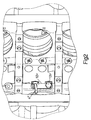
- the tab 12 is in turn by means of a screw 13 (Fig. 2) attached to the crankcase.
- the tab 12 provides an anti-rotation device the oil spray nozzle 4.
- a cylindrical shoulder 15 is used in the first hole 7 protrudes.
- the oil spray nozzle 4 is held by the screw 13. (Fig. 2).
- FIG. 2 An interior view of the crankcase is shown in FIG. 2.
- the oil spray nozzle 4 is attached to the crankcase by means of the screw 13 and bracket 12 and secured against twisting.
- the prefabricated unit from oil spray nozzle 4 and tab 12 can be installed positioned without much effort.
Landscapes
- Engineering & Computer Science (AREA)
- Mechanical Engineering (AREA)
- General Engineering & Computer Science (AREA)
- Lubrication Of Internal Combustion Engines (AREA)
Abstract
Description
- Fig. 1
- einen Querschnitt mit Ölspritzdüse und Schmierdüse
- Fig. 2
- eine Innenansicht des Kurbelgehäuses mit Ölspritzdüse und einer Lasche zur Befestigung derselben am Kurbelgehäuse
Claims (3)
- Brennkraftmaschine mit Kolbenkühlung und Schmierung eines Ventiltriebes, bei der Ölspritzdüsen zur Kühlung eines Kolbenbodens und Schmierdüsen zur Schmierung eines Ventiltriebes über einen gemeinsamen Ölkanal mit Öl versorgt werden und der Ölkanal ein Kurbelgehäuse achsparallel zu einer Kurbelwelle in voller Länge durchdringt, dadurch gekennzeichnet, daß die Ölspritzdüsen (4) und die Schmierdüsen (5) in koaxiale erste und zweite Bohrungen (7, 8) eingebaut sind, wobei erste Bohrungen (7) für den Einbau der Ölspritzdüsen (4) von Innenraum des Kurbelgehäuses ausgehen und im Ölkanal (6) münden und zweite Bohrungen (8) zur Versorgung von Rollenstößeln (2) mit Schmieröl vom Ölkanal (6) ausgehen und in Stößelführungen (9) münden, daß in die ersten Bohrungen (7) die Ölspritzdüsen (4) orientiert eingebaut sind und daß in die zweiten Bohrungen (8) die Schmierdüsen (5) eingebaut sind, welche gleichzeitig der Verdrehsicherung dienen.
- Brennkraftmaschine nach Anspruch 1, dadurch gekennzeichnet, daß das einem Rollenstößel (2) zugewandte freie Ende der Schmierdüse (5) in eine Längsnut (11) eines Stößelmantels (10) eingreift, derart, daß der Rollenstößel (2) axiale Bewegungen ungehindert ausführen kann, jedoch gegen Verdrehung gesichert ist.
- Brennkraftmaschine nach Anspruch 1, dadurch gekennzeichnet, daß die Ölspritzdüsen (4) mittels Laschen (12) und je einer Schraube (13) am Kurbelgehäuse befestigt sind und zur Abdichtung und Verdrehsicherung mittels eines zylindrischen Ansatzes (15) in den ersten Bohrungen (7) stecken.
Applications Claiming Priority (2)
| Application Number | Priority Date | Filing Date | Title |
|---|---|---|---|
| DE2001161610 DE10161610A1 (de) | 2001-12-14 | 2001-12-14 | Brennkraftmaschine mit Kolbenkühlung und Schmierung eines Ventiltriebes |
| DE10161610 | 2001-12-14 |
Publications (2)
| Publication Number | Publication Date |
|---|---|
| EP1319810A1 true EP1319810A1 (de) | 2003-06-18 |
| EP1319810B1 EP1319810B1 (de) | 2007-01-24 |
Family
ID=7709293
Family Applications (1)
| Application Number | Title | Priority Date | Filing Date |
|---|---|---|---|
| EP20020027805 Expired - Lifetime EP1319810B1 (de) | 2001-12-14 | 2002-12-12 | Brennkraftmaschine mit Kolbenkühlung und Schmierung eines Ventiltriebes |
Country Status (2)
| Country | Link |
|---|---|
| EP (1) | EP1319810B1 (de) |
| DE (2) | DE10161610A1 (de) |
Cited By (1)
| Publication number | Priority date | Publication date | Assignee | Title |
|---|---|---|---|---|
| KR20180085935A (ko) * | 2017-01-20 | 2018-07-30 | 두산인프라코어 주식회사 | 엔진의 롤러 태핏용 어댑터 및 이를 포함하는 엔진의 롤러 태핏 조립체 |
Citations (5)
| Publication number | Priority date | Publication date | Assignee | Title |
|---|---|---|---|---|
| DE4214839A1 (de) * | 1992-05-05 | 1993-11-11 | Audi Ag | Ventiltrieb für eine Brennkraftmaschine |
| US5503116A (en) * | 1993-12-23 | 1996-04-02 | Mercedes-Benz Ag | Arrangement for supplying liquids to a piston |
| FR2745329A1 (fr) * | 1996-02-23 | 1997-08-29 | Renault | Circuit de lubrification pour moteur a combustion interne |
| JPH09317428A (ja) * | 1996-06-03 | 1997-12-09 | Aisan Ind Co Ltd | エンジンのバルブ機構 |
| EP1077322A1 (de) * | 1999-08-16 | 2001-02-21 | Caterpillar Inc. | Kolbenbolzenschmierung für Brennkraftmaschine |
-
2001
- 2001-12-14 DE DE2001161610 patent/DE10161610A1/de not_active Withdrawn
-
2002
- 2002-12-12 DE DE50209333T patent/DE50209333D1/de not_active Expired - Lifetime
- 2002-12-12 EP EP20020027805 patent/EP1319810B1/de not_active Expired - Lifetime
Patent Citations (5)
| Publication number | Priority date | Publication date | Assignee | Title |
|---|---|---|---|---|
| DE4214839A1 (de) * | 1992-05-05 | 1993-11-11 | Audi Ag | Ventiltrieb für eine Brennkraftmaschine |
| US5503116A (en) * | 1993-12-23 | 1996-04-02 | Mercedes-Benz Ag | Arrangement for supplying liquids to a piston |
| FR2745329A1 (fr) * | 1996-02-23 | 1997-08-29 | Renault | Circuit de lubrification pour moteur a combustion interne |
| JPH09317428A (ja) * | 1996-06-03 | 1997-12-09 | Aisan Ind Co Ltd | エンジンのバルブ機構 |
| EP1077322A1 (de) * | 1999-08-16 | 2001-02-21 | Caterpillar Inc. | Kolbenbolzenschmierung für Brennkraftmaschine |
Non-Patent Citations (1)
| Title |
|---|
| PATENT ABSTRACTS OF JAPAN vol. 1998, no. 04 31 March 1998 (1998-03-31) * |
Cited By (3)
| Publication number | Priority date | Publication date | Assignee | Title |
|---|---|---|---|---|
| KR20180085935A (ko) * | 2017-01-20 | 2018-07-30 | 두산인프라코어 주식회사 | 엔진의 롤러 태핏용 어댑터 및 이를 포함하는 엔진의 롤러 태핏 조립체 |
| US20190353057A1 (en) * | 2017-01-20 | 2019-11-21 | Doosan Infracore Co., Ltd. | Adapter for roller tappet of engine and engine roller tappet assembly including same |
| US10975736B2 (en) * | 2017-01-20 | 2021-04-13 | Doosan Infracore Co., Ltd. | Adapter for roller tappet of engine and engine roller tappet assembly including same |
Also Published As
| Publication number | Publication date |
|---|---|
| DE50209333D1 (de) | 2007-03-15 |
| EP1319810B1 (de) | 2007-01-24 |
| DE10161610A1 (de) | 2003-06-26 |
Similar Documents
| Publication | Publication Date | Title |
|---|---|---|
| DE4227853A1 (de) | Kraftstoffeinspritzpumpe für Brennkraftmaschinen | |
| DE19712610C2 (de) | Halterungsvorrichtung für Ventilstößel und Verbrennungsmotor mit dieser Halterungsvorrichtung | |
| DE9405442U1 (de) | 4-Ventil-Kolbenbrennkraftmaschine | |
| DE10033367C2 (de) | Brennkraftmaschine, insbesondere für Motorräder | |
| DE19654926C2 (de) | Vorrichtung zur relativen Winkelverstellung einer Nockenwelle | |
| DE2343269A1 (de) | Hydraulisches spielausgleichselement fuer die ventilsteuerung von brennkraftmaschinen | |
| DE102012207951B4 (de) | Kolben einer Brennkraftmaschine | |
| DE4116942C1 (en) | Cylinder head for multicylinder IC engine - has accessory cover bolts with oil bores for guiding oil to bearing points and valve tappets | |
| EP2088310A1 (de) | Brennkraftmaschine mit einem Common-Rail-Einspritzsystem | |
| DE9412789U1 (de) | Nockenfolger eines Ventiltriebs einer Brennkraftmaschine | |
| DE4139446C2 (de) | ||
| DE102006038680B4 (de) | Schmiereinrichtung für einen Ventiltrieb einer Brennkraftmaschine | |
| EP0468202B1 (de) | Rollenstössel mit einem hydraulischen Ausgleichselement | |
| DE4225363A1 (de) | Kraftstoffeinspritzpumpe für Brennkraftmaschinen | |
| DE4128813A1 (de) | Hydraulischer rollenstoessel | |
| DE19611365A1 (de) | Vorrichtung zur relativen Winkelverstellung einer Nockenwelle | |
| EP1319810A1 (de) | Brennkraftmaschine mit Kolbenkühlung und Schmierung eines Ventiltriebes | |
| DE3637906A1 (de) | Sich selbsttaetig hydraulisch einstellender ventilstoessel | |
| DE10024207A1 (de) | Kolbenkühlung für Brennkraftmaschinen | |
| DE3541700A1 (de) | Brennkraftmaschine mit mindestens einer obenliegenden nockenwelle | |
| EP0659989A1 (de) | Vorrichtung zur Zufuhr von Flüssigkeiten in einen Kolben | |
| DE10021220A1 (de) | Brennkraftmaschine mit einem Kettentrieb | |
| DE4106800A1 (de) | Hydraulischer ventilstoessel fuer brennkraftmaschinen | |
| DE4409555C2 (de) | Vorrichtung zur Druckerzeugung für eine Druckölsperre einer Einspritzpumpe | |
| DE102008005768A1 (de) | Abstützelement für die Ventilsteuerung einer Brennkraftmaschine |
Legal Events
| Date | Code | Title | Description |
|---|---|---|---|
| PUAI | Public reference made under article 153(3) epc to a published international application that has entered the european phase |
Free format text: ORIGINAL CODE: 0009012 |
|
| AK | Designated contracting states |
Designated state(s): AT BE BG CH CY CZ DE DK EE ES FI FR GB GR IE IT LI LU MC NL PT SE SI SK TR |
|
| AX | Request for extension of the european patent |
Extension state: AL LT LV MK RO |
|
| 17P | Request for examination filed |
Effective date: 20030804 |
|
| AKX | Designation fees paid |
Designated state(s): DE FR IT NL SE |
|
| GRAP | Despatch of communication of intention to grant a patent |
Free format text: ORIGINAL CODE: EPIDOSNIGR1 |
|
| GRAS | Grant fee paid |
Free format text: ORIGINAL CODE: EPIDOSNIGR3 |
|
| GRAA | (expected) grant |
Free format text: ORIGINAL CODE: 0009210 |
|
| AK | Designated contracting states |
Kind code of ref document: B1 Designated state(s): DE FR IT NL SE |
|
| REF | Corresponds to: |
Ref document number: 50209333 Country of ref document: DE Date of ref document: 20070315 Kind code of ref document: P |
|
| REG | Reference to a national code |
Ref country code: SE Ref legal event code: TRGR |
|
| ET | Fr: translation filed | ||
| PLBE | No opposition filed within time limit |
Free format text: ORIGINAL CODE: 0009261 |
|
| STAA | Information on the status of an ep patent application or granted ep patent |
Free format text: STATUS: NO OPPOSITION FILED WITHIN TIME LIMIT |
|
| 26N | No opposition filed |
Effective date: 20071025 |
|
| REG | Reference to a national code |
Ref country code: NL Ref legal event code: TD Effective date: 20110304 |
|
| REG | Reference to a national code |
Ref country code: FR Ref legal event code: CD |
|
| REG | Reference to a national code |
Ref country code: DE Ref legal event code: R081 Ref document number: 50209333 Country of ref document: DE Owner name: MAN TRUCK & BUS AG, DE Free format text: FORMER OWNER: MAN NUTZFAHRZEUGE AG, 80995 MUENCHEN, DE Effective date: 20110406 |
|
| REG | Reference to a national code |
Ref country code: FR Ref legal event code: PLFP Year of fee payment: 14 |
|
| REG | Reference to a national code |
Ref country code: FR Ref legal event code: PLFP Year of fee payment: 15 |
|
| REG | Reference to a national code |
Ref country code: FR Ref legal event code: PLFP Year of fee payment: 16 |
|
| REG | Reference to a national code |
Ref country code: DE Ref legal event code: R081 Ref document number: 50209333 Country of ref document: DE Owner name: MAN TRUCK & BUS SE, DE Free format text: FORMER OWNER: MAN TRUCK & BUS AG, 80995 MUENCHEN, DE |
|
| PGFP | Annual fee paid to national office [announced via postgrant information from national office to epo] |
Ref country code: SE Payment date: 20211222 Year of fee payment: 20 Ref country code: FR Payment date: 20211227 Year of fee payment: 20 |
|
| PGFP | Annual fee paid to national office [announced via postgrant information from national office to epo] |
Ref country code: NL Payment date: 20211229 Year of fee payment: 20 Ref country code: IT Payment date: 20211220 Year of fee payment: 20 |
|
| PGFP | Annual fee paid to national office [announced via postgrant information from national office to epo] |
Ref country code: DE Payment date: 20220225 Year of fee payment: 20 |
|
| REG | Reference to a national code |
Ref country code: DE Ref legal event code: R071 Ref document number: 50209333 Country of ref document: DE |
|
| REG | Reference to a national code |
Ref country code: NL Ref legal event code: MK Effective date: 20221211 |
|
| REG | Reference to a national code |
Ref country code: SE Ref legal event code: EUG |