EP1319633B1 - Vorrichtung zum Greifen und Transportieren von Glasartikeln in einer Glasformmaschine - Google Patents
Vorrichtung zum Greifen und Transportieren von Glasartikeln in einer Glasformmaschine Download PDFInfo
- Publication number
- EP1319633B1 EP1319633B1 EP02027924A EP02027924A EP1319633B1 EP 1319633 B1 EP1319633 B1 EP 1319633B1 EP 02027924 A EP02027924 A EP 02027924A EP 02027924 A EP02027924 A EP 02027924A EP 1319633 B1 EP1319633 B1 EP 1319633B1
- Authority
- EP
- European Patent Office
- Prior art keywords
- unit
- gripping
- glass articles
- hinge axis
- crank
- Prior art date
- Legal status (The legal status is an assumption and is not a legal conclusion. Google has not performed a legal analysis and makes no representation as to the accuracy of the status listed.)
- Expired - Lifetime
Links
- 239000011521 glass Substances 0.000 title claims abstract description 17
- 238000000465 moulding Methods 0.000 title claims abstract description 15
- 238000001816 cooling Methods 0.000 claims 1
- 230000008878 coupling Effects 0.000 claims 1
- 238000010168 coupling process Methods 0.000 claims 1
- 238000005859 coupling reaction Methods 0.000 claims 1
- 230000005540 biological transmission Effects 0.000 description 3
- 238000010276 construction Methods 0.000 description 2
- 239000012530 fluid Substances 0.000 description 2
- 230000001050 lubricating effect Effects 0.000 description 2
- 238000004140 cleaning Methods 0.000 description 1
- 239000012809 cooling fluid Substances 0.000 description 1
- 239000000428 dust Substances 0.000 description 1
- 238000012423 maintenance Methods 0.000 description 1
- 230000009347 mechanical transmission Effects 0.000 description 1
- 230000002035 prolonged effect Effects 0.000 description 1
- 238000007789 sealing Methods 0.000 description 1
Images

Classifications
-
- C—CHEMISTRY; METALLURGY
- C03—GLASS; MINERAL OR SLAG WOOL
- C03B—MANUFACTURE, SHAPING, OR SUPPLEMENTARY PROCESSES
- C03B9/00—Blowing glass; Production of hollow glass articles
- C03B9/30—Details of blowing glass; Use of materials for the moulds
- C03B9/44—Means for discharging combined with glass-blowing machines, e.g. take-outs
- C03B9/447—Means for the removal of glass articles from the blow-mould, e.g. take-outs
Definitions
- the present invention relates to a unit for gripping and handling glass articles on a machine for molding glass articles, in particular a so-called I.S. molding machine.
- I.S. machines comprise a number of molding sections, each comprising a rough mold, a finish mold, and a gripping and handling unit for gripping the glass articles formed in the relative finish mold and transferring them onto a supporting surface, from which they are fed onto a conveyor common to all the machine sections.
- Known gripping and handling units comprise a supporting upright extending above the supporting surface and supporting a gripping device having a normally gripper-type gripping head, which is movable between a gripping position to remove the articles from the relative mold, and a release position to release the articles onto the supporting surface.
- the head is normally moved between said positions by means of an actuating device comprising a linear actuator normally housed in a cavity beneath the supporting surface and connected to the head by a gear transmission, normally a rack and pinion type extending at least partly through the upright.
- actuating devices of the above type are unsatisfactory by, above all, failing to set the head to the same gripping and release positions at all times, so that the glass articles - just removed from the finish mold and therefor still hot and extremely fragile - are frequently damaged and at times even shattered, thus creating product quality and machine maintenance and cleaning problems. This is mainly due to the construction design of the actuating devices, and to the difficulty in controlling the devices, particularly after prolonged operation.
- GB2095863 shows a take-out mechanism having a vertical support carrying an electric motor, which has an output shaft extending along a hinge axis of the take-out arm.
- a unit for gripping and handling glass articles on a machine for molding glass articles as defined in claim 1.
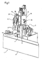
- Number 1 in Figure 1 indicates as a whole a machine (shown partly) for molding glass articles, and in particular a so-called I.S. machine for molding hollow glass articles 2 - in the example shown, bottles.
- Machine 1 comprises a bed 3 defining a horizontal top supporting surface 4; and a number of molding sections 5, one of which is shown partly in Figure 1 .
- Each molding section 5 comprises a rough mold (not shown); a finish mold 7; and a gripping and handling, or so-called "take-out", unit 8 for gripping articles 2 formed in finish mold 7, and transferring them onto surface 4, from which articles 2 are then pushed in known manner onto a belt conveyor common to all of molding sections 5.
- unit 8 comprises a rectangular-section upright 9, which is fitted in known manner to bed 3, is adjustable in height, projects upwards above supporting surface 4, and is fitted on the top end with a substantially parallelepiped-shaped frame 10 supporting a known gripping head 11, not described in detail, for gripping and handling articles 2.
- frame 10 comprises two facing lateral portions or shoulders 12 and 13; and an annular intermediate portion 14, which defines an annular conduit 14a for a cooling fluid, and extends between lateral portions 12 and 13 to define, with portions 12 and 13, a cavity 15.
- Lateral portion 12 comprises a hollow hub 16 extending inside cavity 15, coaxially with a horizontal axis 18, and engaged by an intermediate portion 19 of a fixed supporting shaft 20 coaxial with axis 18.
- Shaft 20 also comprises an end portion 21 extending outside frame 10 and fitted in rotary and axially-fixed manner with an end portion 22 of a crank 23, an opposite end portion 24 of which is hinged to gripping head 11 about a hinge axis parallel to axis 18.
- Crank 23 is rotated in opposite directions about axis 18 by a rotary motor 25, conveniently an electric motor housed in cavity 15 and coaxial with axis 18, to move gripping head 11 between a gripping position to remove articles 2 from finish mold 7, and a release position to release the removed articles 2 onto supporting surface 4.
- motor 25 comprises an annular stator 26 connected integrally to intermediate portion 14; and a tubular rotor 27 extending between lateral portions 12 and 13, coaxially with axis 18, and connected to lateral portions 12 and 13 in rotary and axially-fixed manner by two bearings 28.
- Rotor 27 partly surrounds hub 16, and is connected to portion 22 of crank 23 in angularly-fixed manner by two axial teeth 30 (only one shown in Figure 2 ), which are integral with and project axially from rotor 27, and each of which engages in axially-sliding and angularly-fixed manner a respective axial seat 31 formed in portion 22 of crank 23.
- Rotor 27 and hub 16 are designed to define, between them, an airtight annular chamber 33 housing a known position transducer 34.
- motor 25 has an axial dimension substantially equal to that of frame 10 measured in the same direction, and which conveniently ranges between 100 and 200 mm and is preferably such that the outside dimension of frame 10, measured parallel to axis 18, is substantially equal to the outside dimension of upright 9 measured in the same direction.
- unit 8 comprising a rotary motor, and the rotary motor being connected directly to the gripping head crank, movement of the crank is therefore extremely accurate to set the gripping head to the same gripping and release positions at all times, thus ensuring consistent quality of the articles in terms of shape and size.
- location of motor 25 coaxial with the crank rotation axis 18 provides for eliminating both the actuator beneath the supporting surface and the transmission through upright 9, so that, on the one hand, the space formerly occupied by the actuator is made available, and, on the other, upright 9 can be shaped and sized for maximum compactness and easy access to the components to the rear of gripping unit 8. What is more, eliminating the gripping head transmission components extending through the upright makes the gripping head much easier to change.
- operating head 11 by means of a single rotary motor coaxial to axis 18 greatly simplifies the structure of supporting frame 10 and the sealing devices, which, by eliminating the lubricating fluid in frame 10 and upright 9, are restricted to straightforward dust seals.
- Supporting frame 10 may be other than as described by way of example; and a motor other than the one described may be used, providing it is connected to the crank with no mechanical transmissions with relatively-moving parts in between.
Landscapes
- Engineering & Computer Science (AREA)
- Chemical & Material Sciences (AREA)
- Manufacturing & Machinery (AREA)
- Materials Engineering (AREA)
- Organic Chemistry (AREA)
- Manipulator (AREA)
- Moulds For Moulding Plastics Or The Like (AREA)
- Specific Conveyance Elements (AREA)
- Glass Compositions (AREA)
- Manufacture, Treatment Of Glass Fibers (AREA)
Claims (10)
- Eine Einheit (8) zum Greifen und Befördern von Glasartikeln (2) an einer Maschine (1) zum Formen von Glasartikeln, wobei die Einheit (8) aufweist:- Stützmittel (9, 10), die an einer Struktur (3) der Formmaschine (1) anbringbar sind,- einen Greifkopf (11) zum Angreifen an den Glasartikeln (2) zum Entnehmen,- eine Kurbel (23), aufweisend einen ersten Abschnitt (22), der an die Stützmittel (9, 10) angelenkt ist, um sich um eine erste Gelenkachse (18) zu drehen, und einen zweiten Abschnitt (24), der an den Greifkopf angelenkt ist, um sich um eine zweite Achse parallel zu der ersten Gelenkachse (18) zu drehen, und- Betätigungsmittel (19, 25) zum Drehen der Kurbel (23) bezüglich der Stützmittel (9, 10) in entgegengesetzten Richtungen um die erste Gelenkachse (18) und zum Bewegen des Greifkopfes (11) zwischen einer Greifposition und einer Löseposition zum Greifen bzw. Loslassen der Artikel (2), wobei die Betätigungsmittel (19, 25) einen Rotationselektromotor (25) aufweisen, der ein bewegbares Element (27) aufweist, das sich um eine mit der ersten Gelenkachse (18) zusammenfallende Achse dreht,dadurch gekennzeichnet, dass sie ferner Winkeldetektionsmittel (34) zum Detektieren der Position des bewegbaren Elements (27) aufweist und der Motor einen rohrförmigen Rotor (27) aufweist, der das bewegbare Element definiert und die Winkeldetektionsmittel (34) aufnimmt.
- Eine Einheit gemäß Anspruch 1, dadurch gekennzeichnet, dass die Stützmittel einen Rahmen (10) aufweisen, der seinerseits zwei einander zugewandte Seitenabschnitte (12) (13) und einen dazwischenliegenden ringförmigen Umfangsabschnitt (14) aufweist, der sich zwischen den Seitenabschnitten (12) (13) erstreckt und einstückig mit den Seitenabschnitten (12) (13) verbunden ist, wobei der rohrförmige Rotor (27) drehbar und axialfest mit den Seitenabschnitten (12, 13) verbunden ist und zusammen mit einem der Seitenabschnitte (12) eine luftdichte Kammer (33) definiert, wobei die luftdichte Kammer (33) die Winkeldetektionsmittel (34) aufnimmt.
- Eine Einheit gemäß Anspruch 2, dadurch gekennzeichnet, dass ein Seitenabschnitt (12) eine hohle Nabe (16) aufweist, die sich koaxial zu der ersten Gelenkachse (18) erstreckt, wobei der rohrförmige Rotor (27) die Nabe (16) teilweise umgibt, wobei die luftdichte Kammer (33) von dem rohrförmigen Rotor (27) und der hohlen Nabe (16) definiert wird.
- Eine Einheit gemäß Anspruch 2 oder 3, dadurch gekennzeichnet, dass der Motor einen Stator (26) aufweist, der einstückig mit dem ringförmigen Abschnitt (14) verbunden ist.
- Eine Einheit gemäß einem der Ansprüche 2 bis 4,
dadurch gekennzeichnet, dass der ringförmige Abschnitt (14) eine ringförmige Umfangs-Kühlleitung (14a) definiert. - Eine Einheit gemäß einem der Ansprüche 2 bis 5,
dadurch gekennzeichnet, dass die Stützmittel einen Ständer (9) zum Abstützen des Rahmens (10) aufweisen, wobei der Rahmen (10) am oberen Ende des Ständers (9) angeordnet ist und parallel zu der ersten Gelenkachse (18) gemessen eine Maximalabmessung aufweist, die im Wesentlichen gleich einer Abmessung des Ständers (9) ist, die in derselben Richtung gemessen wird. - Eine Einheit gemäß einem der Ansprüche 2 bis 6,
dadurch gekennzeichnet, dass der Motor parallel zu der ersten Gelenkachse (18) gemessen eine Axialabmessung aufweist, die, gemessen in derselben Richtung, höchstens gleich derjenigen des Rahmens (10) ist. - Eine Einheit gemäß Anspruch 7, dadurch gekennzeichnet, dass die Abmessung zwischen 100 mm und 200 mm liegt.
- Eine Einheit gemäß einem der vorhergehenden Ansprüche, dadurch gekennzeichnet, dass der erste Abschnitt (22) der Kurbel (23) direkt mit dem rohrförmigen Rotor (27) verbunden ist.
- Eine Einheit gemäß Anspruch 9, dadurch gekennzeichnet dass der rohrförmige Rotor (27) durch Winkelkupplungsmittel mit Außenzähnen (30) mit der Kurbel (23) verbunden ist.
Applications Claiming Priority (2)
| Application Number | Priority Date | Filing Date | Title |
|---|---|---|---|
| IT2001TO001167A ITTO20011167A1 (it) | 2001-12-14 | 2001-12-14 | Gruppo di presa e movimentazione articoli di vetro per una macchina di formatura di articoli di vetro. |
| ITTO20011167 | 2001-12-14 |
Publications (3)
| Publication Number | Publication Date |
|---|---|
| EP1319633A2 EP1319633A2 (de) | 2003-06-18 |
| EP1319633A3 EP1319633A3 (de) | 2004-05-12 |
| EP1319633B1 true EP1319633B1 (de) | 2011-08-24 |
Family
ID=11459336
Family Applications (1)
| Application Number | Title | Priority Date | Filing Date |
|---|---|---|---|
| EP02027924A Expired - Lifetime EP1319633B1 (de) | 2001-12-14 | 2002-12-13 | Vorrichtung zum Greifen und Transportieren von Glasartikeln in einer Glasformmaschine |
Country Status (4)
| Country | Link |
|---|---|
| EP (1) | EP1319633B1 (de) |
| AT (1) | ATE521579T1 (de) |
| ES (1) | ES2369202T3 (de) |
| IT (1) | ITTO20011167A1 (de) |
Families Citing this family (1)
| Publication number | Priority date | Publication date | Assignee | Title |
|---|---|---|---|---|
| DE202004003892U1 (de) * | 2004-03-12 | 2005-04-21 | Heye International Gmbh | Vorrichtung zum Überschieben von Hohlglasgegenständen aus einer Glasformmaschine auf ein Transportband |
Family Cites Families (8)
| Publication number | Priority date | Publication date | Assignee | Title |
|---|---|---|---|---|
| CA1192406A (en) * | 1981-03-30 | 1985-08-27 | Eustace H. Mumford | Electronic control glass forming machine |
| JP2532040B2 (ja) * | 1987-07-08 | 1996-09-11 | 日本耐酸壜工業株式会社 | 製びん機におけるびん体の移送装置 |
| GB2231855A (en) * | 1989-04-27 | 1990-11-28 | * Emhart Industries,Inc. | Pushout mechanism |
| DE4231454C2 (de) * | 1992-09-19 | 1995-06-22 | Gps Glasprod Serv Gmbh | Abgabestation für eine IS-Glasformmaschine |
| GB9705973D0 (en) * | 1997-03-22 | 1997-05-07 | Vhc Ltd | Drive mechanism for a tong arm |
| US5895513A (en) * | 1997-11-06 | 1999-04-20 | Emhart Glass Machinery Investments Inc. | Takeout mechanism for an I.S. machine |
| DE29810353U1 (de) * | 1998-06-12 | 1999-07-15 | Fa. Hermann Heye, 31683 Obernkirchen | Ausnehmer-Mechanismus für eine Glasformmaschine |
| JP3140434B2 (ja) * | 1999-05-14 | 2001-03-05 | 東洋ガラス株式会社 | 製びん機のテークアウトメカニズム |
-
2001
- 2001-12-14 IT IT2001TO001167A patent/ITTO20011167A1/it unknown
-
2002
- 2002-12-13 AT AT02027924T patent/ATE521579T1/de not_active IP Right Cessation
- 2002-12-13 ES ES02027924T patent/ES2369202T3/es not_active Expired - Lifetime
- 2002-12-13 EP EP02027924A patent/EP1319633B1/de not_active Expired - Lifetime
Also Published As
| Publication number | Publication date |
|---|---|
| ES2369202T3 (es) | 2011-11-28 |
| ITTO20011167A1 (it) | 2003-06-16 |
| EP1319633A2 (de) | 2003-06-18 |
| ITTO20011167A0 (it) | 2001-12-14 |
| ATE521579T1 (de) | 2011-09-15 |
| EP1319633A3 (de) | 2004-05-12 |
Similar Documents
| Publication | Publication Date | Title |
|---|---|---|
| US7497323B2 (en) | Machine for aligning and equipping articles | |
| US8631926B2 (en) | Device for pushing glass objects onto a conveyor belt | |
| US9567165B2 (en) | Transport device for containers | |
| RU2330818C2 (ru) | Устройство транспортировки изделий из фиксированного положения на движущийся конвейер | |
| EP1319633B1 (de) | Vorrichtung zum Greifen und Transportieren von Glasartikeln in einer Glasformmaschine | |
| CN111655640A (zh) | 一种用于将玻璃管制成玻璃容器的热成型装置 | |
| US8381898B2 (en) | Apparatus for pushing glass articles onto a belt conveyor | |
| EP1886977B1 (de) | Abschiebevorrichtung für eine Glasformmaschine | |
| JP4209487B2 (ja) | 包装機、特に煙草パック製造用包装機 | |
| JPH07237745A (ja) | 異径容器用容器保持具 | |
| KR101445886B1 (ko) | 유리 고브 분배 | |
| RU2495835C1 (ru) | Устройство для передвигания стеклянных предметов на транспортерную ленту | |
| US6386000B1 (en) | I.S. machine | |
| WO2020158703A1 (ja) | ロータリー成形機 | |
| EP0866036B1 (de) | Getriebe für ein Ausnehmmechanismus | |
| CA2547758A1 (en) | Article-positioning machine | |
| EP0712812B1 (de) | Schneidevorrichtung, insbesondere für geschmolzene Glastropfen | |
| KR100304452B1 (ko) | 정밀 로봇의 직동 및 회전 운동 장치 | |
| JP4778165B2 (ja) | トランスファ送り装置 | |
| GB2357284A (en) | IS machine mold halves of varying diameter for use in a single holder | |
| ES2238351T3 (es) | Unidad inversora para una maquina de moldear articulos de vidrio. | |
| JP4350823B2 (ja) | I.s.機械用の金型開閉機構 | |
| CN218214981U (zh) | 一种环形磁芯排列装置 | |
| CN112697710A (zh) | 转盘托压式灯检机主轴跟踪传动机构 | |
| SU1459897A1 (ru) | Приемно-передаточное устройство |
Legal Events
| Date | Code | Title | Description |
|---|---|---|---|
| PUAI | Public reference made under article 153(3) epc to a published international application that has entered the european phase |
Free format text: ORIGINAL CODE: 0009012 |
|
| AK | Designated contracting states |
Designated state(s): AT BE BG CH CY CZ DE DK EE ES FI FR GB GR IE IT LI LU MC NL PT SE SI SK TR |
|
| AX | Request for extension of the european patent |
Extension state: AL LT LV MK RO |
|
| PUAL | Search report despatched |
Free format text: ORIGINAL CODE: 0009013 |
|
| AK | Designated contracting states |
Kind code of ref document: A3 Designated state(s): AT BE BG CH CY CZ DE DK EE ES FI FR GB GR IE IT LI LU MC NL PT SE SI SK TR |
|
| AX | Request for extension of the european patent |
Extension state: AL LT LV MK RO |
|
| 17P | Request for examination filed |
Effective date: 20041111 |
|
| AKX | Designation fees paid |
Designated state(s): AT BE BG CH CY CZ DE DK EE ES FI FR GB GR IE IT LI LU MC NL PT SE SI SK TR |
|
| 17Q | First examination report despatched |
Effective date: 20050304 |
|
| GRAJ | Information related to disapproval of communication of intention to grant by the applicant or resumption of examination proceedings by the epo deleted |
Free format text: ORIGINAL CODE: EPIDOSDIGR1 |
|
| GRAP | Despatch of communication of intention to grant a patent |
Free format text: ORIGINAL CODE: EPIDOSNIGR1 |
|
| GRAS | Grant fee paid |
Free format text: ORIGINAL CODE: EPIDOSNIGR3 |
|
| GRAA | (expected) grant |
Free format text: ORIGINAL CODE: 0009210 |
|
| AK | Designated contracting states |
Kind code of ref document: B1 Designated state(s): AT BE BG CH CY CZ DE DK EE ES FI FR GB GR IE IT LI LU MC NL PT SE SI SK TR |
|
| REG | Reference to a national code |
Ref country code: GB Ref legal event code: FG4D |
|
| REG | Reference to a national code |
Ref country code: CH Ref legal event code: EP |
|
| REG | Reference to a national code |
Ref country code: IE Ref legal event code: FG4D |
|
| REG | Reference to a national code |
Ref country code: CH Ref legal event code: NV Representative=s name: BOVARD AG |
|
| REG | Reference to a national code |
Ref country code: DE Ref legal event code: R096 Ref document number: 60240847 Country of ref document: DE Effective date: 20111020 |
|
| REG | Reference to a national code |
Ref country code: ES Ref legal event code: FG2A Ref document number: 2369202 Country of ref document: ES Kind code of ref document: T3 Effective date: 20111128 |
|
| REG | Reference to a national code |
Ref country code: SE Ref legal event code: TRGR |
|
| REG | Reference to a national code |
Ref country code: NL Ref legal event code: VDEP Effective date: 20110824 |
|
| PG25 | Lapsed in a contracting state [announced via postgrant information from national office to epo] |
Ref country code: PT Free format text: LAPSE BECAUSE OF FAILURE TO SUBMIT A TRANSLATION OF THE DESCRIPTION OR TO PAY THE FEE WITHIN THE PRESCRIBED TIME-LIMIT Effective date: 20111226 Ref country code: NL Free format text: LAPSE BECAUSE OF FAILURE TO SUBMIT A TRANSLATION OF THE DESCRIPTION OR TO PAY THE FEE WITHIN THE PRESCRIBED TIME-LIMIT Effective date: 20110824 Ref country code: FI Free format text: LAPSE BECAUSE OF FAILURE TO SUBMIT A TRANSLATION OF THE DESCRIPTION OR TO PAY THE FEE WITHIN THE PRESCRIBED TIME-LIMIT Effective date: 20110824 |
|
| PGFP | Annual fee paid to national office [announced via postgrant information from national office to epo] |
Ref country code: ES Payment date: 20111212 Year of fee payment: 10 |
|
| REG | Reference to a national code |
Ref country code: AT Ref legal event code: MK05 Ref document number: 521579 Country of ref document: AT Kind code of ref document: T Effective date: 20110824 |
|
| PG25 | Lapsed in a contracting state [announced via postgrant information from national office to epo] |
Ref country code: CY Free format text: LAPSE BECAUSE OF FAILURE TO SUBMIT A TRANSLATION OF THE DESCRIPTION OR TO PAY THE FEE WITHIN THE PRESCRIBED TIME-LIMIT Effective date: 20110824 Ref country code: GR Free format text: LAPSE BECAUSE OF FAILURE TO SUBMIT A TRANSLATION OF THE DESCRIPTION OR TO PAY THE FEE WITHIN THE PRESCRIBED TIME-LIMIT Effective date: 20111125 Ref country code: AT Free format text: LAPSE BECAUSE OF FAILURE TO SUBMIT A TRANSLATION OF THE DESCRIPTION OR TO PAY THE FEE WITHIN THE PRESCRIBED TIME-LIMIT Effective date: 20110824 Ref country code: SI Free format text: LAPSE BECAUSE OF FAILURE TO SUBMIT A TRANSLATION OF THE DESCRIPTION OR TO PAY THE FEE WITHIN THE PRESCRIBED TIME-LIMIT Effective date: 20110824 |
|
| PG25 | Lapsed in a contracting state [announced via postgrant information from national office to epo] |
Ref country code: BE Free format text: LAPSE BECAUSE OF FAILURE TO SUBMIT A TRANSLATION OF THE DESCRIPTION OR TO PAY THE FEE WITHIN THE PRESCRIBED TIME-LIMIT Effective date: 20110824 |
|
| PG25 | Lapsed in a contracting state [announced via postgrant information from national office to epo] |
Ref country code: SK Free format text: LAPSE BECAUSE OF FAILURE TO SUBMIT A TRANSLATION OF THE DESCRIPTION OR TO PAY THE FEE WITHIN THE PRESCRIBED TIME-LIMIT Effective date: 20110824 |
|
| PGFP | Annual fee paid to national office [announced via postgrant information from national office to epo] |
Ref country code: FR Payment date: 20120119 Year of fee payment: 10 |
|
| PG25 | Lapsed in a contracting state [announced via postgrant information from national office to epo] |
Ref country code: IT Free format text: LAPSE BECAUSE OF FAILURE TO SUBMIT A TRANSLATION OF THE DESCRIPTION OR TO PAY THE FEE WITHIN THE PRESCRIBED TIME-LIMIT Effective date: 20110824 Ref country code: EE Free format text: LAPSE BECAUSE OF FAILURE TO SUBMIT A TRANSLATION OF THE DESCRIPTION OR TO PAY THE FEE WITHIN THE PRESCRIBED TIME-LIMIT Effective date: 20110824 |
|
| PG25 | Lapsed in a contracting state [announced via postgrant information from national office to epo] |
Ref country code: DK Free format text: LAPSE BECAUSE OF FAILURE TO SUBMIT A TRANSLATION OF THE DESCRIPTION OR TO PAY THE FEE WITHIN THE PRESCRIBED TIME-LIMIT Effective date: 20110824 |
|
| PLBE | No opposition filed within time limit |
Free format text: ORIGINAL CODE: 0009261 |
|
| STAA | Information on the status of an ep patent application or granted ep patent |
Free format text: STATUS: NO OPPOSITION FILED WITHIN TIME LIMIT |
|
| PG25 | Lapsed in a contracting state [announced via postgrant information from national office to epo] |
Ref country code: MC Free format text: LAPSE BECAUSE OF NON-PAYMENT OF DUE FEES Effective date: 20111231 |
|
| 26N | No opposition filed |
Effective date: 20120525 |
|
| REG | Reference to a national code |
Ref country code: DE Ref legal event code: R097 Ref document number: 60240847 Country of ref document: DE Effective date: 20120525 |
|
| REG | Reference to a national code |
Ref country code: IE Ref legal event code: MM4A |
|
| PG25 | Lapsed in a contracting state [announced via postgrant information from national office to epo] |
Ref country code: IE Free format text: LAPSE BECAUSE OF NON-PAYMENT OF DUE FEES Effective date: 20111213 |
|
| PG25 | Lapsed in a contracting state [announced via postgrant information from national office to epo] |
Ref country code: LU Free format text: LAPSE BECAUSE OF NON-PAYMENT OF DUE FEES Effective date: 20111213 |
|
| PG25 | Lapsed in a contracting state [announced via postgrant information from national office to epo] |
Ref country code: BG Free format text: LAPSE BECAUSE OF FAILURE TO SUBMIT A TRANSLATION OF THE DESCRIPTION OR TO PAY THE FEE WITHIN THE PRESCRIBED TIME-LIMIT Effective date: 20111124 |
|
| GBPC | Gb: european patent ceased through non-payment of renewal fee |
Effective date: 20121213 |
|
| REG | Reference to a national code |
Ref country code: FR Ref legal event code: ST Effective date: 20130830 |
|
| PG25 | Lapsed in a contracting state [announced via postgrant information from national office to epo] |
Ref country code: TR Free format text: LAPSE BECAUSE OF FAILURE TO SUBMIT A TRANSLATION OF THE DESCRIPTION OR TO PAY THE FEE WITHIN THE PRESCRIBED TIME-LIMIT Effective date: 20110824 |
|
| PG25 | Lapsed in a contracting state [announced via postgrant information from national office to epo] |
Ref country code: GB Free format text: LAPSE BECAUSE OF NON-PAYMENT OF DUE FEES Effective date: 20121213 Ref country code: FR Free format text: LAPSE BECAUSE OF NON-PAYMENT OF DUE FEES Effective date: 20130102 |
|
| REG | Reference to a national code |
Ref country code: ES Ref legal event code: FD2A Effective date: 20140527 |
|
| PG25 | Lapsed in a contracting state [announced via postgrant information from national office to epo] |
Ref country code: ES Free format text: LAPSE BECAUSE OF NON-PAYMENT OF DUE FEES Effective date: 20121214 |
|
| PGFP | Annual fee paid to national office [announced via postgrant information from national office to epo] |
Ref country code: CH Payment date: 20151119 Year of fee payment: 14 Ref country code: DE Payment date: 20151119 Year of fee payment: 14 |
|
| PGFP | Annual fee paid to national office [announced via postgrant information from national office to epo] |
Ref country code: SE Payment date: 20151124 Year of fee payment: 14 Ref country code: CZ Payment date: 20151123 Year of fee payment: 14 |
|
| REG | Reference to a national code |
Ref country code: DE Ref legal event code: R119 Ref document number: 60240847 Country of ref document: DE |
|
| PG25 | Lapsed in a contracting state [announced via postgrant information from national office to epo] |
Ref country code: CZ Free format text: LAPSE BECAUSE OF NON-PAYMENT OF DUE FEES Effective date: 20161213 |
|
| REG | Reference to a national code |
Ref country code: CH Ref legal event code: PL |
|
| REG | Reference to a national code |
Ref country code: SE Ref legal event code: EUG |
|
| PG25 | Lapsed in a contracting state [announced via postgrant information from national office to epo] |
Ref country code: SE Free format text: LAPSE BECAUSE OF NON-PAYMENT OF DUE FEES Effective date: 20161214 |
|
| PG25 | Lapsed in a contracting state [announced via postgrant information from national office to epo] |
Ref country code: LI Free format text: LAPSE BECAUSE OF NON-PAYMENT OF DUE FEES Effective date: 20161231 Ref country code: CH Free format text: LAPSE BECAUSE OF NON-PAYMENT OF DUE FEES Effective date: 20161231 |
|
| PG25 | Lapsed in a contracting state [announced via postgrant information from national office to epo] |
Ref country code: DE Free format text: LAPSE BECAUSE OF NON-PAYMENT OF DUE FEES Effective date: 20170701 |