EP1319555A2 - Explosionsgeschützte Batterieabdeckung für Kraftfahrzeuge - Google Patents
Explosionsgeschützte Batterieabdeckung für Kraftfahrzeuge Download PDFInfo
- Publication number
- EP1319555A2 EP1319555A2 EP02019687A EP02019687A EP1319555A2 EP 1319555 A2 EP1319555 A2 EP 1319555A2 EP 02019687 A EP02019687 A EP 02019687A EP 02019687 A EP02019687 A EP 02019687A EP 1319555 A2 EP1319555 A2 EP 1319555A2
- Authority
- EP
- European Patent Office
- Prior art keywords
- battery
- battery cover
- cover according
- electrically conductive
- cover
- Prior art date
- Legal status (The legal status is an assumption and is not a legal conclusion. Google has not performed a legal analysis and makes no representation as to the accuracy of the status listed.)
- Granted
Links
Images

Classifications
-
- B—PERFORMING OPERATIONS; TRANSPORTING
- B60—VEHICLES IN GENERAL
- B60R—VEHICLES, VEHICLE FITTINGS, OR VEHICLE PARTS, NOT OTHERWISE PROVIDED FOR
- B60R16/00—Electric or fluid circuits specially adapted for vehicles and not otherwise provided for; Arrangement of elements of electric or fluid circuits specially adapted for vehicles and not otherwise provided for
- B60R16/02—Electric or fluid circuits specially adapted for vehicles and not otherwise provided for; Arrangement of elements of electric or fluid circuits specially adapted for vehicles and not otherwise provided for electric constitutive elements
- B60R16/04—Arrangement of batteries
-
- B—PERFORMING OPERATIONS; TRANSPORTING
- B62—LAND VEHICLES FOR TRAVELLING OTHERWISE THAN ON RAILS
- B62D—MOTOR VEHICLES; TRAILERS
- B62D25/00—Superstructure or monocoque structure sub-units; Parts or details thereof not otherwise provided for
- B62D25/24—Superstructure sub-units with access or drainage openings having movable or removable closures; Sealing means therefor
-
- H—ELECTRICITY
- H01—ELECTRIC ELEMENTS
- H01M—PROCESSES OR MEANS, e.g. BATTERIES, FOR THE DIRECT CONVERSION OF CHEMICAL ENERGY INTO ELECTRICAL ENERGY
- H01M2220/00—Batteries for particular applications
- H01M2220/20—Batteries in motive systems, e.g. vehicle, ship, plane
-
- Y—GENERAL TAGGING OF NEW TECHNOLOGICAL DEVELOPMENTS; GENERAL TAGGING OF CROSS-SECTIONAL TECHNOLOGIES SPANNING OVER SEVERAL SECTIONS OF THE IPC; TECHNICAL SUBJECTS COVERED BY FORMER USPC CROSS-REFERENCE ART COLLECTIONS [XRACs] AND DIGESTS
- Y02—TECHNOLOGIES OR APPLICATIONS FOR MITIGATION OR ADAPTATION AGAINST CLIMATE CHANGE
- Y02E—REDUCTION OF GREENHOUSE GAS [GHG] EMISSIONS, RELATED TO ENERGY GENERATION, TRANSMISSION OR DISTRIBUTION
- Y02E60/00—Enabling technologies; Technologies with a potential or indirect contribution to GHG emissions mitigation
- Y02E60/10—Energy storage using batteries
Definitions
- the invention relates to a plastic battery cover especially for the battery access opening in the water tank a Motor vehicle.
- the invention is therefore the object of a battery cover create the danger of such explosions by discharging static Charging voltages eliminated.
- the invention provides that the battery cover formed electrically conductive and directly to the negative terminal of the Battery is connected.
- the direct conductive connection between the electrically conductive battery cover and the negative pole of the battery can be replaced either by an insulating extended cable, the battery negative pole with the electric conductive battery cover connects so that the connection too persists when the lid is removed and laterally on the water box cover is filed.
- the compound can also by a on the battery negative pole captive mounted contact spring be realized the electrically contacting rests against the battery cover.
- This contact spring is designed so that it still has contact with the battery cover even if this is already lifted a piece or makes the contact again if the cover is still a long way above the water box cover is arranged so that in each case electrically conductive contact between the battery cover and the negative pole of the battery if the cover is still far enough away from the battery, so that no previous rollovers can take place.
- the battery cover in the area of the battery positive pole an isolation point has, for example, a filled by a plastic lid Recess or even a plastic coating, so that at a load the lid when supporting during maintenance no direct Contact between electrically conductive parts of the battery cover and the Positive pole can occur.
- the battery cover according to the invention can be made of metal or electrically conductive plastic, as well as an electrically insulating Plastic, which then at least partially with an electric conductive coating or liner is provided.
- an electrically conductive coating are a glued metal foil or a metallization or even an electrically conductive lacquer layer.
- Inlay comes in particular for contacting sections lying freely Metal net into consideration.
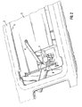
- Fig. 1 shows a section of the below the windshield arranged in the engine compartment water tank 1 with a closed Plastic cover 2 in the built-in battery 3 a removable Battery cover 4 is provided, which provides free access to Battery releases, so both are performed on their maintenance Both the battery and the battery can be fully lifted out when needed can.
- This battery cover 4 covers a battery access opening 5 of the plastic cover 2.
- a contact spring 8 is mounted, which contacts from below at the electrically conductive, so for example made of metal battery cover 4 is present.
- the spring is designed so long and so bent that the contacting of the electrically conductive battery cover 4 already before putting on the plastic cover uses and also another There is a long time when the battery cover is removed.
- the electrically conductive battery cover In the area 9 above the positive pole 10 of the battery 8, the electrically conductive battery cover have an isolation point, either through an insulating layer on the underside or a release of the applied metal layer, or by a recess made of metal Battery cover may be formed, in which a plastic lid is inserted is.
Landscapes
- Engineering & Computer Science (AREA)
- Mechanical Engineering (AREA)
- Chemical & Material Sciences (AREA)
- Combustion & Propulsion (AREA)
- Transportation (AREA)
- Battery Mounting, Suspending (AREA)
- Connection Of Batteries Or Terminals (AREA)
Abstract
Description
- Fig. 1
- einen Aussschnitt des Wasserkastens eines Kraftfahrzeugs mit Kunststoffabdeckung in die eine herausnehmbare Batterieabdeckung integriert ist, und
- Fig. 2
- eine vergrößerte Ansicht eines Teilbereichs bei abgenommener Batterieabdeckung.
Claims (9)
- Aus Kunststoff bestehende Batterieabdeckung, insbesondere für die Batteriezugangsöffnung im Wasserkasten eines Kraftfahrzeugs,
dadurch gekennzeichnet, dass sie elektrisch leitend ausgebildet und direkt mit dem Minuspol der Batterie verbunden ist. - Batterieabdeckung nach Anspruch 1,
dadurch gekennzeichnet, dass sie durch einen isolierten ein Öffnen und Ablegen ermöglichenden, verlängerten isolierten Leiter mit dem Batterie-Minuspol verbunden ist. - Batterieabdeckung nach Anspruch 1,
dadurch gekennzeichnet, dass die elektrische Verbindung eine am Batterie-Minuspol unverlierbar angebrachte Kontaktfeder umfasst. - Batterieabdeckung nach einem der Ansprüche 1 bis 3,
dadurch gekennzeichnet, dass sie im Bereich des Batterie-Pluspols eine Isolierungsstelle aufweist. - Batterieabdeckung nach einem der Ansprüche 1 bis 4,
dadurch gekennzeichnet, dass sie aus Metall besteht. - Batterieabdeckung nach einem der Ansprüche 1 bis 4,
dadurch gekennzeichnet, dass sie aus elektrisch leitendem Kunststoff besteht. - Batterieabdeckung nach einem der Ansprüche 1 bis 4,
dadurch gekennzeichnet, dass sie aus elektrisch isolierendem Kunststoff besteht, der zumindest abschnittsweise mit einer elektrisch leitfähigen Beschichtung oder Einlage versehen ist. - Batterieabdeckung nach Anspruch 7,
dadurch gekennzeichnet, dass die Beschichtung eine Metallfolie, eine Metallisierung oder eine elektrisch leitfähige Lackschicht ist. - Batterieabdeckung nach Anspruch 7,
dadurch gekennzeichnet, dass die Einlage ein zur Kontaktierung abschnittsweise freiligendes Metallnetz ist.
Applications Claiming Priority (4)
| Application Number | Priority Date | Filing Date | Title |
|---|---|---|---|
| DE10161566 | 2001-12-14 | ||
| DE10161566A DE10161566C1 (de) | 2001-12-14 | 2001-12-14 | Explosionsgeschützte Batteriabdeckung für Kraftfahrzeuge |
| DE20204964U DE20204964U1 (de) | 2001-12-14 | 2002-03-28 | Explosionsgeschützte Batterieabdeckung für Kraftfahrzeuge |
| DE20204964U | 2002-03-28 |
Publications (3)
| Publication Number | Publication Date |
|---|---|
| EP1319555A2 true EP1319555A2 (de) | 2003-06-18 |
| EP1319555A3 EP1319555A3 (de) | 2003-09-03 |
| EP1319555B1 EP1319555B1 (de) | 2005-12-07 |
Family
ID=26010781
Family Applications (1)
| Application Number | Title | Priority Date | Filing Date |
|---|---|---|---|
| EP02019687A Expired - Lifetime EP1319555B1 (de) | 2001-12-14 | 2002-09-04 | Explosionsgeschützte Batterieabdeckung für Kraftfahrzeuge |
Country Status (2)
| Country | Link |
|---|---|
| EP (1) | EP1319555B1 (de) |
| DE (1) | DE50205182D1 (de) |
Family Cites Families (3)
| Publication number | Priority date | Publication date | Assignee | Title |
|---|---|---|---|---|
| DE9419279U1 (de) * | 1994-12-02 | 1995-01-26 | VB Autobatterie GmbH, 30419 Hannover | Akkumulatorenbatterie |
| DE19524120C1 (de) * | 1995-07-03 | 1996-08-14 | Opel Adam Ag | Abdeckung für einen Wasserkasten eines Kraftfahrzeuges |
| US6010804A (en) * | 1998-04-30 | 2000-01-04 | Barksdale; Henry R. | Protective cover and connection device for batteries |
-
2002
- 2002-09-04 DE DE50205182T patent/DE50205182D1/de not_active Expired - Lifetime
- 2002-09-04 EP EP02019687A patent/EP1319555B1/de not_active Expired - Lifetime
Also Published As
| Publication number | Publication date |
|---|---|
| EP1319555B1 (de) | 2005-12-07 |
| DE50205182D1 (de) | 2006-01-12 |
| EP1319555A3 (de) | 2003-09-03 |
Similar Documents
| Publication | Publication Date | Title |
|---|---|---|
| DE102013011874A1 (de) | Elektrischer Leistungsverteiler für ein Elektro- oder Hybridfahrzeug sowie Verteilergehäuse für einen derartigen Leistungsverteiler | |
| EP2790272B1 (de) | Anordnung zur Stromverteilung sowie deren Kontaktierung und Absicherung der abgehenden Leitungen | |
| DE102021102338A1 (de) | Elektrischer Energiespeicher | |
| DE102013214207B4 (de) | Kraftfahrzeug mit einer Karosserieöffnung | |
| EP1135281B1 (de) | Zündvorrichtung für rückhaltemittel in einem fahrzeug | |
| DE102014102053A1 (de) | Akkumulatoranordnung | |
| DE102008052399A1 (de) | Gasgenerator für eine Sicherheitseinrichtung in einem Fahrzeug | |
| EP1319555B1 (de) | Explosionsgeschützte Batterieabdeckung für Kraftfahrzeuge | |
| DE102008000854B4 (de) | Kugelgelenk, Spurstange und Lenkvorrichtung | |
| DE10161566C1 (de) | Explosionsgeschützte Batteriabdeckung für Kraftfahrzeuge | |
| DE69528086T2 (de) | Verbindung mit Stromversorgung eines Kontrollkreises für eine diebstahlgesicherte Batterie | |
| DE2130888B2 (de) | Koaxiale Antennen-Anschlußdose | |
| DE2411568A1 (de) | Elektrochemisches energieversorgungsgeraet | |
| DE4321719C1 (de) | Elektrisches Schaltgerät | |
| DE4018673A1 (de) | Vorrichtung zum zuenden von kraftstoff fuer eine brennkraftmaschine | |
| DE102023100652B4 (de) | Kraftfahrzeug | |
| DE19530526A1 (de) | Kraftstoffilter mit einem elektrisch leitfähigen Gehäuse für insbesondere Kraftfahrzeuge | |
| DE102023001105B3 (de) | Segmentierte Energie-Quelle für E-Autos | |
| DE10336314B4 (de) | Fahrzeugdach mit verschiebbarem Dachelement sowie Verfahren zum Kontaktieren eines verschiebbaren Dachelements | |
| DE336621C (de) | Anschlussapparat mit Isoliertransformator fuer Fernsprechstationen zum Anschalten an hochspannungsgefaehrdete Leitungen | |
| DE69610034T2 (de) | Wechselstromgenerator für ein Kraftfahrzeug mit einer Bürstentragplatte mit umgossenem Entstörkondensator | |
| DE10312579B4 (de) | Kraftfahrzeugbatterie | |
| DE1114876B (de) | Loesbare Verbindung fuer steckerartig zusammensetzbare Einzelbauteile | |
| AT264636B (de) | Durchführungsisolator | |
| DE8502491U1 (de) | Muffe |
Legal Events
| Date | Code | Title | Description |
|---|---|---|---|
| PUAI | Public reference made under article 153(3) epc to a published international application that has entered the european phase |
Free format text: ORIGINAL CODE: 0009012 |
|
| AK | Designated contracting states |
Designated state(s): AT BE BG CH CY CZ DE DK EE ES FI FR GB GR IE IT LI LU MC NL PT SE SK TR |
|
| AX | Request for extension of the european patent |
Extension state: AL LT LV MK RO SI |
|
| PUAL | Search report despatched |
Free format text: ORIGINAL CODE: 0009013 |
|
| AK | Designated contracting states |
Kind code of ref document: A3 Designated state(s): AT BE BG CH CY CZ DE DK EE ES FI FR GB GR IE IT LI LU MC NL PT SE SK TR |
|
| AX | Request for extension of the european patent |
Extension state: AL LT LV MK RO SI |
|
| 17P | Request for examination filed |
Effective date: 20031004 |
|
| AKX | Designation fees paid |
Designated state(s): DE FR GB IT |
|
| 17Q | First examination report despatched |
Effective date: 20040727 |
|
| GRAP | Despatch of communication of intention to grant a patent |
Free format text: ORIGINAL CODE: EPIDOSNIGR1 |
|
| RIC1 | Information provided on ipc code assigned before grant |
Ipc: 7B 60R 16/04 B Ipc: 7B 60R 16/06 B Ipc: 7B 60R 16/02 A |
|
| GRAS | Grant fee paid |
Free format text: ORIGINAL CODE: EPIDOSNIGR3 |
|
| GRAA | (expected) grant |
Free format text: ORIGINAL CODE: 0009210 |
|
| AK | Designated contracting states |
Kind code of ref document: B1 Designated state(s): DE FR GB IT |
|
| REG | Reference to a national code |
Ref country code: GB Ref legal event code: FG4D Free format text: NOT ENGLISH |
|
| REF | Corresponds to: |
Ref document number: 50205182 Country of ref document: DE Date of ref document: 20060112 Kind code of ref document: P |
|
| GBT | Gb: translation of ep patent filed (gb section 77(6)(a)/1977) |
Effective date: 20060210 |
|
| ET | Fr: translation filed | ||
| PLBE | No opposition filed within time limit |
Free format text: ORIGINAL CODE: 0009261 |
|
| STAA | Information on the status of an ep patent application or granted ep patent |
Free format text: STATUS: NO OPPOSITION FILED WITHIN TIME LIMIT |
|
| 26N | No opposition filed |
Effective date: 20060908 |
|
| REG | Reference to a national code |
Ref country code: DE Ref legal event code: R084 Ref document number: 50205182 Country of ref document: DE Effective date: 20140614 |
|
| REG | Reference to a national code |
Ref country code: FR Ref legal event code: PLFP Year of fee payment: 15 |
|
| REG | Reference to a national code |
Ref country code: FR Ref legal event code: PLFP Year of fee payment: 16 |
|
| PGFP | Annual fee paid to national office [announced via postgrant information from national office to epo] |
Ref country code: FR Payment date: 20170920 Year of fee payment: 16 Ref country code: IT Payment date: 20170929 Year of fee payment: 16 Ref country code: GB Payment date: 20170921 Year of fee payment: 16 |
|
| PGFP | Annual fee paid to national office [announced via postgrant information from national office to epo] |
Ref country code: DE Payment date: 20170930 Year of fee payment: 16 |
|
| REG | Reference to a national code |
Ref country code: DE Ref legal event code: R119 Ref document number: 50205182 Country of ref document: DE |
|
| GBPC | Gb: european patent ceased through non-payment of renewal fee |
Effective date: 20180904 |
|
| PG25 | Lapsed in a contracting state [announced via postgrant information from national office to epo] |
Ref country code: IT Free format text: LAPSE BECAUSE OF NON-PAYMENT OF DUE FEES Effective date: 20180904 Ref country code: DE Free format text: LAPSE BECAUSE OF NON-PAYMENT OF DUE FEES Effective date: 20190402 |
|
| PG25 | Lapsed in a contracting state [announced via postgrant information from national office to epo] |
Ref country code: FR Free format text: LAPSE BECAUSE OF NON-PAYMENT OF DUE FEES Effective date: 20180930 |
|
| PG25 | Lapsed in a contracting state [announced via postgrant information from national office to epo] |
Ref country code: GB Free format text: LAPSE BECAUSE OF NON-PAYMENT OF DUE FEES Effective date: 20180904 |