EP1319442A1 - Method and device for recovering powder in electrostatic powder coating - Google Patents
Method and device for recovering powder in electrostatic powder coating Download PDFInfo
- Publication number
- EP1319442A1 EP1319442A1 EP01129868A EP01129868A EP1319442A1 EP 1319442 A1 EP1319442 A1 EP 1319442A1 EP 01129868 A EP01129868 A EP 01129868A EP 01129868 A EP01129868 A EP 01129868A EP 1319442 A1 EP1319442 A1 EP 1319442A1
- Authority
- EP
- European Patent Office
- Prior art keywords
- powder
- unit
- cyclone
- cleaning position
- operating position
- Prior art date
- Legal status (The legal status is an assumption and is not a legal conclusion. Google has not performed a legal analysis and makes no representation as to the accuracy of the status listed.)
- Withdrawn
Links
Images

Classifications
-
- B—PERFORMING OPERATIONS; TRANSPORTING
- B01—PHYSICAL OR CHEMICAL PROCESSES OR APPARATUS IN GENERAL
- B01D—SEPARATION
- B01D45/00—Separating dispersed particles from gases or vapours by gravity, inertia, or centrifugal forces
- B01D45/12—Separating dispersed particles from gases or vapours by gravity, inertia, or centrifugal forces by centrifugal forces
-
- B—PERFORMING OPERATIONS; TRANSPORTING
- B01—PHYSICAL OR CHEMICAL PROCESSES OR APPARATUS IN GENERAL
- B01D—SEPARATION
- B01D50/00—Combinations of methods or devices for separating particles from gases or vapours
- B01D50/20—Combinations of devices covered by groups B01D45/00 and B01D46/00
-
- B—PERFORMING OPERATIONS; TRANSPORTING
- B05—SPRAYING OR ATOMISING IN GENERAL; APPLYING FLUENT MATERIALS TO SURFACES, IN GENERAL
- B05B—SPRAYING APPARATUS; ATOMISING APPARATUS; NOZZLES
- B05B14/00—Arrangements for collecting, re-using or eliminating excess spraying material
- B05B14/40—Arrangements for collecting, re-using or eliminating excess spraying material for use in spray booths
- B05B14/45—Arrangements for collecting, re-using or eliminating excess spraying material for use in spray booths using cyclone separators
-
- B—PERFORMING OPERATIONS; TRANSPORTING
- B05—SPRAYING OR ATOMISING IN GENERAL; APPLYING FLUENT MATERIALS TO SURFACES, IN GENERAL
- B05B—SPRAYING APPARATUS; ATOMISING APPARATUS; NOZZLES
- B05B14/00—Arrangements for collecting, re-using or eliminating excess spraying material
- B05B14/40—Arrangements for collecting, re-using or eliminating excess spraying material for use in spray booths
- B05B14/48—Arrangements for collecting, re-using or eliminating excess spraying material for use in spray booths specially adapted for particulate material
Definitions
- the invention relates to a method and an apparatus for powder recovery in the electrostatic powder coating.
- the workpiece When powder coating workpieces, the workpiece is guided through a booth and powder coated in this cabin. Not all of this affects the application devices powder conveyed into the cabin on the workpiece, so that a Part of the excess powder is deposited on the floor of the cabin.
- this excess powder is made by means of a technical Ventilation extracted from the cabin.
- the powder not deposited on the workpieces is usually returned to the process.
- this is realized with one or more cyclones.
- the powder is made from the powder-air mixture separated in the cyclone and returned to the process with a conveyor.
- the circuit powder can be contaminated by means of a sieving device be freed.
- the object of the invention is to provide a method and an apparatus which one allow faster color changes and also enable more thorough cleaning.
- the cyclone has an inlet for the powder-air mixture, a separation part in which the powder is separated from the powder-air mixture a collecting device in which the powder is collected and a sieving device, which is arranged between the separation part and the collecting funnel. That in the Powder accumulated in the collecting device is conveyed by means of a conveyor returned to the powder cycle of the process.
- the screening device and the collecting device are and advantageously also the conveying device and the conveying line combined into one unit, moving between an operating position and a cleaning position on the cyclone is mounted.
- This unit is designed in two ways.
- the first unit When changing colors, the first unit is swiveled out of the operating position. While during the interruption, only the upper part of the cyclone is cleaned. After that the second unit with screening device and collecting device, possibly also with conveyor device and lines that were parked in the cleaning position into the operating position pivoted and with a pressure device (e.g. pneumatic cylinder) on the lower Part of the cyclone pressed. This can interrupt the powder coating can be significantly reduced for cleaning before a color change.
- a pressure device e.g. pneumatic cylinder
- the screening device, the fall arrester, e.g. B. a collecting funnel, and the conveyor with lines the first unit are now cleaned in peace.
- the sieve and the collecting funnel can be cleaned with a vacuum, for example.
- the conveyor and especially the pipes can be cleaned with a so-called pig. Because of due to the lack of time pressure, cleaning can be carried out more thoroughly. moreover additional time is free for any necessary maintenance work, e.g. B. for a screen change, all without disturbing the coating process.
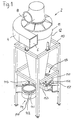
- the reference number 2 denotes a cyclone, the suction line 4 of which an inlet 6 connected via the interior of a powder coating booth, not shown is.
- a central outlet 8 of the cyclone is connected to a post-filter unit, also not shown Fan connected.
- the cyclone 2 is fixed in a stationary support frame 10.
- the Cyclone has an upper separation part 12 which is conical towards its lower end rejuvenated.
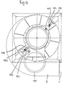
- the units 14, 15 are in the swung-out cleaning position removed from the cyclone shown, while in Figure 4 only the unit 14 in this cleaning position is shown while the unit 15 is in the operating position.
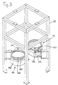
- Each unit 14, 15 has a screening device 141, 151 and a collecting funnel arranged underneath 142, 152, for excess powder separated in the separation part 12, which in the Powder cycle is to be returned.
- the units 14, 15 are pivotable about a pivot pin 143, 153, which in turn over a link 144, 154 is connected to a guide pin 145, 155 which is along one diagonally aligned to the cyclone degree guide 146, 156 is displaceable. This is on best seen in Fig. 4.
- the described pivoting movement is generated by the drive mentioned, for example by means of a fluid cylinder, which at point 147, 157 (FIG. 1) on the respective unit 14, 15 attacks, more precisely at their collecting funnels 142, 152.
- the already cleaned unit 15 is pivoted into the operating position in which it is pressed in alignment with the cyclone 2 on its underside, as in the figures 2 and 4 is shown. Now a new powder coating can be applied in the cabin Powder are started.
- the screening device 141 and the conveyor device 142 can be cleaned using a vacuum cleaner.
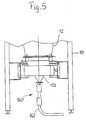
- the conveyor 160 and the delivery line 162 can be cleaned with a so-called pig, which goes into the delivery line can be introduced.
- This cleaning can be carried out more thoroughly than before, because it means there is no loss of time more associated with powder coating. In addition, there is still time for required maintenance work is available, for example for changing the screening device 141 or 151. The powder coating is done through this cleaning and / or maintenance in no way affected.
Abstract
Description
Die Erfindung betrifft ein Verfahren und eine Vorrichtung zur Pulverrückgewinnung bei der elektrostatischen Pulverbeschichtung.The invention relates to a method and an apparatus for powder recovery in the electrostatic powder coating.
Beim Pulverbeschichten von Werkstücken wird das Werkstück durch eine Kabine geführt und in dieser Kabine mit Pulver beschichtet. Dabei schlägt sich nicht das gesamte, durch die Applikationsgeräte in die Kabine geförderte Pulver auf dem Werkstück nieder, so daß sich ein Teil des Überschußpulvers auf dem Boden der Kabine ablagert.When powder coating workpieces, the workpiece is guided through a booth and powder coated in this cabin. Not all of this affects the application devices powder conveyed into the cabin on the workpiece, so that a Part of the excess powder is deposited on the floor of the cabin.
Bei bekannten Pulverbeschichtungsanlagen wird dieses Überschußpulver mittels einer technischen Lüftung aus der Kabine abgesaugt. Das nicht auf den Werkstücken abgelagerte Pulver wird üblicherweise wieder dem Prozeß zugeführt. Bei bekannten Pulverbeschichtungsanlagen wird dies mit einem oder mehreren Zyklonen realisiert. Dabei wird das Pulver aus dem Pulver-Luftgemisch im Zyklon getrennt und mit einer Fördervorrichtung wieder dem Prozeß zugeführt. Zusätzlich kann das Kreislaufpulver mittels einer Siebvorrichtung von Verunreinigungen befreit werden.In known powder coating systems, this excess powder is made by means of a technical Ventilation extracted from the cabin. The powder not deposited on the workpieces is usually returned to the process. In known powder coating systems this is realized with one or more cyclones. The powder is made from the powder-air mixture separated in the cyclone and returned to the process with a conveyor. In addition, the circuit powder can be contaminated by means of a sieving device be freed.
Vor einem Farbwechsel müssen alle Komponenten, die in Kontakt mit dem Beschichtungspulver kommen, einer Reinigung unterzogen werden. Um Farbverschleppungen zu vermeiden, die zu unbrauchbaren Beschichtungen führen würden, müssen insbesondere der Pulverauffangtrichter, die Siebvorrichtung sowie die Rückförderleitung zum Pulverbehälter für den erneuten Einsatz mit anderer Pulverfarbe einer gründlichen Reinigung unterzogen werden. Dies erfordert einen beachtlichen zeitlichen Aufwand.Before changing colors, all components that come into contact with the coating powder come to be subjected to cleaning. To avoid color spreading, that would lead to unusable coatings, the powder hopper in particular, the screening device and the return line to the powder container for the undergo thorough cleaning again when used with a different powder color. This requires a considerable amount of time.
Aufgabe der Erfindung ist es, ein Verfahren und eine Vorrichtung zu schaffen, welche einen schnelleren Farbwechsel erlauben und zudem eine gründlichere Reinigung ermöglichen. The object of the invention is to provide a method and an apparatus which one allow faster color changes and also enable more thorough cleaning.
Diese Aufgabe lösen eine Vorrichtung nach Anspruch 1 und ein Verfahren nach Anspruch 2.
Vorteilhafte Ausgestaltungen der Erfindung sind in den Unteransprüchen angegeben.This object is achieved by a device according to claim 1 and a method according to
Bei einer Vorrichtung gemäß der Erfindung hat der Zyklon einen Einlaß für das Pulver-Luftgemisch, ein Separationsteil, in dem das Pulver aus dem Pulver-Luftgemisch getrennt wird, eine Auffangvorrichtung, in der das Pulver aufgefangen wird, sowie eine Siebvorrichtung, die zwischen dem Separationsteil und dem Auffangtrichter angeordnet ist. Das in der Auffangvorrichtung angesammelte Pulver wird mit einer Fördereinrichtung über Leitungen wieder in den Pulverkreislauf des Prozesses zurückgeführt.In a device according to the invention, the cyclone has an inlet for the powder-air mixture, a separation part in which the powder is separated from the powder-air mixture a collecting device in which the powder is collected and a sieving device, which is arranged between the separation part and the collecting funnel. That in the Powder accumulated in the collecting device is conveyed by means of a conveyor returned to the powder cycle of the process.
Gemäß der Erfindung sind die Siebvorrichtung und die Auffangvorrichtung und vorteilhafterweise auch die Fördervorrichtung und die Förderleitung zu einer Einheit zusammengefaßt, die zwischen einer Betriebsposition und einer Reinigungsposition beweglich am Zyklon montiert ist. Diese Einheit ist zweifach vorgesehen.According to the invention, the screening device and the collecting device are and advantageously also the conveying device and the conveying line combined into one unit, moving between an operating position and a cleaning position on the cyclone is mounted. This unit is designed in two ways.
Bei einem Farbwechsel wird die erste Einheit aus der Betriebsposition geschwenkt. Während der Unterbrechung wird lediglich der obere Teil des Zyklons gereinigt. Danach wird die zweite Einheit mit Siebvorrichtung und Auffangvorrichtung, gegebenenfalls noch mit Fördervorrichtung sowie Leitungen, die in Reinigungsposition geparkt waren, in die Betriebsposition geschwenkt und mit einer Andrückvorrichtung (z. B. Pneumatikzylinder) an den unteren Teil des Zyklons gepreßt. Dadurch kann die zeitliche Unterbrechung der Pulverbeschichtung zwecks Reinigung vor einem Farbwechsel bedeutend reduziert werden.When changing colors, the first unit is swiveled out of the operating position. While during the interruption, only the upper part of the cyclone is cleaned. After that the second unit with screening device and collecting device, possibly also with conveyor device and lines that were parked in the cleaning position into the operating position pivoted and with a pressure device (e.g. pneumatic cylinder) on the lower Part of the cyclone pressed. This can interrupt the powder coating can be significantly reduced for cleaning before a color change.
Nun kann der Beschichtungsprozeß mit dem neuen Pulver gestartet werden. Die Siebvorrichtung, die Auffangvorrichtung, z. B. ein Auffangtrichter, und die Fördervorrichtung mit Leitungen der ersten Einheit werden nun in aller Ruhe gereinigt. Das Sieb und der Auffangtrichter können beispielsweise mit einem Sauger abgereinigt werden. Die Fördervorrichtung und speziell die Leitungen können mit einem sogenannten Molch gereinigt werden. Auf Grund des wegfallenden Zeitdruckes kann die Reinigung gründlicher durchgeführt werden. Zudem wird zusätzliche Zeit für eventuell nötige Wartungsarbeiten frei, z. B. für einen Siebwechsel, dies alles ohne Störung des Beschichtungsprozesses. Now the coating process with the new powder can be started. The screening device, the fall arrester, e.g. B. a collecting funnel, and the conveyor with lines the first unit are now cleaned in peace. The sieve and the collecting funnel can be cleaned with a vacuum, for example. The conveyor and especially the pipes can be cleaned with a so-called pig. Because of due to the lack of time pressure, cleaning can be carried out more thoroughly. moreover additional time is free for any necessary maintenance work, e.g. B. for a screen change, all without disturbing the coating process.
Die Erfindung ist im folgenden anhand von Zeichnungen an einem Ausführungsbeispiel mit weiteren Einzelheiten näher erläutert. Es zeigen:
- Fig. 1
- einen Zyklon mit zwei Einheiten mit Sieb und Auffangtrichter in ausgeschwenktem Zustand in perspektivischer Darstellung;
- Fig. 2
- eine Seitenansicht des Zyklons mit einer Einheit in Betriebszustand;
- Fig. 3
- in einer perspektivischen Darstellung wie in Fig. 1 die ausgeschwenkten Einheiten ohne Zyklongehäuse;
- Fig. 4
- in einer Ansicht von oben den Zyklon in einem Zustand gemäß Fig. 2 mit einer Einheit in Betriebsposition und der anderen Einheit in Reinigungsposition, und
- Fig. 5
- eine Seitenansicht des unteren Teils des Zyklons mit Fördervorrichtung und Förderleitung für das zurückgewonnene Pulver.
- Fig. 1
- a cyclone with two units with sieve and collecting funnel in the swung-out state in a perspective view;
- Fig. 2
- a side view of the cyclone with a unit in the operating state;
- Fig. 3
- in a perspective view as in Figure 1, the pivoted units without cyclone housing.
- Fig. 4
- in a view from above, the cyclone in a state according to FIG. 2 with one unit in the operating position and the other unit in the cleaning position, and
- Fig. 5
- a side view of the lower part of the cyclone with conveyor and conveyor line for the recovered powder.
In den Figuren ist mit der Bezugszahl 2 ein Zyklon bezeichnet, dessen Saugleitung 4 über
einen Einlaß 6 über den Innenraum einer nicht gezeigten Pulverbeschichtungskabine verbunden
ist.In the figures, the
Ein zentralerAuslaß 8 des Zyklons ist an eine ebenfalls nicht gezeigte Nachfiltereinheit mit
Gebläse angeschlossen. Der Zyklon 2 ist in einem ortsfesten Traggestell 10 befestigt. Der
Zyklon hat einen oberen Separationsteil 12, der sich zu seinem unteren Ende hin konisch
verjüngt.A
Unterhalb des Separationsteils 12 sind zwei gleichartige Einheiten 14, 15 schwenkbar am
Traggestell 10 so montiert, daß sie mittels eines nicht gezeigten Antriebes in Fluchtung und
Anpressung an die Unterseite des Zyklons geschwenkt werden können. Diese Betriebsposition
der Einheiten 14 und 15 ist in den Fig. 2, 4 und 5 dargestellt. Below the
In den Fig. 1 und 3 sind die Einheiten 14, 15 in ausgeschwenkter, vom Zyklon entfernter Reinigungsposition
dargestellt, während in Figur 4 nur die Einheit 14 in dieser Reinigungsposition
gezeigt ist, während sich die Einheit 15 in Betriebsposition befindet.1 and 3, the
Jede Einheit 14, 15 hat eine Siebvorrichtung 141, 151 und einen darunter angeordneten Auffangtrichter
142, 152, für im Seperationsteil 12 abgetrenntes Überschußpulver, das in den
Pulverkreislauf zurückzufördern ist.Each
Die Einheiten 14, 15 sind um einen Gelenkzapfen 143, 153 schwenkbar, der seinerseits über
einen Lenker 144, 154 mit einem Führungsstift 145, 155 verbunden ist, welcher längs einer
diagonal zum Zyklon ausgerichteten Gradführung 146, 156 verschieblich ist. Dies ist am
besten in Fig. 4 zu erkennen. Dort ist die eine Einheit 14 vom Zyklon weg in Reinigungsposition
geschwenkt, während die andere Einheit 15 in eine Betriebsposition geschwenkt ist, in
der die Einheit 15 mit dem Zyklon 2 fluchtend an dessen Unterseite angepreßt ist.The
Die geschilderte Schwenkbewegung wird durch den erwähnten Antrieb erzeugt, beispielsweise
durch einen Fluidzylinder, der am Punkt 147, 157 (Fig. 1) an der jeweiligen Einheit 14, 15
angreift, genauer gesagt an deren Auffangtrichter 142, 152.The described pivoting movement is generated by the drive mentioned, for example
by means of a fluid cylinder, which at
Der Betrieb ist nachfolgend geschildert. In der in Figur 1 dargestellten Stellung befinden sich
beide Einheiten 14, 15 in ausgeschwenkter Reinigungsposition. In dieser Reinigungsposition
ist die gebrauchte, durch Farbpartikel verschmutze Einheit 14 gerade in die Reinigungsposition
ausgeschwenkt, während die bereits gereinigte andere Einheit 15 noch nicht in die mit dem
Zyklon 2 fluchtende Betriebsposition eingeschwenkt ist. Während dieses Zustandes wird der
Separationsteil 12 des Zyklons von unten her gereinigt, beispielsweise durch Abblasen mittels
einer Düsenlanze mit Druckluft, oder durch AbsaugenThe operation is described below. In the position shown in Figure 1 are
both
Danach wird die bereits gereinigte Einheit 15 in die Betriebsposition eingeschwenkt, in welcher
sie mit dem Zyklon 2 fluchtend an dessen Unterseite angedrückt ist, wie dies in den Figuren
2 und 4 gezeigt ist. Nun kann erneut eine Pulverbeschichtung in der Kabine mit neuem
Pulver gestartet werden. Gleichzeitig können die Siebvorrichtung 141, der Auffangtrichter
142 und eine an das untere Ende des Auffangtrichters 142 angeschlossene Fördervorrichtung
160 mit Förderleitung 162 (Figur 5) für das zurückgewonnene und gesiebte Überschußpulver
in aller Ruhe gereinigt werden. Beispielsweise können die Siebvorrichtung 141 und die Fördervorrichtung
142 mittels eines Saugers abgereinigt werden. Die Fördervorrichtung 160 und
die Förderleitung 162 können mit einem sogenannten Molch gereinigt werden, der in die Förderleitung
einführbar ist.Then the already cleaned
Diese Reinigung kann gründlicher als bisher durchgeführt werden, weil damit kein Zeitausfall
mehr bei der Pulverbeschichtung verbunden ist. Überdies steht auch noch Zeit für eventuell
erforderliche Wartungsarbeiten zur Verfügung, beispielsweise für einen Wechsel der Siebvorrichtung
141 oder 151. Die Pulverbeschichtung wird durch diese Reinigungs- und/oder Wartungsarbeiten
in keiner Weise beeinflußt.This cleaning can be carried out more thoroughly than before, because it means there is no loss of time
more associated with powder coating. In addition, there is still time for
required maintenance work is available, for example for changing the
Anstatt schwenkbarer Einheiten 14, 15 könnten auch translatorisch bewegbare Einheiten vorgesehen
werden.Instead of
Die in der obigen Beschreibung, den Figuren und den Ansprüchen offenbarten Merkmale können sowohl einzeln als auch in beliebiger Kombination für die Verwirklichung der Erfindung von Bedeutung sein.The features disclosed in the above description, figures and claims can be used individually as well as in any combination for the implementation of the invention to be of importance.
Claims (9)
Priority Applications (1)
| Application Number | Priority Date | Filing Date | Title |
|---|---|---|---|
| EP01129868A EP1319442A1 (en) | 2001-12-14 | 2001-12-14 | Method and device for recovering powder in electrostatic powder coating |
Applications Claiming Priority (1)
| Application Number | Priority Date | Filing Date | Title |
|---|---|---|---|
| EP01129868A EP1319442A1 (en) | 2001-12-14 | 2001-12-14 | Method and device for recovering powder in electrostatic powder coating |
Publications (1)
| Publication Number | Publication Date |
|---|---|
| EP1319442A1 true EP1319442A1 (en) | 2003-06-18 |
Family
ID=8179558
Family Applications (1)
| Application Number | Title | Priority Date | Filing Date |
|---|---|---|---|
| EP01129868A Withdrawn EP1319442A1 (en) | 2001-12-14 | 2001-12-14 | Method and device for recovering powder in electrostatic powder coating |
Country Status (1)
| Country | Link |
|---|---|
| EP (1) | EP1319442A1 (en) |
Cited By (3)
| Publication number | Priority date | Publication date | Assignee | Title |
|---|---|---|---|---|
| EP3184178A1 (en) | 2015-12-23 | 2017-06-28 | J. Wagner AG | Powder coating equipment for coating workpieces |
| EP3335802A1 (en) | 2016-12-14 | 2018-06-20 | Wagner International Ag | Powder coating booth, powder coating installation and method for operating the powder coating booth |
| CN109569935A (en) * | 2018-12-28 | 2019-04-05 | 太仓联洲机械设备有限公司 | A kind of quick colour changing equipment of the willy-willy in electrostatic dusting room |
Citations (3)
| Publication number | Priority date | Publication date | Assignee | Title |
|---|---|---|---|---|
| DE4232382C1 (en) * | 1992-09-26 | 1994-03-24 | Pbs Pulverbeschichtungs Und Sp | Dust-separator with cyclone - has eddy-centring component secured by meshwork held at outlet edge and coarser than largest particle to be separated |
| DE19643965A1 (en) * | 1996-10-31 | 1998-05-07 | Gerhard Hestermann | Single electrostatic plastic powder coating spray booth,for various colour powders with over-spray powder recovery |
| US6080217A (en) * | 1997-05-13 | 2000-06-27 | Wagner International Ag | Device for separating excess powder oversprayed when powder coating workpieces |
-
2001
- 2001-12-14 EP EP01129868A patent/EP1319442A1/en not_active Withdrawn
Patent Citations (3)
| Publication number | Priority date | Publication date | Assignee | Title |
|---|---|---|---|---|
| DE4232382C1 (en) * | 1992-09-26 | 1994-03-24 | Pbs Pulverbeschichtungs Und Sp | Dust-separator with cyclone - has eddy-centring component secured by meshwork held at outlet edge and coarser than largest particle to be separated |
| DE19643965A1 (en) * | 1996-10-31 | 1998-05-07 | Gerhard Hestermann | Single electrostatic plastic powder coating spray booth,for various colour powders with over-spray powder recovery |
| US6080217A (en) * | 1997-05-13 | 2000-06-27 | Wagner International Ag | Device for separating excess powder oversprayed when powder coating workpieces |
Cited By (10)
| Publication number | Priority date | Publication date | Assignee | Title |
|---|---|---|---|---|
| EP3184178A1 (en) | 2015-12-23 | 2017-06-28 | J. Wagner AG | Powder coating equipment for coating workpieces |
| WO2017108198A3 (en) * | 2015-12-23 | 2017-08-10 | Wagner International Ag | Powder coating system for coating workpieces with coating powder |
| EP3184178B1 (en) | 2015-12-23 | 2018-10-17 | J. Wagner AG | Powder coating equipment for coating workpieces |
| US10751744B2 (en) | 2015-12-23 | 2020-08-25 | Wagner International Ag | Powder coating system for coating workpieces with coating powder |
| RU2733851C2 (en) * | 2015-12-23 | 2020-10-07 | Вагнер Интернэшнл Аг | Apparatus for applying powder for coating parts by powder coating |
| EP3335802A1 (en) | 2016-12-14 | 2018-06-20 | Wagner International Ag | Powder coating booth, powder coating installation and method for operating the powder coating booth |
| CN108212632A (en) * | 2016-12-14 | 2018-06-29 | 瓦格纳国际公司 | Powder coating cabin, powder coating facility and the method for operating the powder coating cabin |
| US10406550B2 (en) | 2016-12-14 | 2019-09-10 | Wagner International Ag | Powder coating booth, powder coating installation and method for operating the powder coating booth |
| CN108212632B (en) * | 2016-12-14 | 2021-11-19 | 瓦格纳国际公司 | Powder coating cabin, powder coating installation and method for operating the powder coating cabin |
| CN109569935A (en) * | 2018-12-28 | 2019-04-05 | 太仓联洲机械设备有限公司 | A kind of quick colour changing equipment of the willy-willy in electrostatic dusting room |
Similar Documents
| Publication | Publication Date | Title |
|---|---|---|
| EP0721804A2 (en) | Spray coating device | |
| DE69723992T2 (en) | METHOD AND DEVICE FOR A POWDER METALLURGICAL PROCESS | |
| DE4134701A1 (en) | POWDER SPRAY COATING DEVICE | |
| DE2318772A1 (en) | METHOD AND CABIN FOR ELECTROSTATIC POWDERING | |
| WO2014090207A1 (en) | Cleaning device for removing powder adhering to components or models | |
| DE2262084A1 (en) | DEVICE FOR POWDER RECOVERY, IN PARTICULAR IN EQUIPMENT FOR ELECTROSTATIC POWDER COATING | |
| EP0476169A1 (en) | Method of cleaning a cyclone and cyclone apt to be cleaned using this method | |
| DE3820931C2 (en) | Process for electrostatic surface discharge and dedusting of workpieces and device for carrying out the process | |
| DE2634250B2 (en) | Method and device for loading a card with fiber material | |
| EP3017933B1 (en) | Device for laser buildup welding for the additive manufacture of three-dimensional objects | |
| EP3880376B1 (en) | Method and apparatus for operating a metal printing device | |
| EP1319442A1 (en) | Method and device for recovering powder in electrostatic powder coating | |
| DE102010009069A1 (en) | Device for color powder coating of object, has powder squirting horizontal bar comprising area that is connected with after filter by bypassing cyclone arrangement, where arrangement is arranged downstream of after filter | |
| DE19500872B4 (en) | Powder spray coating apparatus | |
| EP0779107A1 (en) | Powder spray coating device | |
| AT407840B (en) | DEVICE FOR CLEANING HOSE FILTERS | |
| EP3718692A1 (en) | Method and device for finishing workpieces | |
| DE10054418A1 (en) | Air sifting granulates to clear impurities blows live air up through first hollow plate for first heavy impurities cut then on down to second contra-angled plate for second cut. | |
| DE102020108761B4 (en) | Device for cleaning 3D printed components | |
| DE3044655C2 (en) | Device for cleaning and hydraulic spraying of chocolate mass | |
| WO2007131752A1 (en) | Method for carrying out a cleaning process and device for carrying out said method | |
| DE4019555A1 (en) | Powder spray coating booth with modular main elements - permitting rapid substitution on colour changes | |
| EP0563081B1 (en) | Process for cleaning a drop separator and drop separator with cleaning device | |
| DE3716397C2 (en) | Cigarette manufacturing | |
| DE19824716B4 (en) | Pressing plant for the production of cup-shaped ceramic compacts |
Legal Events
| Date | Code | Title | Description |
|---|---|---|---|
| PUAI | Public reference made under article 153(3) epc to a published international application that has entered the european phase |
Free format text: ORIGINAL CODE: 0009012 |
|
| AK | Designated contracting states |
Designated state(s): AT BE CH CY DE DK ES FI FR GB GR IE IT LI LU MC NL PT SE TR |
|
| AX | Request for extension of the european patent |
Extension state: AL LT LV MK RO SI |
|
| 17P | Request for examination filed |
Effective date: 20031119 |
|
| AKX | Designation fees paid |
Designated state(s): CH DE IT LI |
|
| 17Q | First examination report despatched |
Effective date: 20040301 |
|
| STAA | Information on the status of an ep patent application or granted ep patent |
Free format text: STATUS: THE APPLICATION IS DEEMED TO BE WITHDRAWN |
|
| 18D | Application deemed to be withdrawn |
Effective date: 20040713 |