EP1318399A2 - Passive Probefeststellung zum Beginn einer Analyse - Google Patents
Passive Probefeststellung zum Beginn einer Analyse Download PDFInfo
- Publication number
- EP1318399A2 EP1318399A2 EP02258481A EP02258481A EP1318399A2 EP 1318399 A2 EP1318399 A2 EP 1318399A2 EP 02258481 A EP02258481 A EP 02258481A EP 02258481 A EP02258481 A EP 02258481A EP 1318399 A2 EP1318399 A2 EP 1318399A2
- Authority
- EP
- European Patent Office
- Prior art keywords
- sample
- electrochemical cell
- analyte
- electrodes
- potential difference
- Prior art date
- Legal status (The legal status is an assumption and is not a legal conclusion. Google has not performed a legal analysis and makes no representation as to the accuracy of the status listed.)
- Withdrawn
Links
- 238000001514 detection method Methods 0.000 title claims abstract description 60
- 238000003556 assay Methods 0.000 title description 14
- 238000000034 method Methods 0.000 claims abstract description 75
- 239000000523 sample Substances 0.000 claims description 108
- 239000012491 analyte Substances 0.000 claims description 80
- 238000012360 testing method Methods 0.000 claims description 65
- 102000004190 Enzymes Human genes 0.000 claims description 30
- 108090000790 Enzymes Proteins 0.000 claims description 30
- 239000012472 biological sample Substances 0.000 claims description 14
- 238000000840 electrochemical analysis Methods 0.000 claims description 12
- 239000000126 substance Substances 0.000 claims description 11
- 230000004044 response Effects 0.000 claims description 8
- 238000003487 electrochemical reaction Methods 0.000 claims description 7
- 238000012544 monitoring process Methods 0.000 claims description 5
- 238000000151 deposition Methods 0.000 claims description 3
- 238000004891 communication Methods 0.000 claims description 2
- 238000005259 measurement Methods 0.000 abstract description 58
- 230000000977 initiatory effect Effects 0.000 abstract description 7
- 210000004027 cell Anatomy 0.000 description 53
- 239000003153 chemical reaction reagent Substances 0.000 description 31
- 229940088598 enzyme Drugs 0.000 description 25
- 238000006243 chemical reaction Methods 0.000 description 18
- 210000004369 blood Anatomy 0.000 description 12
- 239000008280 blood Substances 0.000 description 12
- 230000006870 function Effects 0.000 description 11
- 239000000463 material Substances 0.000 description 11
- WQZGKKKJIJFFOK-GASJEMHNSA-N Glucose Natural products OC[C@H]1OC(O)[C@H](O)[C@@H](O)[C@@H]1O WQZGKKKJIJFFOK-GASJEMHNSA-N 0.000 description 8
- 239000008103 glucose Substances 0.000 description 8
- 125000006850 spacer group Chemical group 0.000 description 8
- WQZGKKKJIJFFOK-VFUOTHLCSA-N beta-D-glucose Chemical compound OC[C@H]1O[C@@H](O)[C@H](O)[C@@H](O)[C@@H]1O WQZGKKKJIJFFOK-VFUOTHLCSA-N 0.000 description 7
- YAGKRVSRTSUGEY-UHFFFAOYSA-N ferricyanide Chemical compound [Fe+3].N#[C-].N#[C-].N#[C-].N#[C-].N#[C-].N#[C-] YAGKRVSRTSUGEY-UHFFFAOYSA-N 0.000 description 7
- 230000008901 benefit Effects 0.000 description 6
- KDLHZDBZIXYQEI-UHFFFAOYSA-N Palladium Chemical compound [Pd] KDLHZDBZIXYQEI-UHFFFAOYSA-N 0.000 description 4
- HVYWMOMLDIMFJA-DPAQBDIFSA-N cholesterol Chemical compound C1C=C2C[C@@H](O)CC[C@]2(C)[C@@H]2[C@@H]1[C@@H]1CC[C@H]([C@H](C)CCCC(C)C)[C@@]1(C)CC2 HVYWMOMLDIMFJA-DPAQBDIFSA-N 0.000 description 4
- MMXZSJMASHPLLR-UHFFFAOYSA-N pyrroloquinoline quinone Chemical compound C12=C(C(O)=O)C=C(C(O)=O)N=C2C(=O)C(=O)C2=C1NC(C(=O)O)=C2 MMXZSJMASHPLLR-UHFFFAOYSA-N 0.000 description 4
- 239000012488 sample solution Substances 0.000 description 4
- 238000000970 chrono-amperometry Methods 0.000 description 3
- 238000003869 coulometry Methods 0.000 description 3
- -1 e.g. Substances 0.000 description 3
- 238000002848 electrochemical method Methods 0.000 description 3
- 230000008569 process Effects 0.000 description 3
- ZYDGCYWJDWIJCS-UHFFFAOYSA-N 1-methoxyphenazine Chemical compound C1=CC=C2N=C3C(OC)=CC=CC3=NC2=C1 ZYDGCYWJDWIJCS-UHFFFAOYSA-N 0.000 description 2
- 108010050375 Glucose 1-Dehydrogenase Proteins 0.000 description 2
- 108010015776 Glucose oxidase Proteins 0.000 description 2
- 239000004366 Glucose oxidase Substances 0.000 description 2
- BAWFJGJZGIEFAR-NNYOXOHSSA-N NAD zwitterion Chemical compound NC(=O)C1=CC=C[N+]([C@H]2[C@@H]([C@H](O)[C@@H](COP([O-])(=O)OP(O)(=O)OC[C@@H]3[C@H]([C@@H](O)[C@@H](O3)N3C4=NC=NC(N)=C4N=C3)O)O2)O)=C1 BAWFJGJZGIEFAR-NNYOXOHSSA-N 0.000 description 2
- 108090000854 Oxidoreductases Proteins 0.000 description 2
- 102000004316 Oxidoreductases Human genes 0.000 description 2
- 239000004642 Polyimide Substances 0.000 description 2
- 239000013060 biological fluid Substances 0.000 description 2
- 239000000872 buffer Substances 0.000 description 2
- 239000003795 chemical substances by application Substances 0.000 description 2
- 235000012000 cholesterol Nutrition 0.000 description 2
- 238000004769 chrono-potentiometry Methods 0.000 description 2
- 239000011248 coating agent Substances 0.000 description 2
- 238000000576 coating method Methods 0.000 description 2
- 239000004020 conductor Substances 0.000 description 2
- 230000008021 deposition Effects 0.000 description 2
- 238000010586 diagram Methods 0.000 description 2
- KTWOOEGAPBSYNW-UHFFFAOYSA-N ferrocene Chemical class [Fe+2].C=1C=C[CH-]C=1.C=1C=C[CH-]C=1 KTWOOEGAPBSYNW-UHFFFAOYSA-N 0.000 description 2
- 239000012530 fluid Substances 0.000 description 2
- 229940116332 glucose oxidase Drugs 0.000 description 2
- 235000019420 glucose oxidase Nutrition 0.000 description 2
- 125000002791 glucosyl group Chemical group C1([C@H](O)[C@@H](O)[C@H](O)[C@H](O1)CO)* 0.000 description 2
- PCHJSUWPFVWCPO-UHFFFAOYSA-N gold Chemical compound [Au] PCHJSUWPFVWCPO-UHFFFAOYSA-N 0.000 description 2
- 229910052737 gold Inorganic materials 0.000 description 2
- 239000010931 gold Substances 0.000 description 2
- 238000005534 hematocrit Methods 0.000 description 2
- 238000007726 management method Methods 0.000 description 2
- 229910052751 metal Inorganic materials 0.000 description 2
- 239000002184 metal Substances 0.000 description 2
- 238000012986 modification Methods 0.000 description 2
- 230000004048 modification Effects 0.000 description 2
- 238000004806 packaging method and process Methods 0.000 description 2
- 229910052763 palladium Inorganic materials 0.000 description 2
- 239000004033 plastic Substances 0.000 description 2
- 229920003023 plastic Polymers 0.000 description 2
- BASFCYQUMIYNBI-UHFFFAOYSA-N platinum Chemical compound [Pt] BASFCYQUMIYNBI-UHFFFAOYSA-N 0.000 description 2
- 229920000515 polycarbonate Polymers 0.000 description 2
- 239000004417 polycarbonate Substances 0.000 description 2
- 229920000139 polyethylene terephthalate Polymers 0.000 description 2
- 229920005644 polyethylene terephthalate glycol copolymer Polymers 0.000 description 2
- 229920001721 polyimide Polymers 0.000 description 2
- 229910052709 silver Inorganic materials 0.000 description 2
- 238000003860 storage Methods 0.000 description 2
- 239000000758 substrate Substances 0.000 description 2
- 230000001052 transient effect Effects 0.000 description 2
- LNXVNZRYYHFMEY-UHFFFAOYSA-N 2,5-dichlorocyclohexa-2,5-diene-1,4-dione Chemical compound ClC1=CC(=O)C(Cl)=CC1=O LNXVNZRYYHFMEY-UHFFFAOYSA-N 0.000 description 1
- SENUUPBBLQWHMF-UHFFFAOYSA-N 2,6-dimethylcyclohexa-2,5-diene-1,4-dione Chemical compound CC1=CC(=O)C=C(C)C1=O SENUUPBBLQWHMF-UHFFFAOYSA-N 0.000 description 1
- LJCNDNBULVLKSG-UHFFFAOYSA-N 2-aminoacetic acid;butane Chemical compound CCCC.CCCC.NCC(O)=O LJCNDNBULVLKSG-UHFFFAOYSA-N 0.000 description 1
- VDJKJPMLWJWQIH-UHFFFAOYSA-M 5-ethylphenazin-5-ium;ethyl sulfate Chemical compound CCOS([O-])(=O)=O.C1=CC=C2[N+](CC)=C(C=CC=C3)C3=NC2=C1 VDJKJPMLWJWQIH-UHFFFAOYSA-M 0.000 description 1
- RXGJTUSBYWCRBK-UHFFFAOYSA-M 5-methylphenazinium methyl sulfate Chemical compound COS([O-])(=O)=O.C1=CC=C2[N+](C)=C(C=CC=C3)C3=NC2=C1 RXGJTUSBYWCRBK-UHFFFAOYSA-M 0.000 description 1
- 108010025188 Alcohol oxidase Proteins 0.000 description 1
- 108010024957 Ascorbate Oxidase Proteins 0.000 description 1
- 108010015428 Bilirubin oxidase Proteins 0.000 description 1
- OKTJSMMVPCPJKN-UHFFFAOYSA-N Carbon Chemical compound [C] OKTJSMMVPCPJKN-UHFFFAOYSA-N 0.000 description 1
- 108010089254 Cholesterol oxidase Proteins 0.000 description 1
- KRKNYBCHXYNGOX-UHFFFAOYSA-K Citrate Chemical compound [O-]C(=O)CC(O)(CC([O-])=O)C([O-])=O KRKNYBCHXYNGOX-UHFFFAOYSA-K 0.000 description 1
- 108020005199 Dehydrogenases Proteins 0.000 description 1
- 108090000371 Esterases Proteins 0.000 description 1
- 108700016170 Glycerol kinases Proteins 0.000 description 1
- 102000057621 Glycerol kinases Human genes 0.000 description 1
- 108090000604 Hydrolases Proteins 0.000 description 1
- 102000004157 Hydrolases Human genes 0.000 description 1
- 102000003855 L-lactate dehydrogenase Human genes 0.000 description 1
- 108700023483 L-lactate dehydrogenases Proteins 0.000 description 1
- 108010073450 Lactate 2-monooxygenase Proteins 0.000 description 1
- 108010013563 Lipoprotein Lipase Proteins 0.000 description 1
- 102100022119 Lipoprotein lipase Human genes 0.000 description 1
- 229910019142 PO4 Inorganic materials 0.000 description 1
- 108700020962 Peroxidase Proteins 0.000 description 1
- 102000003992 Peroxidases Human genes 0.000 description 1
- 239000004793 Polystyrene Substances 0.000 description 1
- 108010042687 Pyruvate Oxidase Proteins 0.000 description 1
- KJTLSVCANCCWHF-UHFFFAOYSA-N Ruthenium Chemical compound [Ru] KJTLSVCANCCWHF-UHFFFAOYSA-N 0.000 description 1
- 108010060059 Sarcosine Oxidase Proteins 0.000 description 1
- 102000008118 Sarcosine oxidase Human genes 0.000 description 1
- 229910021607 Silver chloride Inorganic materials 0.000 description 1
- 102000000019 Sterol Esterase Human genes 0.000 description 1
- 108010055297 Sterol Esterase Proteins 0.000 description 1
- 102000004357 Transferases Human genes 0.000 description 1
- 108090000992 Transferases Proteins 0.000 description 1
- 108010092464 Urate Oxidase Proteins 0.000 description 1
- 239000000853 adhesive Substances 0.000 description 1
- 230000001070 adhesive effect Effects 0.000 description 1
- 238000004458 analytical method Methods 0.000 description 1
- 238000013459 approach Methods 0.000 description 1
- 238000010420 art technique Methods 0.000 description 1
- 230000009286 beneficial effect Effects 0.000 description 1
- 239000012620 biological material Substances 0.000 description 1
- 239000006172 buffering agent Substances 0.000 description 1
- 229910052799 carbon Inorganic materials 0.000 description 1
- 239000000919 ceramic Substances 0.000 description 1
- 230000008859 change Effects 0.000 description 1
- 229940018560 citraconate Drugs 0.000 description 1
- HNEGQIOMVPPMNR-IHWYPQMZSA-N citraconic acid Chemical compound OC(=O)C(/C)=C\C(O)=O HNEGQIOMVPPMNR-IHWYPQMZSA-N 0.000 description 1
- 230000002596 correlated effect Effects 0.000 description 1
- 230000000875 corresponding effect Effects 0.000 description 1
- 230000007423 decrease Effects 0.000 description 1
- 230000003247 decreasing effect Effects 0.000 description 1
- 206010012601 diabetes mellitus Diseases 0.000 description 1
- 238000003745 diagnosis Methods 0.000 description 1
- 201000010099 disease Diseases 0.000 description 1
- 208000037265 diseases, disorders, signs and symptoms Diseases 0.000 description 1
- 230000002526 effect on cardiovascular system Effects 0.000 description 1
- 238000007812 electrochemical assay Methods 0.000 description 1
- 239000007772 electrode material Substances 0.000 description 1
- 230000008030 elimination Effects 0.000 description 1
- 238000003379 elimination reaction Methods 0.000 description 1
- 230000007613 environmental effect Effects 0.000 description 1
- 210000003743 erythrocyte Anatomy 0.000 description 1
- 239000011521 glass Substances 0.000 description 1
- 229930195712 glutamate Natural products 0.000 description 1
- 108010054790 glycerol-3-phosphate oxidase Proteins 0.000 description 1
- 238000011065 in-situ storage Methods 0.000 description 1
- AMGQUBHHOARCQH-UHFFFAOYSA-N indium;oxotin Chemical compound [In].[Sn]=O AMGQUBHHOARCQH-UHFFFAOYSA-N 0.000 description 1
- 230000010354 integration Effects 0.000 description 1
- 229910052741 iridium Inorganic materials 0.000 description 1
- GKOZUEZYRPOHIO-UHFFFAOYSA-N iridium atom Chemical compound [Ir] GKOZUEZYRPOHIO-UHFFFAOYSA-N 0.000 description 1
- 230000001788 irregular Effects 0.000 description 1
- 238000002372 labelling Methods 0.000 description 1
- 239000007788 liquid Substances 0.000 description 1
- 238000000691 measurement method Methods 0.000 description 1
- 150000002739 metals Chemical class 0.000 description 1
- 229950006238 nadide Drugs 0.000 description 1
- 229910052759 nickel Inorganic materials 0.000 description 1
- 150000002907 osmium Chemical class 0.000 description 1
- 229910052762 osmium Inorganic materials 0.000 description 1
- 230000001590 oxidative effect Effects 0.000 description 1
- 125000001484 phenothiazinyl group Chemical class C1(=CC=CC=2SC3=CC=CC=C3NC12)* 0.000 description 1
- 125000001644 phenoxazinyl group Chemical class C1(=CC=CC=2OC3=CC=CC=C3NC12)* 0.000 description 1
- NBIIXXVUZAFLBC-UHFFFAOYSA-K phosphate Chemical compound [O-]P([O-])([O-])=O NBIIXXVUZAFLBC-UHFFFAOYSA-K 0.000 description 1
- 239000010452 phosphate Substances 0.000 description 1
- IEQIEDJGQAUEQZ-UHFFFAOYSA-N phthalocyanine Chemical class N1C(N=C2C3=CC=CC=C3C(N=C3C4=CC=CC=C4C(=N4)N3)=N2)=C(C=CC=C2)C2=C1N=C1C2=CC=CC=C2C4=N1 IEQIEDJGQAUEQZ-UHFFFAOYSA-N 0.000 description 1
- 229910052697 platinum Inorganic materials 0.000 description 1
- 229920000728 polyester Polymers 0.000 description 1
- 229920002223 polystyrene Polymers 0.000 description 1
- 238000006479 redox reaction Methods 0.000 description 1
- 150000003303 ruthenium Chemical class 0.000 description 1
- 229910052707 ruthenium Inorganic materials 0.000 description 1
- 210000003296 saliva Anatomy 0.000 description 1
- 239000004065 semiconductor Substances 0.000 description 1
- 229910052710 silicon Inorganic materials 0.000 description 1
- 239000010703 silicon Substances 0.000 description 1
- HKZLPVFGJNLROG-UHFFFAOYSA-M silver monochloride Chemical compound [Cl-].[Ag+] HKZLPVFGJNLROG-UHFFFAOYSA-M 0.000 description 1
- 238000004544 sputter deposition Methods 0.000 description 1
- 229910001220 stainless steel Inorganic materials 0.000 description 1
- 239000010935 stainless steel Substances 0.000 description 1
- 230000003068 static effect Effects 0.000 description 1
- 229940066767 systemic antihistamines phenothiazine derivative Drugs 0.000 description 1
- 210000001138 tear Anatomy 0.000 description 1
- 230000001960 triggered effect Effects 0.000 description 1
- 238000013024 troubleshooting Methods 0.000 description 1
- 210000002700 urine Anatomy 0.000 description 1
- 229910052725 zinc Inorganic materials 0.000 description 1
Images


Classifications
-
- G—PHYSICS
- G01—MEASURING; TESTING
- G01N—INVESTIGATING OR ANALYSING MATERIALS BY DETERMINING THEIR CHEMICAL OR PHYSICAL PROPERTIES
- G01N33/00—Investigating or analysing materials by specific methods not covered by groups G01N1/00 - G01N31/00
- G01N33/48—Biological material, e.g. blood, urine; Haemocytometers
- G01N33/483—Physical analysis of biological material
- G01N33/487—Physical analysis of biological material of liquid biological material
-
- G—PHYSICS
- G01—MEASURING; TESTING
- G01N—INVESTIGATING OR ANALYSING MATERIALS BY DETERMINING THEIR CHEMICAL OR PHYSICAL PROPERTIES
- G01N27/00—Investigating or analysing materials by the use of electric, electrochemical, or magnetic means
- G01N27/26—Investigating or analysing materials by the use of electric, electrochemical, or magnetic means by investigating electrochemical variables; by using electrolysis or electrophoresis
- G01N27/28—Electrolytic cell components
- G01N27/30—Electrodes, e.g. test electrodes; Half-cells
- G01N27/327—Biochemical electrodes, e.g. electrical or mechanical details for in vitro measurements
- G01N27/3271—Amperometric enzyme electrodes for analytes in body fluids, e.g. glucose in blood
- G01N27/3273—Devices therefor, e.g. test element readers, circuitry
Definitions
- the present invention relates to the field of electrochemical assays, particularly to the measurement of the concentration of analytes in biological fluid. More particularly, the present invention relates to a system and method for detecting the application of a sample of biological or control fluid to an electrochemical sensor and initiating the timing of the analyte measurement event.
- Analyte concentration determination in biological fluids is of ever increasing importance to today's society.
- Such assays find use in a variety of applications and settings, including clinical laboratory testing, home testing, etc., where the results of such testing play a prominent role in the diagnosis and management of a variety of disease conditions.
- Common analytes of interest include glucose for diabetes management, cholesterol for monitoring cardiovascular conditions, and the like.
- analyte detection protocols and devices for both clinical and home use have been developed.
- One type of method that is employed for analyte detection is an electrochemical-based method.
- a sample of a substance to be tested e.g., a biological substance typically in aqueous liquid form, e.g., blood
- an electrochemical cell made up of at least two electrodes, i.e., a counter/reference electrode and a working electrode.
- a redox reagent system is present within the reaction zone.
- a reagent system includes at least an enzyme(s) and a mediator.
- the enzyme member(s) of the redox reagent system is an enzyme or plurality of enzymes that work in concert to specifically oxidize/reduce the analyte of interest.
- the targeted analyte comes into contact with the enzyme(s) and reacts there with forming an oxidisable (or reducible) inactive enzyme.
- It is a mediator's role to react with an oxidisable (or reducible) enzyme generating a fully active enzyme and a substance, i.e ., the product of the reaction between the inactive enzyme and the mediator, in an amount corresponding to the concentration of the targeted analyte.
- the quantity of the oxidisable (or reducible) substance present is then estimated electrochemically and correlated to the amount of analyte present in the initial biological substance.
- electrochemical cell is commonly used in the form of a disposable test strip on which the biological sample is deposited and which is receivable within a meter by which the electrochemical analyte concentration is determined.
- assay systems that employ these types of test strips, often referred to as biosensors, and meters may be found in U.S. Patent Nos. 5,942,102, 6,174,420 B1 and 6,179,979 B1, the disclosures of which are herein incorporated by reference.
- These systems can be characterized as coulometric, amperometric or potentiometric, depending on whether the system involves measuring charge, current or potential, respectively, in making the analyte concentration determination.
- the measurement system In electrochemical analyte measurement assays, it is necessary that the measurement system be able to detect the presence of a sample deposited onto a test strip so that the analyte concentration measurement test may be initiated. Moreover, it is important that the presence of sample be detected as soon as the sample comes into contact with the reagent system of the test strip. The timeliness of this detection is important in order to minimize the potential for perturbation of the electrochemical reaction between the target analyte and the reagent system. Perturbation is a change in the equilibrium of the electrochemical cell's reagent system caused by other than the normal and expected reaction progress of the target analyte with the reagent system mediator and enzyme components.
- Perturbation is a particularly problematic with amperometric sample detection methodologies, known as "chronoamperometry," which are employed in electrochemical analyte concentration determination methods, and most commonly employed in chronoamperometric assays of an analyte concentration.
- chronoamperometry amperometric sample detection methodologies, known as "chronoamperometry," which are employed in electrochemical analyte concentration determination methods, and most commonly employed in chronoamperometric assays of an analyte concentration.
- chronoamperometry amperometric sample detection methodologies, known as "chronoamperometry”
- a constant-voltage step function is applied to the test strip, i.e., across the working and reference electrodes, which, upon sample application to the test strip, results in generation of a current through the electrochemical cell of the test strip.
- the magnitude of the applied voltage must be sufficient to trigger the Faradaic or capacitance current flow in the cell to provide rapid sample detection.
- the system i.e ., the meter
- the system "stamps" this time as the beginning of the analyte concentration measurement phase, and thus, initiates measurement of the current at the working electrode to determine the concentration of the targeted analyte.
- the electrochemical reaction between the redox reagent system and the biological sample is initiated prior to the system being ready to accurately stamp or mark the actual time of initiation of the analyte concentration measurement phase.
- a fraction of the current produced as a result of this electrochemical reaction is used as part of the sample detection phase.
- the finally measured current is not an accurate representation of the analyte concentration of the sample.
- the voltage applied to the cell will "perturb" the electrochemical reaction between the target analyte and the reagents.
- the electronic circuitry which provides both a current source for the supply of the constant-current step function to the reagent test strip for performing the sample detection phase, as well as a voltage source for performing the analyte concentration measurement phase of the method.
- the electronic circuitry further includes the necessary components to allow switching from the application of the current supply to application of the voltage supply at the precise time that the sample detection phase is complete.
- sample detection phase detecting the presence of a sample applied to a biosensor
- concentration of one or more analytes of the sample
- prior art methods of sample detection involve application of an electrical input signal, either a voltage step function (as with chronoamperometry) or a current step function (as with chronopotentiometry), prior to placement of the biological sample within the electrochemical cell.
- an electrical input signal either a voltage step function (as with chronoamperometry) or a current step function (as with chronopotentiometry)
- the measurement phase is not commenced until a threshold level is achieved by the electrical signal produced, a current signal or a voltage signal, respectively, as a result of the application of the electrical input signal.
- the subject methods do not employ or involve the application of an electrical signal from an external source to the electrochemical cell for purposes of performing the sample detection phase.
- this phase is commenced passively, solely by placement of a sample within the electrochemical cell, thereby bridging the gap between the electrodes and generating a signal, i.e., a voltage signal.
- a signal i.e., a voltage signal.
- the sample detection time is noted or recorded, and a measurement related electrical signal, i.e., a voltage signal, is automatically applied across the electrochemical cell for purposes of testing the sample for a selected characteristic.
- a measurement related electrical signal i.e., a voltage signal
- the resulting current response is measured. From this measured current, or its integration over time, the analyte concentration is then calculated.
- the subject methods provide significant advantages over prior art methods for sample detection. Because there is no external electrical signal applied to the sample prior to the measurement phase, the sample detection phase of the subject methods does not create any perturbation of the sample. Thus, the value of the resulting output signal from the measurement phase represents only the amount (e.g., volume, percentage, etc.) of the characteristic of the sample being measured, a far more accurate measurement than what is provided by many prior art methods.
- Another advantage of the present invention is the elimination of false or inaccurate analyte measurements due to damaged or mishandled electrodes.
- any damage e.g., a short circuit
- an assay can only be initiated upon deposit of the sample solution within the electrochemical cell of the biosensor.
- the systems of the present invention include electronic circuitry and components that may be incorporated or provided integrally with a meter for receiving a biosensor, such as an electrochemical test strip to which the sample volume of biological solution is deposited, for purposes of measuring a selected characteristic, e.g ., the concentration of selected analytes of interest, of the sample.
- the electrochemical test strip includes an electrochemical cell comprised of at least two electrodes, i.e ., a working and a reference/counter electrode, between which a reaction zone is defined for receiving the biological sample.
- kits which include test strip meters which incorporate the subject systems for practicing the subject methods.
- While the subject methods, systems and kits may be used to detect different types of biological samples, such as blood, urine, tears, saliva, and the like, applied to various types of electrochemical cells for the measurement of various characteristics, such as analyte concentrations, they are particularly well suited for the detection of samples of blood or blood fractions and the like as applied to the electrochemical cell of a test strip for the determination of glucose concentration therein.
- biological samples such as blood, urine, tears, saliva, and the like
- electrochemical cells for the measurement of various characteristics, such as analyte concentrations
- Fig. 1 is an exploded view of an electrochemical test strip for use with the present invention.
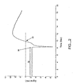
- Fig. 2 is a graph of the voltage profile across an electrochemical test strip vs. time for the method of the present invention.
- Fig. 3 is a schematic diagram of an electronic circuit of a system of the present invention operatively coupled to an electrochemical biosensor for practicing the subject method.
- the present invention provides methods and systems for automatically detecting the presence of a sample applied to a biosensor (the “sample detection phase”) and then initiating the measurement of a targeted characteristic, e.g. , the concentration of one or more analytes, of the sample (the “measurement phase") immediately upon sample detection.
- the sample detection phase of the subject methods is performed passively, immediately upon application of a sample to a biosensor, without application of a voltage step function (as with chronoamperometry) or current step function (as with chronopotentiometry).
- the subject systems include electronic circuitry for performing these steps.
- kits that include a test strip meter which incorporate the subject systems for practicing the subject methods.
- the subject methods and systems are usable with a biosensor, more particularly an electrochemical cell-based biosensor, into which the sampled biological material is deposited or transferred.
- a biosensor more particularly an electrochemical cell-based biosensor, into which the sampled biological material is deposited or transferred.
- electrochemical cell-based biosensors There are varying designs of electrochemical cell-based biosensors. The most common of these designs employed in the field of analyte concentration monitoring include test strip configurations, such as those disclosed in U.S. Patent No. 6,193,873, EP-A-1 252 514, EP-A-1 254 365, WO02/48707 and WO02/50609.
- test strips are used with meters configured for electrochemical measurements, such as those disclosed in the above-identified patent references.
- Electrochemical biosensors other than test strips may also be suitable for use with the present invention.
- the electrochemical cell may have a cylindrical configuration wherein a core electrode is co-axially positioned within a second tubular electrode.
- Such electrochemical cell configurations may be in the form of micro-needles and, as such, are either integral within the needle structure for in situ ( e.g ., typically under the skin surface) measurements or otherwise in physical or fluid communication with a micro-needle structure. Examples of such micro-needle are disclosed in EP-A-1 266 607 and EP-A-1 266 625.
- the subject devices will be described in use with electrochemical cells in test strip configurations; however, those skilled in the art will appreciate that the subject devices may be used with any suitable electrochemical cell configuration, including micro-needle configurations.
- the type of electrochemical measurement that is made may vary depending on the particular nature of the assay and the meter with which the electrochemical test strip is employed, e.g. , depending on whether the assay is coulometric, amperometric or potentiometric.
- the electrochemical cell will measure charge in a coulometric assay, current in an amperometric assay and potential in a potentiometric assay.
- the present invention will be described in the context of amperometric assays; however, the subject devices may be employed with any type of assay and electrochemical measurement.
- an electrochemical cell includes at least two electrodes, a working and a reference/counter electrode, spaced-apart in either a facing arrangement or in a side-by-side arrangement in the same plane.
- the electrodes are separated by a thin spacer layer, which defines a reaction area or zone, or chamber into which a biological sample is deposited or transferred for analyte concentration measurement.
- the electrodes are in a chamber with a defined thickness and volume.
- electrochemical cells can have two or more electrodes, i.e., one working electrode and one counter/reference electrode, one working electrode and one counter electrode and one reference electrode, two working electrodes and one counter/reference electrode, etc. Depending on the type of application, it may be more desirable to have more than two electrodes in the electrochemical cell to allow for a more accurate voltage application or perhaps for measuring more than one analyte.
- Test strip 10 is made up of a bottom layer 12 and a top layer 24 separated by a thin spacer layer 20 which has a cutaway section that defines a reaction zone or area 22.
- bottom and top layers 12 and 24 are configured in the form of elongated rectangular strips each having a length in the range from about 2 to 6 cm, usually from about 3 to 4 cm, having a width in the range from about 0.3 to 1.0 cm, usually from about 0.5 to 0.7 cm, and having a thickness in the range from about 0.2 to 1.2 mm, and usually from 0.38 to 0.64 mm.
- Bottom layers 12 and 24 each define a substrate base, 14 and 26, respectively, made of an inert support or backing material on which has been deposited, typically by sputtering, a conductive material which form the reference and working electrodes, 16 and 28, respectively.
- the inert backing material is typically rigid material and capable of providing structural support to each of the electrodes 16 and 28 and, in turn, the electrochemical test strip as a whole.
- suitable materials include plastics (e.g. , PET, PETG, polyimide, polycarbonate, polystyrene, polyester), silicon, ceramic, glass, and the like.
- the conductive material is preferably a metal, where metals of interest include palladium, gold, platinum, iridium, doped indium tin oxide, stainless steel, carbon and the like.
- metals of interest include palladium, gold, platinum, iridium, doped indium tin oxide, stainless steel, carbon and the like.
- a palladium coating may form working electrode 16 while a gold coating forms reference electrode 28.
- Spacer layer 20 is positioned or sandwiched between electrodes 16 and 28.
- the thickness of spacer layer 12 generally ranges from about 1 to 500 ⁇ m, and usually from about 50 to 150 ⁇ m.
- Spacer layer 20 may be fabricated from any convenient material, where representative suitable materials include PET, PETG, polyimide, polycarbonate and the like. The surfaces of spacer layer 20 may be treated so as to be adhesive with respective electrodes 16 and 28 and thereby maintain the structure of the electrochemical test strip 10.
- Spacer layer 20 is cut so as to provide a reaction zone or area 22 having any appropriate shape including circular, square, triangular, rectangular, or irregular shaped reaction areas.
- the top and bottom of the reaction zone 22 is defined by the facing surfaces of electrodes 16, 28 while spacer layer 20 defines the sidewalls of the reaction area 22.
- the volume of the reaction area ranges from at least about 0.1 to 10 ⁇ l, usually from about 0.2 to 5.0 ⁇ L and more usually from about 0.05 to 1.6 ⁇ L.
- a redox reagent system Present in the reaction area 22, deposited near one end 18 of electrode 16, is a redox reagent system, generally referred to as a signal producing system, which provides for the specific reagent components that chemically interact with the target analyte to derive the concentration of analyte in the biological sample.
- the redox reagent system or signal producing system typically includes at least one enzyme component and a mediator component.
- the enzyme component includes one or more enzymes that work in concert to oxidize/reduce the analyte of interest.
- the enzyme component of the redox reagent system is made up of a single analyte oxidizing/reducing enzyme or a collection of two or more enzymes that work in concert to oxidize/reduce the analyte of interest.
- Typical enzymes of interest include oxidoreductases, hydrolases, transferases, dehydrogenases, esterases, and the like; however, the specific enzyme present in the reaction area depends on the particular analyte for which the electrochemical test strip is designed to detect.
- suitable enzymes include glucose oxidase, glucose dehydrogenase (either ⁇ -nicotinamide adenine dinucleotide based (NAD) or 4,5-Dihydro-4,5-dioxo-1H-pyrrolo[2,3-f]quinoline-2,7,9-tricarboxylic acid based (PQQ)).
- glucose oxidase glucose dehydrogenase (either ⁇ -nicotinamide adenine dinucleotide based (NAD) or 4,5-Dihydro-4,5-dioxo-1H-pyrrolo[2,3-f]quinoline-2,7,9-tricarboxylic acid based (PQQ)).
- glucose dehydrogenase either ⁇ -nicotinamide adenine dinucleotide based (NAD) or 4,5-Dihydro-4,5-dioxo-1H-pyrrolo[2,3-f]quinoline-2,7
- enzymes including but not limited to lipoprotein lipase, glycerol kinase, glycerol-3-phosphate oxidase, lactate oxidase, lactate dehydrogenase, pyruvate oxidase, alcohol oxidase, bilirubin oxidase, uricase, sarcosine oxidase, ascorbate oxidase, glutamate oxidase, peroxidases, and the like may be used.
- the second component of the redox reagent system is a mediator component, which is made up of one or more mediator agents.
- mediator agents include: ferricyanide, phenazine ethosulphate, phenazine methosulfate, pheylenediamine, 1-methoxy-phenazine methosulfate, 2,6-dimethyl-1, 4-benzoquinone, 2,5-dichloro-1,4-benzoquinone, phenothiazine derivatives, phenoxazine derivatives, metalloporphyrin derivatives, phthalocyanine derivatives, viologen derivatives, ferrocene derivatives, osmium bipyridyl complexes, ruthenium complexes and the like.
- a mediator of particular interest is ferricyanide, discussed in more detail below in the context of the description of the subject methods.
- Other reagents that may be present in the reaction area include buffering agents, e.g., citraconate, citrate, phosphate, "Good" buffers and the like.
- the redox reagent system is generally present in dry form.
- the amounts of the various components may vary, where the amount of enzyme component typically ranges from about 0.1 to 20% by weight.
- the inventors have discovered that the presence of a sample within an electrochemical cell can be detected, and the measurement phase appropriately and timely commenced, without applying a sample detection phase electrical signal to the electrochemical cell.
- This discovery is based on the determination by the inventors that certain chemical substances, when used as mediator components of the redox reagent system employed in the electrochemical cell and caused to electrochemically react with the applied sample, produce a potential difference across the electrodes of the electrochemical cell in the absence of or without the application of an electrical signal to the cell from an external energy source.
- Such a potential difference is produced as a result of the asymmetric deposition of the redox reagent system, and more particularly the oxidizable mediator component (e.g., ferricyanide in glucose concentration determinations) of the redox reagent system, at the electrodes or, more commonly, the deposition of the reagent system on only one of the electrodes.
- the concentration of the reagent system or the oxidizable mediator component is greater at one electrode, e.g., the working electrode, than at the other electrode, e.g., the reference/counter electrode.
- the chemical reaction between the reagent system and the sample solution produces a reduced mediator (e.g., ferrocyanide when ferricyanide is the oxidized mediator) in an amount, which is a relatively small fraction at the short time scale. It is the asymmetric concentration of the redox reagent system between the electrodes that generates a potential difference across the electrodes. The value of this generated potential difference is proportional to the ratio of the concentration of the oxidized mediator to the concentration of reduced mediator, e.g., the ferricyanide-to-ferrocyanide concentration ratio.
- E RT nF ln [O] 1 [R] 2 [O] 2 [R] 1
- E the potential difference generated across the electrodes
- R the universal gas constant (8.31441 VCmol -1 K -1 )
- T the temperature within the electrochemical cell
- n the number of electrons involved in the redox reaction
- F Faraday's constant (96,485 C/mole)
- [O] 1 and [O] 2 are the concentrations of the oxidized mediator at the working and reference/counter electrodes, respectively
- [R] 1 and [R] 2 are the concentrations of the reduced mediator at the working and reference/counter electrodes, respectively.
- the measurement phase of the subject methods can be initiated upon the immediate detection of such threshold voltage.
- This threshold voltage is typically in the range from about 3 to 6 mV.
- more than one redox couple may be used for helping generate a larger voltage. In this scenario, both redox couples must be discretely deposited on their own respective electrode. Alternatively, the electrode material itself may behave as the redox couple if materials such as Ag, Ag/AgCl, Zn, Ni, or Cu are used.
- the present invention may be used in many applications, e.g., in the concentration measurements of many types of analytes, using a variety of mediators.
- mediators for use with the present invention in measuring glucose concentrations within a sample include but are not limited to ferricyanide, ferrocene, ruthenium and osmium complexes.
- the inventors have determined that the presence of a sample in an electrochemical cell can be detected, and the measurement phase appropriately and timely commenced, without applying a sample detection phase electrical signal to the electrochemical cell.
- the subject methods do not employ or involve the application of an electrical signal to the electrochemical cell for purposes of performing the sample detection phase.
- this phase is commenced passively, solely by placement of a sample within the electrochemical cell.
- test strips used for the analyte concentration measurement are provided having a redox reagent system provided within its electrochemical cell wherein the reagent system comprises a mediator component, e.g., ferricyanide, having chemical characteristics such that a potential difference occurs within the electrochemical cell upon the electrochemical reaction with a sample, as explained in detail above.
- a mediator component e.g., ferricyanide
- a biological sample e.g., a blood sample or a control solution (for purposes of verifying or trouble shooting the test system integrity)
- a biological sample e.g., a blood sample or a control solution (for purposes of verifying or trouble shooting the test system integrity)
- Placement of the sample within the test strip may be accomplished by first inserting the test strip into the test meter and then applying the sample to the test strip ("on-meter dosing").
- the sample acts to bridge the gap between the working and reference/counter electrodes. Since this gap is initially dry, only negligible current flows between the electrodes prior to application of the wet sample. The resulting voltage produced by this negligible, pre-sample-application current flow is due to the offset of operational amplifier 106, and is typically in the range from about -2 mV to +2 mV, as indicated by bracket 32 of Fig. 2. Thus, the wet sample forms a conductive path between the electrodes thereby causing a potential difference across the electrodes.
- the potential difference or voltage across the electrodes is monitored, and when the monitored voltage is detected to have increased above a predefined threshold voltage, designated as the sample detection time (indicated by arrow 40 in Fig. 2), the analyte concentration measurement is then immediately commenced.
- a predefined threshold voltage designated as the sample detection time (indicated by arrow 40 in Fig. 2)
- the analyte concentration measurement is then immediately commenced.
- a predefined threshold voltage is in the range from about 3 to 6 mV.
- the first derivative of the voltage signal is also an indication of how fast the voltage is generated when sample is applied to the cell and can be used for sample application detection.
- Commencement of the measurement phase involves application of a predetermined test voltage level by a voltage source external to the test strip.
- test voltage ranges from about 0 to 600 mV.
- the resulting current, produced from the electrochemical cell is then measured as a function time.
- the value of the measured current is determined to be representative of the concentration of the target analyte.
- Such predetermined time is generally in the range from about 3 to 40 seconds, and more typically in the range from about 4 to 20 seconds.
- the representative current value may be an average of a plurality of measurements of the resulting current taken at predetermined time intervals during the predetermined time. Still yet, the continuous measured current could be integrated over a predetermined period of time.
- the duration of this predetermined time is generally at least about 3 seconds when the sample is blood and the target analyte is glucose. That duration generally provides sufficient time for the reagents to dissolve and for the mediator to be reduced in an amount that is readily measurable.
- the concentration of the analyte is then derived or calculated using the measured current value (whether a single, discrete measurement, an average a plurality of measurements or a continuous integrated measurement).
- the present invention also includes systems for carrying out the subject methods.
- the subject systems include electronic components and/or circuitry intended to be used with and electronically coupled to a biosensor, such as a disposable test strip previously described, into which the sampled solution to be tested is placed.
- a biosensor such as a disposable test strip previously described
- electronic circuitry is incorporated into a meter or other automated device configured to receive and operatively engage with such test strip and to measure one or more physical or chemical characteristics, e.g. , analyte concentration, of a biological sample held within the electrochemical cell.
- Such electronic circuitry may comprise discrete electronic components and/or integrated circuits having multiple circuit elements, e.g. , an ASIC (Application Specific Integrated Circuit) and/or semiconductor devices, e.g.
- ASIC Application Specific Integrated Circuit
- a microprocessor suitably programmed to execute certain steps or functions of the subject methods based on certain signal or data inputs received from the electrochemical cell and to store and record data, both static and dynamic.
- the systems of the present invention include such electronic circuitry and such an automated measurement device or meter, wherein the electronic circuitry is completely structurally and functionally integral with the automated measurement device.
- Fig. 3 is a schematic diagram of an embodiment of a system or electronic circuit 100 of the present invention suitable for practicing the methods of the present invention. Such embodiment is intended to be exemplary and not limiting to the manner in which the subject methods can be implemented.
- Circuit 100 is configured to be electrically connectable to a test strip 101, and generally includes a voltage source 115, a sample detection sub-circuit 120, an analyte concentration measurement sub-circuit, more specifically a current to voltage converter 125, switches 104 and 108, an analog-to-digital converter 109 and a microprocessor 110.
- Those skilled in the art will recognize other circuit arrangements and components that are suitable for carrying out the steps of the subject methods.
- circuit 100 is electronically coupled to a test strip 101.
- switch 103 of sample detection sub-circuit 120 is in a closed position
- switch 104 is an open position
- switch 108 is in the "up" position.
- sample detection sub-circuit 120 is operatively electrically engaged with test strip 101
- resistor 102 of sub-circuit 120 is placed across the electrodes of test strip 101. Resistor 102 prevents false triggering due to environmental noise prior to application of a sample to test strip 101.
- Sample detection buffer of sub-circuit 103 comprised of operational amplifier 105, monitors the transient voltage (V 1 ) across the strip electrodes.
- Transient voltage V 1 via switch 108, is provided to A/D converter 109 where it is converted to a digital signal which is then transmitted to microprocessor 110.
- Microprocessor 110 continuously compares the digital value of V 1 to a predetermined voltage stored in its memory.
- a predetermined voltage is representative of the sample detection threshold voltage proportional to the concentration of the mediator redox couple components, i.e., the oxidized/reduced mediator concentration ratio, e.g. , ferricyanide/ferrocyanide concentration ratio, discussed above.
- the electrical signal e.g.
- current signal, generated by the test strip cell is detected by measurement sub-circuit 125, comprised of operational amplifier 106 and resistor 107, which acts to convert the detected current to a voltage signal (V 2 ) representative of the concentration of the targeted analyte within the sample. Via switch 108, this voltage signal V 2 is converted to a digital signal by A/D converter 109. This digital value is then received by microprocessor 110 which then derives or calculates the concentration of the target analyte from the measured current signal. This analyte concentration value may then be transmitted to a display unit (not shown).
- the present invention has inherent safeguards against unintentionally triggering the system circuit and initiating the analyte measurement phase, thereby avoiding false measurements of the analyte. Since the resistivity of the sample is not a criterion for detecting application of the sample, passive loads, cannot accidentally trigger the circuit to perform the measurement phase of the subject methods. Additionally, if the chemistry of the test strip has been damaged or is not suitable, e.g ., the oxidizable mediator component is missing from the redox reagent system, application of the sample solution to the test strip does not create the requisite chemical reaction and, thus, a voltage cannot develop across the cell electrodes, and thus, the circuit cannot be triggered.
- the concentration of the oxidized mediator at both electrodes is the same, no potential difference can be generated across the cell, thus, eliminating the risk of re-triggering the circuit. Still yet, the system will not perform a measurement test if the sample solution does not contain the analyte for which the redox reagent system was designed. This is due to the fact that the present invention utilizes a mediator in the oxidized state which is converted to the reduced state only in presence of analyte and enzyme. The presence of the asymmetric distribution of two redox mediator states drives the generation of a measured voltage.
- kits for use in practicing the subject methods include a subject system including the electronic circuitry, as described above, or in the form of a meter or other automated instrument, as described above, for passively detecting the application of a biological sample to an electrochemical cell to accurately initiate the analyte concentration measurement process.
- kits may further include instructions for using the subject systems according to the subject methods with such electrochemical cell in the form of a test strip or micro-needle or the like in the detection of the applied sample or material held within the electrochemical cell.
- the instructions may be printed on a substrate, such as paper or plastic, etc.
- the instructions may be present in the kits as a package insert, in the labeling of the container of the kit or components thereof (i.e., associated with the packaging or sub-packaging) etc.
- the instructions are present as an electronic storage data file present on a suitable computer readable storage medium, e.g., CD-ROM, diskette, etc.
- the features of the subject methods and systems overcome many of the disadvantages of prior art techniques for sample detection in the context of electrochemical analyte concentration analysis, and provide certain advantages including, but not limited to, eliminating the risk of perturbation of the sample, simplifying the components necessary to carry out the sample detection, safeguarding against unintentional triggering of the testing process, and providing a very accurate way for initiating the timing of the analyte concentration measurement process.
- sample volume determination is not subject to variations of blood glucose concentration, blood hematocrit level, the blood donor, testing temperature, and the concentration of interferences often present in blood samples.
- the subject invention represents a significant contribution to the field of biological sample application detection and analyte concentration measurement.
Applications Claiming Priority (2)
| Application Number | Priority Date | Filing Date | Title |
|---|---|---|---|
| US10/013,856 US6872299B2 (en) | 2001-12-10 | 2001-12-10 | Passive sample detection to initiate timing of an assay |
| US13856 | 2001-12-10 |
Publications (2)
| Publication Number | Publication Date |
|---|---|
| EP1318399A2 true EP1318399A2 (de) | 2003-06-11 |
| EP1318399A3 EP1318399A3 (de) | 2005-04-20 |
Family
ID=21762133
Family Applications (1)
| Application Number | Title | Priority Date | Filing Date |
|---|---|---|---|
| EP02258481A Withdrawn EP1318399A3 (de) | 2001-12-10 | 2002-12-09 | Passive Probefeststellung zum Beginn einer Analyse |
Country Status (10)
| Country | Link |
|---|---|
| US (2) | US6872299B2 (de) |
| EP (1) | EP1318399A3 (de) |
| JP (1) | JP2003262604A (de) |
| KR (1) | KR20030047831A (de) |
| CN (1) | CN1296704C (de) |
| CA (1) | CA2413625A1 (de) |
| IL (1) | IL153209A (de) |
| RU (1) | RU2002133054A (de) |
| SG (1) | SG113444A1 (de) |
| TW (1) | TWI285263B (de) |
Cited By (8)
| Publication number | Priority date | Publication date | Assignee | Title |
|---|---|---|---|---|
| WO2006109278A2 (en) * | 2005-04-15 | 2006-10-19 | Agamatrix, Inc. | Method for determination of analyte concentrations and related apparatus |
| EP1783486A1 (de) * | 2005-10-17 | 2007-05-09 | Lifescan, Inc. | Verfahren zur Messung physiologischer Flüssigkeiten |
| WO2008040990A2 (en) * | 2006-10-05 | 2008-04-10 | Lifescan Scotland Limited | Methods for determining an analyte concentration using signal processing algorithms |
| US7468125B2 (en) | 2005-10-17 | 2008-12-23 | Lifescan, Inc. | System and method of processing a current sample for calculating a glucose concentration |
| US8293096B2 (en) | 2006-10-05 | 2012-10-23 | Lifescan Scotland Limited | Systems and methods for determining a substantially hematocrit independent analyte concentration |
| US8388821B2 (en) | 2006-10-05 | 2013-03-05 | Lifescan Scotland Limited | Method for determining hematocrit corrected analyte concentrations |
| US9046480B2 (en) | 2006-10-05 | 2015-06-02 | Lifescan Scotland Limited | Method for determining hematocrit corrected analyte concentrations |
| EP3248682A1 (de) * | 2006-12-22 | 2017-11-29 | Abbott Diabetes Care Inc. | Analytsensoren und verfahren zur verwendung |
Families Citing this family (107)
| Publication number | Priority date | Publication date | Assignee | Title |
|---|---|---|---|---|
| US8071384B2 (en) | 1997-12-22 | 2011-12-06 | Roche Diagnostics Operations, Inc. | Control and calibration solutions and methods for their use |
| US6391005B1 (en) | 1998-03-30 | 2002-05-21 | Agilent Technologies, Inc. | Apparatus and method for penetration with shaft having a sensor for sensing penetration depth |
| US20050103624A1 (en) | 1999-10-04 | 2005-05-19 | Bhullar Raghbir S. | Biosensor and method of making |
| US8641644B2 (en) | 2000-11-21 | 2014-02-04 | Sanofi-Aventis Deutschland Gmbh | Blood testing apparatus having a rotatable cartridge with multiple lancing elements and testing means |
| US8337419B2 (en) | 2002-04-19 | 2012-12-25 | Sanofi-Aventis Deutschland Gmbh | Tissue penetration device |
| DE60238119D1 (de) | 2001-06-12 | 2010-12-09 | Pelikan Technologies Inc | Elektrisches betätigungselement für eine lanzette |
| US7981056B2 (en) | 2002-04-19 | 2011-07-19 | Pelikan Technologies, Inc. | Methods and apparatus for lancet actuation |
| US9226699B2 (en) | 2002-04-19 | 2016-01-05 | Sanofi-Aventis Deutschland Gmbh | Body fluid sampling module with a continuous compression tissue interface surface |
| US9427532B2 (en) | 2001-06-12 | 2016-08-30 | Sanofi-Aventis Deutschland Gmbh | Tissue penetration device |
| US7316700B2 (en) | 2001-06-12 | 2008-01-08 | Pelikan Technologies, Inc. | Self optimizing lancing device with adaptation means to temporal variations in cutaneous properties |
| US9795747B2 (en) | 2010-06-02 | 2017-10-24 | Sanofi-Aventis Deutschland Gmbh | Methods and apparatus for lancet actuation |
| US7749174B2 (en) | 2001-06-12 | 2010-07-06 | Pelikan Technologies, Inc. | Method and apparatus for lancet launching device intergrated onto a blood-sampling cartridge |
| US7025774B2 (en) | 2001-06-12 | 2006-04-11 | Pelikan Technologies, Inc. | Tissue penetration device |
| ES2581779T3 (es) | 2002-02-10 | 2016-09-07 | Agamatrix, Inc | Método para ensayo de propiedades electroquímicas |
| AU2003233468A1 (en) * | 2002-04-05 | 2003-10-27 | Eyelab Group, Llc | Monitoring blood substances using self-sampled tears |
| US7901362B2 (en) | 2002-04-19 | 2011-03-08 | Pelikan Technologies, Inc. | Method and apparatus for penetrating tissue |
| US7229458B2 (en) | 2002-04-19 | 2007-06-12 | Pelikan Technologies, Inc. | Method and apparatus for penetrating tissue |
| US9314194B2 (en) | 2002-04-19 | 2016-04-19 | Sanofi-Aventis Deutschland Gmbh | Tissue penetration device |
| US8372016B2 (en) | 2002-04-19 | 2013-02-12 | Sanofi-Aventis Deutschland Gmbh | Method and apparatus for body fluid sampling and analyte sensing |
| US7713214B2 (en) | 2002-04-19 | 2010-05-11 | Pelikan Technologies, Inc. | Method and apparatus for a multi-use body fluid sampling device with optical analyte sensing |
| US7175642B2 (en) | 2002-04-19 | 2007-02-13 | Pelikan Technologies, Inc. | Methods and apparatus for lancet actuation |
| US7491178B2 (en) | 2002-04-19 | 2009-02-17 | Pelikan Technologies, Inc. | Method and apparatus for penetrating tissue |
| US7297122B2 (en) | 2002-04-19 | 2007-11-20 | Pelikan Technologies, Inc. | Method and apparatus for penetrating tissue |
| US7674232B2 (en) | 2002-04-19 | 2010-03-09 | Pelikan Technologies, Inc. | Method and apparatus for penetrating tissue |
| US7909778B2 (en) | 2002-04-19 | 2011-03-22 | Pelikan Technologies, Inc. | Method and apparatus for penetrating tissue |
| US7547287B2 (en) | 2002-04-19 | 2009-06-16 | Pelikan Technologies, Inc. | Method and apparatus for penetrating tissue |
| US9248267B2 (en) | 2002-04-19 | 2016-02-02 | Sanofi-Aventis Deustchland Gmbh | Tissue penetration device |
| US8360992B2 (en) | 2002-04-19 | 2013-01-29 | Sanofi-Aventis Deutschland Gmbh | Method and apparatus for penetrating tissue |
| US7976476B2 (en) | 2002-04-19 | 2011-07-12 | Pelikan Technologies, Inc. | Device and method for variable speed lancet |
| US8784335B2 (en) | 2002-04-19 | 2014-07-22 | Sanofi-Aventis Deutschland Gmbh | Body fluid sampling device with a capacitive sensor |
| US7331931B2 (en) | 2002-04-19 | 2008-02-19 | Pelikan Technologies, Inc. | Method and apparatus for penetrating tissue |
| US9795334B2 (en) | 2002-04-19 | 2017-10-24 | Sanofi-Aventis Deutschland Gmbh | Method and apparatus for penetrating tissue |
| US8267870B2 (en) | 2002-04-19 | 2012-09-18 | Sanofi-Aventis Deutschland Gmbh | Method and apparatus for body fluid sampling with hybrid actuation |
| US8579831B2 (en) | 2002-04-19 | 2013-11-12 | Sanofi-Aventis Deutschland Gmbh | Method and apparatus for penetrating tissue |
| US8702624B2 (en) | 2006-09-29 | 2014-04-22 | Sanofi-Aventis Deutschland Gmbh | Analyte measurement device with a single shot actuator |
| US8221334B2 (en) | 2002-04-19 | 2012-07-17 | Sanofi-Aventis Deutschland Gmbh | Method and apparatus for penetrating tissue |
| US7232451B2 (en) | 2002-04-19 | 2007-06-19 | Pelikan Technologies, Inc. | Method and apparatus for penetrating tissue |
| US7892183B2 (en) | 2002-04-19 | 2011-02-22 | Pelikan Technologies, Inc. | Method and apparatus for body fluid sampling and analyte sensing |
| AT411627B (de) * | 2002-08-23 | 2004-03-25 | Hoffmann La Roche | Vorrichtung zur überprüfung der positionierung und der blasenfreiheit einer medizinischen mikroprobe in einer durchflussmesszelle |
| US8574895B2 (en) | 2002-12-30 | 2013-11-05 | Sanofi-Aventis Deutschland Gmbh | Method and apparatus using optical techniques to measure analyte levels |
| CA2455669A1 (en) * | 2003-02-04 | 2004-08-04 | Bayer Healthcare, Llc | Method and test strip for determining glucose in blood |
| US8262614B2 (en) | 2003-05-30 | 2012-09-11 | Pelikan Technologies, Inc. | Method and apparatus for fluid injection |
| US7850621B2 (en) | 2003-06-06 | 2010-12-14 | Pelikan Technologies, Inc. | Method and apparatus for body fluid sampling and analyte sensing |
| WO2006001797A1 (en) | 2004-06-14 | 2006-01-05 | Pelikan Technologies, Inc. | Low pain penetrating |
| US8679853B2 (en) | 2003-06-20 | 2014-03-25 | Roche Diagnostics Operations, Inc. | Biosensor with laser-sealed capillary space and method of making |
| US7718439B2 (en) | 2003-06-20 | 2010-05-18 | Roche Diagnostics Operations, Inc. | System and method for coding information on a biosensor test strip |
| US7645421B2 (en) | 2003-06-20 | 2010-01-12 | Roche Diagnostics Operations, Inc. | System and method for coding information on a biosensor test strip |
| US8058077B2 (en) | 2003-06-20 | 2011-11-15 | Roche Diagnostics Operations, Inc. | Method for coding information on a biosensor test strip |
| US8071030B2 (en) | 2003-06-20 | 2011-12-06 | Roche Diagnostics Operations, Inc. | Test strip with flared sample receiving chamber |
| US7452457B2 (en) | 2003-06-20 | 2008-11-18 | Roche Diagnostics Operations, Inc. | System and method for analyte measurement using dose sufficiency electrodes |
| US7645373B2 (en) | 2003-06-20 | 2010-01-12 | Roche Diagnostic Operations, Inc. | System and method for coding information on a biosensor test strip |
| US8148164B2 (en) | 2003-06-20 | 2012-04-03 | Roche Diagnostics Operations, Inc. | System and method for determining the concentration of an analyte in a sample fluid |
| KR100785670B1 (ko) | 2003-06-20 | 2007-12-14 | 에프. 호프만-라 로슈 아게 | 폭이 좁은 균질한 시약 시트립을 제조하는 방법 및 시약 |
| US8206565B2 (en) | 2003-06-20 | 2012-06-26 | Roche Diagnostics Operation, Inc. | System and method for coding information on a biosensor test strip |
| WO2005033659A2 (en) | 2003-09-29 | 2005-04-14 | Pelikan Technologies, Inc. | Method and apparatus for an improved sample capture device |
| EP1680014A4 (de) | 2003-10-14 | 2009-01-21 | Pelikan Technologies Inc | Verfahren und gerät für eine variable anwenderschnittstelle |
| WO2005040784A1 (ja) * | 2003-10-29 | 2005-05-06 | Arkray, Inc. | 試料分析方法、および試料分析装置 |
| US7822454B1 (en) | 2005-01-03 | 2010-10-26 | Pelikan Technologies, Inc. | Fluid sampling device with improved analyte detecting member configuration |
| US8668656B2 (en) | 2003-12-31 | 2014-03-11 | Sanofi-Aventis Deutschland Gmbh | Method and apparatus for improving fluidic flow and sample capture |
| WO2006011062A2 (en) | 2004-05-20 | 2006-02-02 | Albatros Technologies Gmbh & Co. Kg | Printable hydrogel for biosensors |
| EP1765194A4 (de) | 2004-06-03 | 2010-09-29 | Pelikan Technologies Inc | Verfahren und gerät für eine flüssigkeitsentnahmenvorrichtung |
| US9775553B2 (en) | 2004-06-03 | 2017-10-03 | Sanofi-Aventis Deutschland Gmbh | Method and apparatus for a fluid sampling device |
| US7569126B2 (en) | 2004-06-18 | 2009-08-04 | Roche Diagnostics Operations, Inc. | System and method for quality assurance of a biosensor test strip |
| CA2590265A1 (en) * | 2004-07-22 | 2006-03-02 | Bioprospect Technologies Co., Ltd. | Method and apparatus for electrochemical detection |
| KR101365933B1 (ko) * | 2004-10-12 | 2014-02-24 | 바이엘 헬스케어 엘엘씨 | 샘플 내 분석물의 농도를 측정하기 위한 전기화학 시스템 |
| EP1831685A1 (de) * | 2004-12-29 | 2007-09-12 | Lifescan Scotland Ltd | Messinstrument oder system mit verbessertem messschaltkreis zur messung von analyten |
| US8652831B2 (en) | 2004-12-30 | 2014-02-18 | Sanofi-Aventis Deutschland Gmbh | Method and apparatus for analyte measurement test time |
| US7344626B2 (en) * | 2005-04-15 | 2008-03-18 | Agamatrix, Inc. | Method and apparatus for detection of abnormal traces during electrochemical analyte detection |
| US20070078414A1 (en) * | 2005-08-05 | 2007-04-05 | Mcallister Devin V | Methods and devices for delivering agents across biological barriers |
| TW200712483A (en) * | 2005-08-05 | 2007-04-01 | Bayer Healthcare Llc | Method for distinguishing electrochemical sensors |
| CA2619703A1 (en) * | 2005-09-14 | 2007-03-22 | Sumitomo Electric Industries, Ltd. | Biosensor measurment machine, biosensor measurement system, and biosens or measurement method |
| US8529751B2 (en) | 2006-03-31 | 2013-09-10 | Lifescan, Inc. | Systems and methods for discriminating control solution from a physiological sample |
| EP2010669A4 (de) * | 2006-04-12 | 2010-11-17 | Astrazeneca Ab | Verfahren zur bestimmung der aktivität einer protease in einer probe |
| US7966859B2 (en) * | 2006-05-03 | 2011-06-28 | Bayer Healthcare Llc | Underfill detection system for a biosensor |
| JP4945279B2 (ja) * | 2007-03-23 | 2012-06-06 | 株式会社日立製作所 | Dna分析方法および分析装置 |
| US7794658B2 (en) * | 2007-07-25 | 2010-09-14 | Lifescan, Inc. | Open circuit delay devices, systems, and methods for analyte measurement |
| US8778168B2 (en) | 2007-09-28 | 2014-07-15 | Lifescan, Inc. | Systems and methods of discriminating control solution from a physiological sample |
| US8603768B2 (en) | 2008-01-17 | 2013-12-10 | Lifescan, Inc. | System and method for measuring an analyte in a sample |
| USD612279S1 (en) | 2008-01-18 | 2010-03-23 | Lifescan Scotland Limited | User interface in an analyte meter |
| IL197532A0 (en) | 2008-03-21 | 2009-12-24 | Lifescan Scotland Ltd | Analyte testing method and system |
| EP2265324B1 (de) | 2008-04-11 | 2015-01-28 | Sanofi-Aventis Deutschland GmbH | Integriertes System zur Messung von Analyten |
| US8551320B2 (en) * | 2008-06-09 | 2013-10-08 | Lifescan, Inc. | System and method for measuring an analyte in a sample |
| USD611151S1 (en) | 2008-06-10 | 2010-03-02 | Lifescan Scotland, Ltd. | Test meter |
| USD611372S1 (en) | 2008-09-19 | 2010-03-09 | Lifescan Scotland Limited | Analyte test meter |
| CN102227636A (zh) * | 2008-09-30 | 2011-10-26 | 梅纳伊医疗科技有限公司 | 样品测量系统 |
| US7950459B2 (en) * | 2009-01-15 | 2011-05-31 | Schlumberger Technology Corporation | Using a biphasic solution as a recyclable coiled tubing cleanout fluid |
| WO2010082790A2 (ko) * | 2009-01-15 | 2010-07-22 | 한양대학교 산학협력단 | 바이오센서 수명연장을 위한 전기감응성 장치 및 이를 이용한 바이오센서 |
| US20100179076A1 (en) * | 2009-01-15 | 2010-07-15 | Sullivan Philip F | Filled Systems From Biphasic Fluids |
| US9375169B2 (en) | 2009-01-30 | 2016-06-28 | Sanofi-Aventis Deutschland Gmbh | Cam drive for managing disposable penetrating member actions with a single motor and motor and control system |
| SG10201400971TA (en) * | 2009-04-17 | 2014-07-30 | Universal Biosensors Pty Ltd | On-board control detection |
| IL209760A (en) | 2009-12-11 | 2015-05-31 | Lifescan Scotland Ltd | A system and method for measuring filling is satisfactory |
| BR112012021590A2 (pt) * | 2010-02-25 | 2016-09-13 | Lifescan Scotland Ltd | detecção de capacitância em ensaio eletroquímico |
| GB201005359D0 (en) | 2010-03-30 | 2010-05-12 | Menai Medical Technologies Ltd | Sampling plate |
| GB201005357D0 (en) | 2010-03-30 | 2010-05-12 | Menai Medical Technologies Ltd | Sampling plate |
| US8965476B2 (en) | 2010-04-16 | 2015-02-24 | Sanofi-Aventis Deutschland Gmbh | Tissue penetration device |
| US8603323B2 (en) | 2010-09-20 | 2013-12-10 | Lifescan, Inc. | Apparatus and process for improved measurements of a monitoring device |
| US8932445B2 (en) | 2010-09-30 | 2015-01-13 | Cilag Gmbh International | Systems and methods for improved stability of electrochemical sensors |
| JP5807500B2 (ja) * | 2011-10-12 | 2015-11-10 | ニプロ株式会社 | 生体試料測定装置及び測定方法 |
| US9903830B2 (en) | 2011-12-29 | 2018-02-27 | Lifescan Scotland Limited | Accurate analyte measurements for electrochemical test strip based on sensed physical characteristic(s) of the sample containing the analyte |
| US8877023B2 (en) * | 2012-06-21 | 2014-11-04 | Lifescan Scotland Limited | Electrochemical-based analytical test strip with intersecting sample-receiving chambers |
| WO2015173220A1 (en) | 2014-05-14 | 2015-11-19 | Roche Diagnostics Gmbh | Method and system for monitoring a product property of a disposable diagnostic test product |
| CN106999929A (zh) * | 2014-09-11 | 2017-08-01 | 克忧公司 | 用于检测和量化分析物的系统和方法 |
| US10987039B2 (en) | 2014-12-03 | 2021-04-27 | Stmicroelectronics S.R.L. | Microneedle array device and method of making |
| GB2548635A (en) * | 2016-03-31 | 2017-09-27 | Cambridge Display Tech Ltd | Analytical test device |
| US11608515B2 (en) * | 2018-05-22 | 2023-03-21 | Arkray, Inc. | Biosensing method |
| USD950189S1 (en) | 2020-07-08 | 2022-05-03 | Spectrum Brands, Inc. | Spiral pet treat |
| WO2024036405A1 (en) * | 2022-08-18 | 2024-02-22 | Eye3Concepts Inc. | Method of sensing an analyte using machine learning |
Citations (6)
| Publication number | Priority date | Publication date | Assignee | Title |
|---|---|---|---|---|
| GB2154003A (en) * | 1983-12-16 | 1985-08-29 | Genetics Int Inc | Diagnostic aid |
| WO1993004371A1 (en) * | 1991-08-27 | 1993-03-04 | Porton Diagnostics Inc. | Analyzer circuitry for analyzing samples on ion sensitive electrodes |
| WO2000020626A1 (en) * | 1998-10-08 | 2000-04-13 | Therasense, Inc. | Small volume in vitro analyte sensor with diffusible or non-leachable redox mediator |
| US6193873B1 (en) * | 1999-06-15 | 2001-02-27 | Lifescan, Inc. | Sample detection to initiate timing of an electrochemical assay |
| WO2001057238A2 (en) * | 2000-02-02 | 2001-08-09 | Lifescan, Inc. | Electrochemical test strip for use in analyte determination |
| WO2001059425A1 (en) * | 2000-02-10 | 2001-08-16 | I-Stat Corporation | System, method and computer implemented process for assaying coagulation in fluid samples |
Family Cites Families (14)
| Publication number | Priority date | Publication date | Assignee | Title |
|---|---|---|---|---|
| GB214003A (en) * | 1923-01-23 | 1924-04-17 | George William Wood | Improvements connected with dental articulators |
| DD148387B1 (de) | 1979-12-28 | 1984-11-14 | Alfred Quade | Schaltungsanordnung fuer chronopotentiometrische messungen |
| DD208230A1 (de) | 1981-11-24 | 1984-03-28 | Adw Ddr | Schaltungsanordnung fuer chronopotentiometrische messungen |
| GB2201248B (en) * | 1987-02-24 | 1991-04-17 | Ici Plc | Enzyme electrode sensors |
| US5508171A (en) * | 1989-12-15 | 1996-04-16 | Boehringer Mannheim Corporation | Assay method with enzyme electrode system |
| US5193873A (en) * | 1989-12-15 | 1993-03-16 | Centro De Investigacion Y. Asistencia Tecnica Del Estado De Queretaro, A.C. | Sugar cane grab |
| JPH0820412B2 (ja) | 1990-07-20 | 1996-03-04 | 松下電器産業株式会社 | 使い捨てセンサを用いた定量分析方法、及び装置 |
| EP0600607A3 (en) * | 1992-10-28 | 1996-07-03 | Nakano Vinegar Co Ltd | Coulometric analysis method and a device therefor. |
| US5366609A (en) * | 1993-06-08 | 1994-11-22 | Boehringer Mannheim Corporation | Biosensing meter with pluggable memory key |
| US5413690A (en) * | 1993-07-23 | 1995-05-09 | Boehringer Mannheim Corporation | Potentiometric biosensor and the method of its use |
| AUPN363995A0 (en) | 1995-06-19 | 1995-07-13 | Memtec Limited | Electrochemical cell |
| US5796345A (en) * | 1997-01-13 | 1998-08-18 | Leventis; Nicholas | Apparatus for detecting moisture in garments |
| CA2305922C (en) * | 1999-08-02 | 2005-09-20 | Bayer Corporation | Improved electrochemical sensor design |
| US6706159B2 (en) * | 2000-03-02 | 2004-03-16 | Diabetes Diagnostics | Combined lancet and electrochemical analyte-testing apparatus |
-
2001
- 2001-12-10 US US10/013,856 patent/US6872299B2/en not_active Expired - Lifetime
-
2002
- 2002-12-02 IL IL153209A patent/IL153209A/en not_active IP Right Cessation
- 2002-12-04 SG SG200207428A patent/SG113444A1/en unknown
- 2002-12-06 CA CA002413625A patent/CA2413625A1/en not_active Abandoned
- 2002-12-09 EP EP02258481A patent/EP1318399A3/de not_active Withdrawn
- 2002-12-09 TW TW091135497A patent/TWI285263B/zh not_active IP Right Cessation
- 2002-12-09 KR KR1020020077877A patent/KR20030047831A/ko not_active Application Discontinuation
- 2002-12-09 CN CNB021561311A patent/CN1296704C/zh not_active Expired - Fee Related
- 2002-12-09 RU RU2002133054/14A patent/RU2002133054A/ru not_active Application Discontinuation
- 2002-12-09 JP JP2002357077A patent/JP2003262604A/ja not_active Abandoned
-
2005
- 2005-03-21 US US11/085,900 patent/US20050161344A1/en not_active Abandoned
Patent Citations (6)
| Publication number | Priority date | Publication date | Assignee | Title |
|---|---|---|---|---|
| GB2154003A (en) * | 1983-12-16 | 1985-08-29 | Genetics Int Inc | Diagnostic aid |
| WO1993004371A1 (en) * | 1991-08-27 | 1993-03-04 | Porton Diagnostics Inc. | Analyzer circuitry for analyzing samples on ion sensitive electrodes |
| WO2000020626A1 (en) * | 1998-10-08 | 2000-04-13 | Therasense, Inc. | Small volume in vitro analyte sensor with diffusible or non-leachable redox mediator |
| US6193873B1 (en) * | 1999-06-15 | 2001-02-27 | Lifescan, Inc. | Sample detection to initiate timing of an electrochemical assay |
| WO2001057238A2 (en) * | 2000-02-02 | 2001-08-09 | Lifescan, Inc. | Electrochemical test strip for use in analyte determination |
| WO2001059425A1 (en) * | 2000-02-10 | 2001-08-16 | I-Stat Corporation | System, method and computer implemented process for assaying coagulation in fluid samples |
Cited By (23)
| Publication number | Priority date | Publication date | Assignee | Title |
|---|---|---|---|---|
| US8016997B2 (en) | 2005-04-15 | 2011-09-13 | Agamatrix, Inc. | Method for determination of analyte concentrations and related apparatus |
| WO2006109278A3 (en) * | 2005-04-15 | 2007-03-29 | Agamatrix Inc | Method for determination of analyte concentrations and related apparatus |
| US9846140B2 (en) | 2005-04-15 | 2017-12-19 | Agamatrix, Inc. | Method for determination of analyte concentrations and related apparatus |
| US9234873B2 (en) | 2005-04-15 | 2016-01-12 | Agamatrix, Inc. | Method for determination of analyte concentrations and related apparatus |
| US9005424B2 (en) | 2005-04-15 | 2015-04-14 | Agamatrix, Inc. | Method for determination of analyte concentrations and related apparatus |
| WO2006109278A2 (en) * | 2005-04-15 | 2006-10-19 | Agamatrix, Inc. | Method for determination of analyte concentrations and related apparatus |
| US7645374B2 (en) | 2005-04-15 | 2010-01-12 | Agamatrix, Inc. | Method for determination of analyte concentrations and related apparatus |
| US8591722B2 (en) | 2005-04-15 | 2013-11-26 | Agamatrix, Inc. | Method for determination of analyte concentrations and related apparatus |
| US7468125B2 (en) | 2005-10-17 | 2008-12-23 | Lifescan, Inc. | System and method of processing a current sample for calculating a glucose concentration |
| US8486245B2 (en) | 2005-10-17 | 2013-07-16 | Lifescan, Inc. | Methods for measuring physiological fluids |
| US8093903B2 (en) | 2005-10-17 | 2012-01-10 | Lifescan, Inc. | System and method of processing a current sample for calculating a glucose concentration |
| EP1783486A1 (de) * | 2005-10-17 | 2007-05-09 | Lifescan, Inc. | Verfahren zur Messung physiologischer Flüssigkeiten |
| US8066866B2 (en) | 2005-10-17 | 2011-11-29 | Lifescan, Inc. | Methods for measuring physiological fluids |
| EP2261651A1 (de) * | 2005-10-17 | 2010-12-15 | LifeScan, Inc. | Verfahren zur Messung physiologischer Flüssigkeiten |
| US8388821B2 (en) | 2006-10-05 | 2013-03-05 | Lifescan Scotland Limited | Method for determining hematocrit corrected analyte concentrations |
| US8460537B2 (en) | 2006-10-05 | 2013-06-11 | Lifescan Scotland Limited | Methods for determining an analyte concentration using signal processing algorithms |
| US8815076B2 (en) | 2006-10-05 | 2014-08-26 | Lifescan Scotland Limited | Systems and methods for determining a substantially hematocrit independent analyte concentration |
| WO2008040990A3 (en) * | 2006-10-05 | 2008-05-22 | Lifescan Scotland Ltd | Methods for determining an analyte concentration using signal processing algorithms |
| US9046480B2 (en) | 2006-10-05 | 2015-06-02 | Lifescan Scotland Limited | Method for determining hematocrit corrected analyte concentrations |
| EP2957908A1 (de) * | 2006-10-05 | 2015-12-23 | Lifescan Scotland Limited | Verfahren zur bestimmung einer analytkonzentration unter verwendung von signalverarbeitungsalgorithmen |
| WO2008040990A2 (en) * | 2006-10-05 | 2008-04-10 | Lifescan Scotland Limited | Methods for determining an analyte concentration using signal processing algorithms |
| US8293096B2 (en) | 2006-10-05 | 2012-10-23 | Lifescan Scotland Limited | Systems and methods for determining a substantially hematocrit independent analyte concentration |
| EP3248682A1 (de) * | 2006-12-22 | 2017-11-29 | Abbott Diabetes Care Inc. | Analytsensoren und verfahren zur verwendung |
Also Published As
| Publication number | Publication date |
|---|---|
| CA2413625A1 (en) | 2003-06-10 |
| IL153209A (en) | 2006-07-05 |
| JP2003262604A (ja) | 2003-09-19 |
| US6872299B2 (en) | 2005-03-29 |
| TW200305013A (en) | 2003-10-16 |
| RU2002133054A (ru) | 2004-06-20 |
| TWI285263B (en) | 2007-08-11 |
| SG113444A1 (en) | 2005-08-29 |
| EP1318399A3 (de) | 2005-04-20 |
| KR20030047831A (ko) | 2003-06-18 |
| IL153209A0 (en) | 2003-07-06 |
| CN1424578A (zh) | 2003-06-18 |
| CN1296704C (zh) | 2007-01-24 |
| US20050161344A1 (en) | 2005-07-28 |
| US20030106809A1 (en) | 2003-06-12 |
Similar Documents
| Publication | Publication Date | Title |
|---|---|---|
| US6872299B2 (en) | Passive sample detection to initiate timing of an assay | |
| CN1975403B (zh) | 用于快速电化学分析的方法和仪器 | |
| CA2838176C (en) | Compensating for inadequate sample volume in biosensor devices | |
| AU761438B2 (en) | Sample detection to initiate timing of an electrochemical assay | |
| US6872298B2 (en) | Determination of sample volume adequacy in biosensor devices | |
| US6716577B1 (en) | Electrochemical test strip for use in analyte determination | |
| US6475372B1 (en) | Electrochemical methods and devices for use in the determination of hematocrit corrected analyte concentrations | |
| EP1688742B1 (de) | Elektrochemischer Biosensor | |
| CA2440550A1 (en) | Mediator stabilized reagent compositions and methods for their use in electrochemical analyte detection assays | |
| CN103328962A (zh) | 用于电化学传感器的提高的稳定性的系统和方法 | |
| EP1422523B1 (de) | Bestimmung der Genauigkeit eines Probevolumens in Biosensoren | |
| AU2007231819A1 (en) | Electrochemical test strip for use in analyte determination |
Legal Events
| Date | Code | Title | Description |
|---|---|---|---|
| PUAI | Public reference made under article 153(3) epc to a published international application that has entered the european phase |
Free format text: ORIGINAL CODE: 0009012 |
|
| AK | Designated contracting states |
Designated state(s): AT BE BG CH CY CZ DE DK EE ES FI FR GB GR IE IT LI LU MC NL PT SE SI SK TR |
|
| AX | Request for extension of the european patent |
Extension state: AL LT LV MK RO |
|
| RIN1 | Information on inventor provided before grant (corrected) |
Inventor name: TEODORCZYK, MARIA Inventor name: OHARA, TIMOTHY Inventor name: KERMANI, MAHYAR Z. |
|
| PUAL | Search report despatched |
Free format text: ORIGINAL CODE: 0009013 |
|
| AK | Designated contracting states |
Kind code of ref document: A3 Designated state(s): AT BE BG CH CY CZ DE DK EE ES FI FR GB GR IE IT LI LU MC NL PT SE SI SK TR |
|
| AX | Request for extension of the european patent |
Extension state: AL LT LV MK RO |
|
| 17P | Request for examination filed |
Effective date: 20051004 |
|
| AKX | Designation fees paid |
Designated state(s): AT BE BG CH CY CZ DE DK EE ES FI FR GB GR IE IT LI LU MC NL PT SE SI SK TR |
|
| 17Q | First examination report despatched |
Effective date: 20060915 |
|
| STAA | Information on the status of an ep patent application or granted ep patent |
Free format text: STATUS: THE APPLICATION IS DEEMED TO BE WITHDRAWN |
|
| 18D | Application deemed to be withdrawn |
Effective date: 20080302 |
|
| REG | Reference to a national code |
Ref country code: HK Ref legal event code: WD Ref document number: 1053868 Country of ref document: HK |